Seite 1
Economy-Regeltechnik Wilo-ER 1, ER 1-A Einbau- und Betriebsanleitung Istruzioni di montaggio, uso e manutenzione Installation and Operating Instructions Beépítési és üzemeltetési utasítás Notice de montage et de mise en service Instrukcja montażu i obsługi Montage- en bedieningsvoorschriften Návod k montáži a obsluze Instrucciones de instalación y servicio...
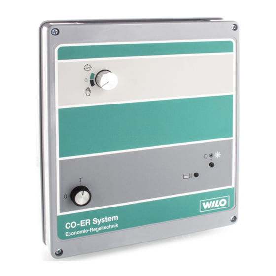
4.1 Frontseite des Schaltgerätes (Bild 1) – Hinweis für das Arbeiten mit schraubenlosen Klemmen: Bild 4 zeigt, Mit dem Schaltgerät ER 1 (-A) wird die Pumpe automatisch gesteuert. wie die Klemmen mit einem Schraubendreher zu öffnen sind. Eine Die Frontseite des Schaltgerätes enthält folgende Schalter bzw.
SSM: 6 Inbetriebnahme Bei jeder Störung und Überlaufwarnung. Vor Inbetriebnahme der Pumpenanlage mit dem Schaltgerät ER 1 (-A) Läßt sich die Betriebsstörung nicht beheben, wenden Sie sich sind die in Tabelle 2 aufgeführten Einstellungen für die verschiedenen bitte an Ihren Sanitär- und Heizungsfachhandwerker oder an Anwendungen auszuführen.
Ambient temperature: 0 – 40° C 4.3 Scope of supply Control unit ER 1 (-A) (ER 1-A: 2 float switches and a klaxon) 2 Safety Notes O. & M. Manual Safety reference and regulations as laid down in the Installation...
Chart II must have been set prior to initially starting-up of the connec- If the fault cannot be remedied please contact your Installer or ted pump plant. your nearest WILO service. Chart 1: Functions of hook switches and potentiometer (Fig. 2) Switch/Pot.
4.1 Platine avant du commutateur (Figure 1) 5.1 Montage Le commutateur ER 1 (-A) assure la gestion automatique de la pompe. L’appareil est fixé à la paroi au moyen de chevilles et de vis (Ø. = 4 mm). La platine avant de l’appareil présente les commutateurs et indicateurs Pour placer les chevilles, se servir du faux-châssis comme d’un gaba-...
être réglés pour répondre aux différentes fonctions Si les dysfonctionnements persistent, contacter votre spécia- de l’appareil. Cf. description dans le Tableau 1. liste sanitaire et chauffage ou le service clientèle de WILO. Tableau 1: Fonctions des crochets commutateurs et des potentiomètres (Figure 2) Commutateur/Potentiomètre...
Seite 14
FRANÇAIS Tableau 2: Réglages des crochets commutateurs et potentiomètres pour les diverses applications Commutateur/Potentiomètre Augmentation de la pression Installation d’extinction d’incendie Eaux-vannes** ver le haut ver le haut ver le bas 6P1 (R 10) conformément à la plaque signalétique du moteur 6P2 (R 27) 6P3 (R 48) ** 0...
4.1 Vooraanzicht van de schakelkast (afb. 1) – pomp/installatie volgens voorschrift aarden Met de schakelkast ER 1 (-A) wordt de pomp automatisch bestuurd. – netaansluitkabel voor DM-uitvoering: 4 x 1,5 mm , voor de EM-uit- Het kastfront bevat de onderstaande schakelaars/aanwijzingen: voering: 3 x 1,5 mm –...
WILO servicedienst. 6 Inbedrijfname Bij inbedrijfname van installaties met schakelkast ER 1 (-A) dienen de in tabel II aangegeven instellingen voor de diverse toepassingen uitge- voerd te worden. Tabel 1: functies van de haakschakelaar en potentiaalmeter (afb.
4.1 Panel de control del cuadro (fig. 1) 5.2 Conexión eléctrica (fig. 2) El sistema ER 1 (-A) regula la bomba de forma automática. La parte delantera del cuadro contiene los siguientes interruptores o indicacio- La instalación eléctrica la debe llevar a cabo un instalador nes: autorizado según las normas UNE vigentes.
Antes de proceder a la puesta en marcha de la bomba en combi- nación con el cuadro de regulación ER 1 (-A) debe llevar a cabo los Si no puede eliminar el fallo, diríjase al Distribuidor o Servicio ajustes para las diferentes aplicaciones descritos en la tabla II.
– Collegare la morsettiera come segue (figura 2): 4.1 Descrizione del prodotto e accessori (L), (N), PE: L’apparecchio ER 1 (-A) comanda è concepito per il comando auto- Rete elettrica 1~230 V, matico di una pompa. Sul frontale sono disposti i seguenti selettori e...
6 Messa in esercizio Per ogni blocco e segnalazione del pericolo di funzionamento a secco. Prima di procedere alla messa in esercizio dell’apparecchio ER 1 (-A), Se nonostante questi interventi gli inconvenienti persistono verificare ed eventualmente eseguire le impostazioni tenendo conto richiedere l’intervento dell’installatore oppure del Servizio...
4.1 A kapocsolókészülék homloklapja (1. ábra) – A hálózati bekötő kábel 3 fázisnál 4 x 1,5 mm , 1 fázisnál A ER 1 (-A) kapcsolókésülék a szivattyút automatikusan vezérli. A 3 x 1,5 mm készülék homloklapján a következő kapcsolók és jelzések –...
és fűtési kereskedőjéhez, vagy a WILO vevőszol- 6 Üzembehelyezés gálathoz. Mielőtt üzembe helyezzük az ER 1 (-A) kapcsolókészülékkel a szi- vattyútelepet, a 2. táblázatban leírt beállításikat el kell készíteni a különféle alkalmazásokhoz. 1. Táblázat: A potenciométerek és nyomógombos kapcsolók működése (2.
5.2 Połączenie elektryczne (rys. 2) Pompa sterowana jest automatycznie za pomocą urządzenia ste- Podłączenie elektryczne powinno byc wykonane zgod- rującego ER 1 (-A). Płyta czołowa urządzenia zawiera następujące nie z obowiązującymi przepisami VDE przez elektromon- przyłączniki i wskazania tera posiadającego uprawnienia wymagane przez miejs- –...
6 Uruchomienie SSM: połączenie dla zewnętrzn zbiorczej sygnalizacji awarii, bezpotenc- Przed uruchomieniem pompy z urządzeniem sterującym ER 1 (-A) jaŕowy styk przełączny, max. obciążenie styku 250 V, 1 A np. dla należy to urządzenie odpowiednio nastawić zgodnie z tabelą 2 dla podłączenia buczka.
4.1 Čelní stěna přístroje (obr. 1) – Návod pro práci se svorkami bez šroubů: Obr. 4 ukazuje, jak se Spínacím přístrojem ER 1 (-A) se čerpadlo ovládá automaticky. Na svorky otvírají přibaleným šroubovákem. Jedna svorka je pouze čelní stěně jsou tyto spínače a indikátory: pro jeden vodič.
Vypnuto pro nedostatek vody nebo přeplnění. Reset automaticky po odstranění příčiny poruchy. Před uvedením čerpacího agregátu se spínacím přístrojem ER 1 (-A) Resetovat lze i přepnutím ovládacího spínače do polohy ”0”. do provozu se pro různé aplikace musí provést nastavení, uvedená...
Seite 27
WA 65/95 ≤ º º º ER 1 (-A) ER 1-A: 2 WA 95, ER 1 (-A) L1, L 2, L 3 4 x 1,5 3 x 1,5 (L), (N), PE: L1, L2, L3, PE:...
Seite 28
L1, L2, L3, PE: ER 1 (-A) U, V, PE: U, V, W, PE: SBM: SSM: Option 24 V: Geber P: TLS: SSM: WSK: WILO.
Seite 32
EN 61439-2 EN 61000-6-1:2007 EN 61000-6-3+A1:2011 EN 61000-6-2:2005 EN 61000-6-4+A1:2011 Digital unterschrieben von Holger Herchenhein Dortmund, Datum: 2017.10.19 18:57:09 +02'00' H. HERCHENHEIN WILO SE Senior Vice President - Group ITQ Nortkirchenstra e 100 44263 Dortmund - Germany N°2117872.02 (CE-A-S n°2540433)
Seite 33
ES/EK ATBILST BAS DEKLAR CIJU DIKJARAZZJONI TA’ KONFORMITÀ UE/KE WILO SEdeklar , ka izstr d jumi, kas ir nosaukti šaj deklar cij , atbilst šeit WILO SE jiddikjara li l-prodotti spe ifikati f’din id-dikjarazzjoni huma konformi uzskait to Eiropas direkt vu nosac jumiem, k ar atseviš u valstu likumiem,...
Seite 34
WILO SE estne prehlasuje, že výrobky ktoré sú predmetom tejto deklarácie, sú v súlade s požiadavkami nasledujúcich európskych direktív a WILO SE izjavlja, da so izdelki, navedeni v tej izjavi, v skladu z dolo ili odpovedajúcich národných legislatívnych predpisov: naslednjih evropskih direktiv in z nacionalnimi zakonodajami, ki jih vsebujejo: Nízkonapä...
Seite 35
WILO Pompa Sistemleri Jakarta Timur, 13950 Sistemas Hidraulicos Lda. San. ve Tic. A.S¸ T +62 21 7247676 4475-330 Maia 34956 İstanbul citrawilo@cbn.net.id T +351 22 2080350 T +90 216 2509400 bombas@wilo.pt wilo@wilo.com.tr Further subsidiaries, representation and sales offices on www.wilo.com Oktober 2018...
Seite 36
WILO SE Nortkirchenstraße 100 D-44263 Dortmund Germany T +49(0)231 4102-0 F +49(0)231 4102-7363 wilo@wilo.com Pioneering for You www.wilo.com...