Siemens BOP-2 Commissioning
Basic operator panel
Vorschau ausblenden
Andere Handbücher für BOP-2:
- Betriebsanleitung (50 Seiten) ,
- Betriebsanleitung (58 Seiten)
Verfügbare Sprachen
Verfügbare Sprachen
Inhaltsverzeichnis
Basic Operator Panel - 2 (BOP-2)
*A5E02826349A*
The Basic Operator Panel 2 (BOP-2) has been designed to enhance the interface and
communications capabilities of SINAMICS Inverters.
The BOP-2 connects to the Inverter through an RS232 interface. It has been designed to
automatically recognise all variants of the following Control Units from the SINAMICS range:
SINAMICS G120 CU230P-2
SINAMICS G120 CU240B-2
SINAMICS G120 CU240E-2
Warnings
During commissioning of the Inverter it is essential to ensure that the system is in a
safe and stable state, as some commissioning processes have the potential to start
the motor. Therefore it is important to secure any loads and ensure that should the
motor start, no potentially dangerous conditions exist.
The BOP-2 can be fitted to and removed from the inverter while power is applied.
BOP-2, Getting Started Guide 03/10 A5E02826349A
Printed in the EU (United Kingdom)
1
Inhaltsverzeichnis

Verwandte Anleitungen für Siemens BOP-2


Inhaltszusammenfassung für Siemens BOP-2
- Seite 9 Basic Operator Panel - 2 (BOP-2) *A5E02826349A* Mit dem Basic Operator Panel 2 (BOP-2) werden die Schnittstellen- und Kommunikationsmöglichkeiten der SINAMICS-Umrichter optimiert. Das BOP-2 wird über eine RS-232-Schnittstelle an den Umrichter angeschlossen. Alle folgenden Control-Unit-Varianten der SINAMICS-Reihe werden automatisch erkannt: SINAMICS G120 CU230P-2 ...
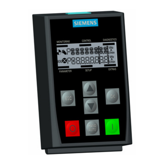
- Seite 10 Layout of BOP-2 Position Beschreibung Position Beschreibung ① Entriegelungseinrichtung ⑦ AUS-Taste ② LCD-Bildschirm ⑧ HAND/AUTO-Taste ③ ESC-Taste ⑨ EIN-Taste ④ AUF-Taste ⑩ Schraubvertiefung für Türmontage ⑤ AB-Taste ⑪ RS-232-Steckverbinder ⑥ OK-Taste ⑫ Typenschild BOP-2, Getting Started Guide 03/10 A5E02826349A...
- Seite 11 Beim Ändern eines Parameterwerts wird der angezeigte Wert durch Drücken der Taste verringert. Die ESC-Taste hat folgende Funktionen: Wird die Taste kürzer als 2 Sekunden gedrückt, kehrt das BOP-2 zum vorherigen Bildschirm zurück oder, falls ein Wert geändert wurde, wird der neue Wert nicht gespeichert. ...
- Seite 12 3 Sekunden lang gedrückt, um das Tastenfeld zu entriegeln. Bildschirmsymbole Auf der linken Seite der Anzeige des BOP-2 stellen einige Symbole den tatsächlichen Zustand des Umrichters dar. Diese Symbole sind in nachstehender Tabelle erläutert. Tabelle Error! No text of specified style in document.- 1Beschreibung der Bildschirmsymbole...
- Seite 13 0. 0 0 MOT RPM 400. 0 10. 0 400. 0 MOT ID 1500. 0 1900 CMD SRC MAIN SP 1000 ADD SP 1000 MIN RPM 1080 RAMP UP 1120 RAMP DWN 1121 FINISH 3900 BOP-2, Getting Started Guide 03/10 A5E02826349A...
- Seite 14 Setzen Sie die Unterkante des BOP-2-Gehäuses in die untere Vertiefung des Control-Unit- Gehäuses. Schieben Sie das BOP-2 in Richtung Control Unit bis die Entriegelungseinrichtung auf dem Control-Unit-Gehäuse richtig einrastet. Drücken Sie zum Entfernen des BOP-2 von der Control Unit die Entriegelungseinrichtung nach unten und ziehen Sie das BOP-2 von der Control Unit ab.
-
Seite 15: Erstes Einschalten
Erstes Einschalten Nachdem das BOP-2 eingebaut und eingeschaltet wurde, erkennt es automatisch, an welchem Control-Unit-Typ es angebracht wurde und versucht, eine Kommunikationsverbindung automatisch aufzubauen. Sobald die Kommunikationsverbindung aufgebaut ist, wird eine MONITORING MONITORING CONTROL CONTROL DIAGNOSTICS DIAGNOSTICS CU RESP interne Prüfung durchgeführt, die eine korrekte Reaktion des Bediengeräts sicherstellt. - Seite 16 Ziffern wird dieser Eingabemodus verlassen. Sowohl durch Verschieben wie auch durch das Ändern der einzelnen Ziffern können alle angezeigten Werte verändert werden, z. B. Parameter, Indizes und Einstellungswerte. PARAMETER PARAMETER SETUP SETUP EXTRAS EXTRAS BOP-2, Getting Started Guide 03/10 A5E02826349A...