Herunterladen Inhalt Inhalt Diese Seite drucken
Inhaltsverzeichnis

Werbung

Verfügbare Sprachen
  • DE

Verfügbare Sprachen

  • DEUTSCH, seite 4
FDV241
Video Fire Controller
Inbetriebnahmeanleitung (DE)
Startup Manual (EN)
Manual de inicio (ES)
Manuel de mise en service (FR)
Manuale di messa in servizio (IT)
SISTORE V3.5
Building Technologies
Fire Safety and Security Products

Werbung

Inhaltsverzeichnis
loading

Inhaltszusammenfassung für Siemens FDV241

  • Seite 1 FDV241 Video Fire Controller Inbetriebnahmeanleitung (DE) Startup Manual (EN) Manual de inicio (ES) Manuel de mise en service (FR) Manuale di messa in servizio (IT) SISTORE V3.5 Building Technologies Fire Safety and Security Products...
  • Seite 2 Data and design subject to change without notice. / Supply subject to availability. © 2008 Copyright by Siemens Building Technologies We reserve all rights in this document and in the subject thereof. By acceptance of the document the recipient acknowledges these rights and undertakes not to publish the document nor the subject thereof in full or in part, nor to make them available to any third party without our prior express written authorization, nor to use it for any purpose other than for which it was delivered to him.
  • Seite 3 FDV241 Video Fire Controller Inbetriebnahmeanleitung SISTORE V3.5 Building Technologies Fire Safety and Security Products...
  • Seite 4 Liefermöglichkeiten und technische Änderungen vorbehalten. © 2008 Copyright by Siemens Building Technologies Wir behalten uns alle Rechte an diesem Dokument und an dem in ihm dargestellten Gegenstand vor. Der Empfänger erkennt diese Rechte an und wird dieses Dokument nicht ohne unsere vorgängige schriftliche Ermächtigung ganz oder teilweise Dritten zugänglich machen oder...
  • Seite 5: Inhaltsverzeichnis

    Transponder FDCC221 (in FDV241 enthalten)........11 Bestellangaben ..................12 Lieferumfang..................12 Gerätebeschreibung................13 Anzeigen ....................13 Anschlüsse ....................14 FDnet spezifische Aspekte ..............16 7.3.1 Beispiel zur Anwendung des Video Fire Controllers FDV241 ....16 7.3.2 Diagnosestufen im FDnet ..............17 7.3.3 Notlauf im FDnet ...................17 Wandmontage..................18 Inbetriebnahme..................19 Gerät öffnen oder schließen ..............19 Gerät hoch- oder herunterfahren ............20...
  • Seite 7: Zu Diesem Dokument

    Zwecke der Identifikation oder der Beschreibung und können Warenzeichen oder eingetragene Warenzeichen der jeweiligen Eigentümer sein. SISTORE ist ein Warenzeichen der Siemens Building Technologies Fire & Security Products GmbH & Co. oHG. Microsoft ist ein eingetragenes Warenzeichen und Windows ist ein Warenzeichen der Microsoft Corporation.
  • Seite 8: Sicherheit

    Sicherheit Sicherheit Zielgruppe Die Anweisungen in diesem Dokument richten sich nur an die folgenden Zielgruppen: Zielgruppe Tätigkeit Qualifikation Produkt Manager (PM) Betreibt lokales Produktmanagement und ist Besitzt eine zur Funktion und zum verantwortlich für den Informationsaustausch zwischen Produktsortiment passende Fachausbildung dem Lieferwerk und seiner DU für sein und hat die Ausbildungskurse für den PM Produktsortiment.
  • Seite 9: Transport

    Sicherheit Haftungsanspruch Schließen Sie das Gerät nur an, wenn es unbeschädigt ist und wenn der Lieferumfang vollständig ist. Nehmen Sie nur Veränderungen am Gerät vor, die in diesem Dokument erwähnt sind oder vom Hersteller genehmigt wurden. Verwenden Sie nur vom Hersteller genehmigte Ersatz- und Zubehörteile. Arbeiten an elektrischen Anlagen dürfen nur von einer geschulten Elektrofachkraft oder unterwiesenen Personen unter Leitung und Aufsicht einer Elektrofachkraft den elektrotechnischen Regeln entsprechend vorgenommen...
  • Seite 10: Installation

    Sicherheit Geräteschaden durch überhöhte Spannung Schließen Sie das Gerät nur an Stromquellen mit der angegebenen Spannung an. Auf dem Typenschild finden Sie Hinweise zur Spannungsversorgung. 2.2.4 Installation Datenverlust bei Aktualisierung der Software Sichern Sie alle Daten bevor Sie die Software auf dem Gerät aktualisieren. Bedeutung von Signalwörtern Auf die Schwere der Gefahr wird mit Signalworten hingewiesen.
  • Seite 11: Richtlinien Und Normen

    Die EG-Richtlinie 2004/108/EC „Elektromagnetische Verträglichkeit” wird nur mit einem Ferritkern erfüllt (siehe Kap. 9.6: Ferritkern anbringen). Das Produkt erfüllt die Anforderungen der nachfolgenden EG-Richtlinien. Die EG-Konformitätserklärung wird zur Verfügung gestellt bei: Siemens Building Technologies Fire & Security Products GmbH & Co. oHG 76181 Karlsruhe Deutschland EG-Richtlinie 2004/108/EC „Elektromagnetische Verträglichkeit”...
  • Seite 12: Technische Daten

    Technische Daten Technische Daten Video Fire Controller FDV241 Anwendung Codieren und decodieren von Videosignalen, Videoübertragung, Videoaufzeichnung und Videoauswertung Betriebstemperatur -10 bis +50 °C Relative Luftfeuchtigkeit 20 – 80 % ohne Kondensation Gewicht 0,95 kg Spannungsversorgung 12 – 24 V DC oder 24 V AC, max. 1,25 A Die Spannungsversorgung für das Gerät muss den Spezifikationen SELV (Safety...
  • Seite 13 Technische Daten Transponderanschluss FDCC221 (in FDV241 enthalten) Anschlüsse Ausführung: Steckeranschlüsse Querschnitt: 0,2 – 1,5 mm Betriebsspannung 12 – 33 V DC Betriebsstrom (Ruhe) 0,6 – 0,75 mA Betriebstemperatur -10 bis +55 °C Relative Luftfeuchtigkeit ≥ 95 % rel. (bei T = 25 ±3°C) 93 % rel.
  • Seite 14: Bestellangaben

    Bestellangaben Bestellangaben Art-Nr. Bezeichnung Gewicht FDV241 S54335-F1-A1 Video Fire Controller 0,95 kg Zubehör, nicht im Lieferumfang enthalten! Empfohlenes Zubehör Art-Nr. Bezeichnung Gewicht CCBC1345-LP 2GF1183-8GA 1/3" DSP Colour DIP Switch Camera 480 TVL, 0,45 kg PAL, 12 V DC / 24 V AC CLVD1314/3.5-8...
  • Seite 15: Gerätebeschreibung

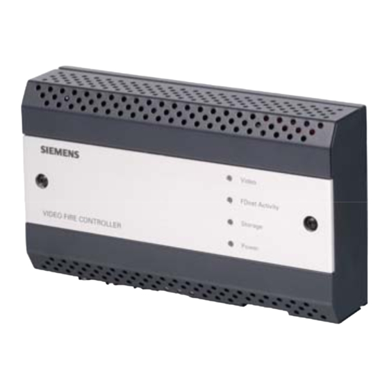
    Gerätebeschreibung Gerätebeschreibung Anzeigen Anzeigen an der Vorderseite Abb. 1 Anzeigen Video Fire Controller Video Anzeige aus: Keine Kamera angeschlossen Rot: Alarm, Initialisierung, Überhitzung Grün: Kamerasignal liegt an Orange: Livebild oder Aufnahme Rot, grün oder Gerät startet oder fährt herunter orange blinkend: FDnet Activity Anzeige aus: Keine oder fehlerhafte FDnet Anbindung...
  • Seite 16: Anschlüsse

    Gerätebeschreibung Anschlüsse Abb. 2 Anschlüsse Video Fire Controller 1 Videoeingang Anschluss von 75 Ohm-BNC-Kabel 1 Videoausgang Anschluss von 75 Ohm-BNC-Kabel 1 Videoschleife Anschluss von 75 Ohm-BNC-Kabel 1 Abschlusswiderstand On: Videosignal nicht durchschleifen Off: Videosignal zu anderem Videoeingang durchschleifen USB 2.0 max.
  • Seite 17 Gerätebeschreibung Pinbelegung Anschlussblock 7 Audio Eingang (-) Digitaler Ausgang #2 (+) Audio Eingang (+) Digitaler Ausgang #2 (-) Audio Ausgang (-) Digitaler Eingang #1 (+) Audio Ausgang (+) Digitaler Eingang #1 (-) Nicht unterstützt Digitaler Eingang #2 (+) Nicht unterstützt Digitaler Eingang #2 (-) Digitaler Ausgang #1 (+) RS485 (D+)
  • Seite 18: Fdnet Spezifische Aspekte

    Im Fall einer Störung am Video Fire Controller, wird eine Störung zur Brandmeldezentrale übermittelt. Vergleichen Sie hierzu Kap. 13: Störungsabhilfe. 7.3.1 Beispiel zur Anwendung des Video Fire Controllers FDV241 F C 20 x x F C 20 x x F ire...
  • Seite 19: Diagnosestufen Im Fdnet

    Peripheriegerät zugeordnet ist. Die aufgenommenen Bilder werden dann mit einer vordefinierten Vor- und Nachlaufzeit auf dem Compact Flash gespeichert. Sie können den Video Fire Controller zusätzlich an ein CCTV-System anschließen. Vergleichen Sie hierzu Kap. 9.5: Video Fire Controller FDV241 an FDnet und CCTV-System anschließen. 7.3.2 Diagnosestufen im FDnet Der Video Fire Controller überwacht seine Funktion weitgehend selbst.
  • Seite 20: Wandmontage

    Wandmontage Wandmontage Überhitzung des Gerätes Bei Überhitzung wird das Gerät automatisch heruntergefahren. Die LED 1 an der Vorderseite des Gerätes leuchtet rot. Prüfen Sie den Mindestabstand von 10 cm zu den Belüftungslöchern am WICHTIG Gehäusedeckel. Prüfen Sie die Umgebungstemperatur. Vergleichen Sie hierzu Kap.
  • Seite 21: Inbetriebnahme

    Inbetriebnahme Inbetriebnahme Gerät öffnen oder schließen Abb. 4 Video Fire Controller – Schrauben an der Gerätevorderseite Gerät öffnen Lösen Sie die Schrauben an der Gerätevorderseite. Ziehen Sie den Gehäusedeckel vom Gerät. Gerät schließen Beschädigung des Gerätes Gefahr einer Beschädigung beim Schließen des Gerätes. WICHTIG Achten Sie beim Schließen des Gerätes darauf, dass die Lichtleiter im Gehäusedeckel bzw.
  • Seite 22: Gerät Hoch- Oder Herunterfahren

    Inbetriebnahme Gerät hoch- oder herunterfahren Abb. 5 Video Fire Controller – ON/OFF Schalter Öffnen Sie das Gerät. Vergleichen Sie hierzu Kap. 9.1: Gerät öffnen oder schließen. Halten Sie zum Herunterfahren des Gerätes den ON/OFF Schalter (1) ca. zwei Sekunden gedrückt. Das Gerät fährt herunter, dies kann einige Sekunden dauern.
  • Seite 23: Compact Flash Karte Ein- Und Ausbauen

    Inbetriebnahme Compact Flash Karte ein- und ausbauen Die Compact Flash Karte ermöglicht eine lokale Videoaufzeichnung. Die Aufzeichnungsdauer hängt vom Video-Stream und der Speicherkapazität ab. Beispiel Bei einer Speicherkapazität der Compact Flash Karte von 4 GB, einem Bildformat von 4CIF bei Standard Qualität und einer Übertragungsgeschwindigkeit von 1 MB/s kann der Video-Stream ca.
  • Seite 24 Inbetriebnahme Compact Flash Karte einbauen Wählen Sie einen der empfohlenen Compact Flash. Öffnen Sie das Gerät. Vergleichen Sie hierzu Kap. 9.1: Gerät öffnen oder schließen. Halten Sie den ON/OFF Schalter (1) ca. zwei Sekunden gedrückt. Das Gerät fährt herunter, dies kann einige Sekunden dauern. Die Power LED (3) leuchtet nicht mehr, wenn das Gerät heruntergefahren ist.
  • Seite 25: Video Fire Controller Fdv241 An Fdnet Anschließen (Ohne Cctv-Anbindung)

    Inbetriebnahme Video Fire Controller FDV241 an FDnet anschließen (ohne CCTV-Anbindung) Brandmelder FDV241 FDnet Brandmeldezentrale Handfeuermelder 1 Kamera Abb. 7 Video Fire Controller an FDnet ohne CCTV-Anbindung Abb. 8 Anschlüsse Video Fire Controller Betreiben Sie das Gerät an der Hutschiene. Vergleichen Sie hierzu Kap.
  • Seite 26 12. Schließen Sie den Video Fire Controller an das FDnet (9) an. 13. Konfigurieren Sie das Gerät an der Brandmeldezentrale. Vergleichen Sie hierzu Kap. 12: FDV241 an der Brandmeldezentrale konfigurieren. Weitere Informationen zur Konfiguration und Inbetriebnahme der Brandmeldezentrale finden Sie im Konfigurations- und Benutzerhandbuch der Brandmeldezentrale.
  • Seite 27: Video Fire Controller Fdv241 An Fdnet Und Cctv-System Anschließen

    Inbetriebnahme Video Fire Controller FDV241 an FDnet und CCTV-System anschließen Sie können den Video Fire Controller an ein CCTV-System anschließen. Dadurch werden dieselben CCTV-Funktionen unterstützt, die SISTORE CX1 bietet. Die Verbindung zum CCTV-System wird via Ethernet hergestellt. Der Video Fire Controller kann wie alle CCTV-Geräte über IVM bedient werden.
  • Seite 28: Anlagenbetrieb Mit Mehreren Geräten

    11. Schließen Sie den Video Fire Controller an das FDnet an (9). 12. Konfigurieren Sie das Gerät an der Brandmeldezentrale. Vergleichen Sie hierzu Kap. 12: FDV241 an der Brandmeldezentrale konfigurieren. Weitere Informationen zur Konfiguration und Inbetriebnahme der Brandmeldezentrale finden Sie im Konfigurations- und Benutzerhandbuch der Brandmeldezentrale.
  • Seite 29 13. Schließen Sie die Video Fire Controller an das FDnet an (9). 14. Konfigurieren Sie die Geräte an der Brandmeldezentrale. Vergleichen Sie hierzu Kap. 12: FDV241 an der Brandmeldezentrale konfigurieren. Weitere Informationen zur Konfiguration und Inbetriebnahme der Brandmeldezentrale finden Sie im Konfigurations- und Benutzerhandbuch der Brandmeldezentrale.
  • Seite 30: Ferritkern Anbringen

    Inbetriebnahme Ferritkern anbringen Die EG-Richtlinie 2004/108/EC „Elektromagnetische Verträglichkeit” wird nur mit einem Ferritkern erfüllt. Der Klappferritkern Typ 74271132 der Firma Würth ist im Lieferumfang enthalten. Der Abstand zwischen Ferritkern und Gerät darf max. 100 mm betragen. Falls das verwendete I/O Kabel nicht in den mitgelieferten Klappferritkern WICHTIG passt, verwenden Sie einen anderen Ferritkern mit den entsprechenden elektrischen Eigenschaften.
  • Seite 31: Ip-Adresse Des Client-Pcs Einstellen

    Inbetriebnahme IP-Adresse des Client-PCs einstellen Klicken Sie im Windows Start Menü auf Start > Einstellungen > Systemsteuerung > Netzwerkverbindungen. Klicken Sie mit der rechten Maustaste auf die ausgewählte Netzwerkverbindung. Wählen Sie aus dem Kontextmenü den Menüpunkt Eigenschaften. Das Dialogfenster Eigenschaften von Local Area Connection öffnet sich. Wählen Sie ein Internetprotokoll (TCP/IP) aus.
  • Seite 32: Software

    Software Software 10.1 Systemvoraussetzungen für den Client-PC Für den Betrieb der SISTORE Client Software auf den Client-PC empfehlen wir Ihnen: Intel Pentium 4; mind. 2 GHz Prozessor – oder – AMD Athlon 2800 +; mind. 2 GHz – oder – höher 512 MB Arbeitsspeicher...
  • Seite 33: Konfiguration

    Hilfe der Konfigurationsdatei vfc.xml. Weitere Informationen hierzu finden Sie im SISTORE SX/CX Konfigurationshandbuch. 11.1 Software SISTORE SX/CX Config aufrufen Wählen Sie im Windows Start Menü Start > Programme > SIEMENS Video Software Suite > SISTORE SX-CX Config. Abb. 14 SISTORE SX/CX Startmenü...
  • Seite 34: Fdv241 An Der Brandmeldezentrale Konfigurieren

    FDV241 an der Brandmeldezentrale konfigurieren FDV241 an der Brandmeldezentrale konfigurieren Weitere Informationen zur Konfiguration und Inbetriebnahme der Brandmeldezentrale finden Sie im Konfigurations- und Benutzerhandbuch der Brandmeldezentrale. Folgende Einstellungen sind im Video Fire Controller hinterlegt und müssen auf der Brandmeldezentrale konfiguriert werden: Beachten Sie die Kompatibilität.
  • Seite 35: Störungsabhilfe

    Störungsabhilfe Störungsabhilfe Bei einer Störung, die die Funktion des Video Fire Controllers FDV241 beeinträchtigt, erscheint eine Meldung an der Brandmeldezentrale. Zur Behebung der Ursache sind zusätzliche Informationen im Video Fire Controller verfügbar. Diese können beispielsweise durch den Prüfpflücker FDUD29x angezeigt werden (Details siehe Bedienungsanleitungen Prüfpflücker, Dok.-Nr.
  • Seite 36 Siemens Schweiz AG Building Technologies Group International Headquarters Fire Safety & Security Products Gubelstrasse 22 © 2008 Copyright by CH-6301 Zug Siemens Schweiz AG Tel. +41 41 724 24 24 Liefermöglichkeiten und technische Änderungen vorbehalten. Fax +41 41 724 35 22 www.sbt.siemens.com...
  • Seite 37 FDV241 Video Fire Controller Startup Manual SISTORE V3.5 Building Technologies Fire Safety and Security Products...
  • Seite 38 Data and design subject to change without notice. / Supply subject to availability. © 2008 Copyright by Siemens Building Technologies We reserve all rights in this document and in the subject thereof. By acceptance of the document the recipient acknowledges these rights and undertakes not to publish the document nor the subject thereof in full or in part, nor to make them available to any third party without our prior express written authorization, nor to use it for any purpose other than for which it was delivered to him.
  • Seite 39 Scope of delivery.................12 Description of the device ..............13 LEDs .....................13 Connections ..................14 FDnet-specific aspects ................16 7.3.1 Example for the use of the Video Fire Controller FDV241 .....16 7.3.2 Diagnosis levels in FDnet ..............17 7.3.3 Degraded mode in FDnet ..............17 Wall mounting..................18 Setup ....................19...
  • Seite 41: About This Document

    SISTORE is a trademark of Siemens Building Technologies Fire & Security Products GmbH & Co. oHG. Microsoft is a registered trademark and Windows a trademark of Microsoft Corporation.
  • Seite 42: Safety

    Safety Safety Target group The instructions in this document are designed only for the following target readers: Target readers Activity Qualification Product Manager (PM) Local product management; responsible for the Has appropriate professional training with information exchange between the plant supplying the regard to his function and the range of equipment and his DU for his product line.
  • Seite 43: Transport

    Safety Liability claim Do not connect the device if it is damaged or any parts are missing. Do not make any changes or modifications to the device unless they are expressly mentioned in this manual and have been approved by the manufacturer.
  • Seite 44: Meaning Of The Written Warning Notices

    Safety Damage to the device due to overvoltage Connect the device only to power sources with the specified voltage. Voltage supply requirements can be found on the type label. 2.2.4 Installation Data loss after software update Make sure to backup all data before updating the software. Meaning of the written warning notices The severity of a hazard is indicated by the following written warning notices.
  • Seite 45: Directives And Standards

    (see Section 9.6: Installing the ferrite core). This product complies with the requirements of the following European directives. The EU declaration of conformity is available from: Siemens Building Technologies Fire & Security Products GmbH & Co. oHG 76181 Karlsruhe Germany European Directive 2004/108/EC „Electromagnetic Compatibility”...
  • Seite 46: Technical Data

    Technical data Technical data Video Fire Controller FDV241 Application Encoding and decoding of video signals, transmission, recording and evaluation Operating temperature -10 to +50 °C Relative humidity 20 – 80 % without condensation Weight 0.95 kg Power supply 12 – 24 V DC or 24 V AC, max. 1.25 A...
  • Seite 47: Transponder Fdcc221 (Integrated In Fdv241)

    Technical data Connection to transponder FDCC221 (integrated in FDV241) Connections Design: plug-type connection Cross-section: 0.2 – 1.5 mm Operating voltage 12 – 33 V DC Operating current (closed circuit) 0.6 – 0.75 mA Operating temperature -10 to +55 °C, Relative humidity ≥...
  • Seite 48: Details For Ordering

    Details for ordering Details for ordering Type Order no. Designation Weight FDV241 S54335-F1-A1 Video Fire Controller 0.95 kg Accessories, not included in the delivery! Recommended accessories Type Order no. Designation Weight CCBC1345-LP 2GF1183-8GA 1/3" DSP colour DIP switch camera 480 TVL, PAL, 0.45 kg...
  • Seite 49: Description Of The Device

    Description of the device Description of the device LEDs Displays on the front side Fig. 1 Displays on the Video Fire Controller Video No indicator: No camera connected Red: Alarm, initializing, overheated Green: Receiving camera signal Orange: Live image or recording Blinking red, Device starting up or shutting down green or orange:...
  • Seite 50: Connections

    Description of the device Connections Fig. 2 Connections on the Video Fire Controller 1 video input Connection for 75 Ω BNC cable 1 video output Connection for 75 Ω BNC cable 1 video loop Connection for 75 Ω BNC cable 1 terminating resistor On: no video signal loop-through Off: video signal loops through to another video input...
  • Seite 51 Description of the device Pin assignment terminal block 7 Audio input (-) Digital output #2 (+) Audio input (+) Digital output #2 (-) Audio output (-) Digital input #1 (+) Audio output (+) Digital input #1 (-) Not supported Digital input #2 (+) Not supported Digital input #2 (-) Digital output #1 (+)
  • Seite 52: Fdnet-Specific Aspects

    The Video Fire Controller is connected to a camera and to the FDnet. See Section 9.4: Connecting the Video Fire Controller FDV241 to the FDnet. When an alarm is triggered via a peripheral device (e.g. manual call point), a message is sent to the Building Technologies Fire Safety &...
  • Seite 53: Diagnosis Levels In Fdnet

    The images captured by the camera are then stored on the compact flash with a predefined pre-event and post-event recording time. The Video Fire Controller can be additionally connected to a CCTV system. See Section 9.5: Connecting the Video Fire Controller FDV241 to the FDnet and to the CCTV system. 7.3.2 Diagnosis levels in FDnet The Video Fire Controller is largely self-monitoring.
  • Seite 54: Wall Mounting

    Wall mounting Wall mounting Overheating of the device In case of overheating the device will shut down automatically. LED 1 on the front of the device will be lit red. IMPORTANT Check to ensure there is a minimum clearance of 10 cm to the ventilation holes on the housing cover.
  • Seite 55: Setup

    Setup Setup Opening/closing the device Fig. 4 Video Fire Controller – Screws on the front side of the device Opening the device Remove the screws on the front side of the device. Remove the housing cover. Closing the device Damage to the device Risk of damage when closing the device.
  • Seite 56: Switching The Device On Or Off

    Setup Switching the device on or off Fig. 5 Video Fire Controller – ON/OFF switch Open the device. See Section 9.1: Opening/closing the device. To shut down the device, press the ON/OFF switch (1) for approx. 2 seconds. The device switches off, which can take several seconds. Once the device is switched off, the Power LED (2) will no longer be lit.
  • Seite 57: Inserting And Removing The Compact Flash Card

    Setup Inserting and removing the compact flash card The compact flash card enables local video recording. The length of the recording depends on the video stream and on the storage capacity. Example If the compact flash card has a storage capacity of 4 GB, an image format of 4CIF at standard quality and a transfer rate of 1 MB/s, then the video stream can be recorded for approx.
  • Seite 58 Setup Inserting the compact flash card Select a recommended compact flash. Open the device. See Section 9.1: Opening/closing the device. Press and hold the ON/OFF switch (1) for approx. 2 seconds. The device switches off, which can take several seconds. Once the device is switched off, the Power LED (3) will no longer be lit.
  • Seite 59: Connecting The Video Fire Controller Fdv241 To The Fdnet (Without Connection To The Cctv System)

    Setup Connecting the Video Fire Controller FDV241 to the FDnet (without connection to the CCTV system) Fire detectors FDV241 FDnet Fire panel Manual call point 1 camera Fig. 7 Video Fire Controller connected to the FDnet, without connection to the CCTV system Fig.
  • Seite 60 Setup 13. Configure the device on the fire control panel. See Section 12: Configuring FDV241 on the fire control panel. More detailed information on the configuration and setup of the fire control panel can be found in the configuration and user manual for the fire control panel.
  • Seite 61: Connecting The Video Fire Controller Fdv241 To The Fdnet And To The Cctv System

    Setup Connecting the Video Fire Controller FDV241 to the FDnet and to the CCTV system The Video Fire Controller can be connected to a CCTV system. It then supports the same CCTV functions as SISTORE CX1. The connection to the CCTV system is set up via Ethernet.
  • Seite 62: Multiple-Device System

    11. Connect the Video Fire Controller to the FDnet (9). 12. Configure the device on the fire control panel. See Section 12: Configuring FDV241 on the fire control panel. More detailed information on the configuration and setup of the fire control panel can be found in the configuration and user manual for the fire control panel.
  • Seite 63 13. Connect the Video Fire Controllers to the FDnet (9). 14. Configure the devices on the fire control panel. See Section 12: Configuring FDV241 on the fire control panel. More detailed information on the configuration and setup of the fire control panel can be found in the configuration and user manual for the fire control panel.
  • Seite 64: Installing The Ferrite Core

    Setup Installing the ferrite core Compliance with the European Directive 2004/108/EC „Electromagnetic Compatibility” will be achieved only if the device is equipped with a a ferrite core. The snap-on ferrite core type 74271132 (manufacturer: Würth) is included in the delivery. The distance between the ferrite core and the device must not exceed 100 IMPORTANT In case the I/O cable used should not fit into the snap-on ferrite core supplied,...
  • Seite 65: Setting The Ip Address Of The Client Pc

    Setup Setting the IP address of the client PC Select Start > Settings > Control Panel > Network Connections in the Windows Start menu. Right-click on the selected network connection. Select Properties in the context menu. The Local Area Connection Properties dialog box appears. Select an Internet protocol (TCP/IP).
  • Seite 66: Software

    Software Software 10.1 System requirements for the client PC The PC on which the SISTORE Client Software is installed should meet the following requirements: Intel Pentium 4; 2 GHz or faster Processor – OR – AMD Athlon 2800+; 2 GHz or faster –...
  • Seite 67: Configuration

    Further information on this can be found in the SISTORE SX/CX configuration manual. 11.1 Starting the SISTORE SX/CX Config software Select Start > Programs > SIEMENS Video Software Suite > SISTORE SX- CX Config in the Windows start menu. Fig. 14 SISTORE SX/CX start menu –...
  • Seite 68: Configuring Fdv241 On The Fire Control Panel

    Configuring FDV241 on the fire control panel Configuring FDV241 on the fire control panel More detailed information on the configuration and setup of the fire control panel can be found in the configuration and user manual for the fire control panel.
  • Seite 69: Trouble Shooting

    Trouble shooting When an error occurs which affects the proper function of the Video Fire Controllers FDV241, a message is generated on the fire control panel. To remedy the cause, additional information is available in the Video Fire Controller. This...
  • Seite 70 Siemens Schweiz AG Building Technologies Group International Headquarters Fire Safety & Security Products © 2008 Copyright by Gubelstrasse 22 Siemens Schweiz AG CH-6301 Zug Data and design subject to change without notice. Tel. +41 41 724 24 24 Supply subject to availability.
  • Seite 71 FDV241 Video Fire Controller Manual de inicio SISTORE V3.5 Building Technologies Fire Safety and Security Products...
  • Seite 72 Datos y diseño sujetos a modificaciones sin previo aviso. / Suministro sujeto a disponibilidad. © 2008 Copyright de Siemens Building Technologies El fabricante se reserva todos los derechos sobre este documento y el asunto en él tratado. Al aceptar este documento, el receptor reconoce estos derechos y se compromete a no publicar el documento ni el asunto en él tratado ya sea total o parcialmente, y a no ponerlo...
  • Seite 73 Inserción y extracción de la tarjeta Compact Flash .......21 Conexión del Video Fire Controller FDV241 a FDnet (sin conexión al sistema CCTV) ..............23 Conexión del Video Fire Controller FDV241 a FDnet y al sistema CCTV ..................25 9.5.1 Sistema de dispositivo único ..............25 9.5.2...
  • Seite 75: Acerca De Este Documento

    SISTORE es una marca comercial de Siemens Building Technologies Fire & Security Products GmbH & Co. oHG. Microsoft es una marca comercial registrada y Windows es una marca comercial de Microsoft Corporation.
  • Seite 76: Seguridad

    Seguridad Seguridad Grupo objetivo Las instrucciones de este documento están destinadas sólo a los siguientes lectores: Grupo objetivo Actividad Cualificación Product Manager (PM) Gestión de producto local; responsable del intercambio Ha recibido formación profesional para esta de información entre la planta que suministra el equipo función y para la gama de productos, y ha y su unidad de desarrollo para esta línea de producto.
  • Seite 77: Transporte

    Seguridad Declaración de responsabilidad No conecte el dispositivo si está dañado o faltan piezas. No realice cambios ni modificaciones en el dispositivo a no ser que se mencionen expresamente en este manual y los haya aprobado el fabricante. Utilice sólo piezas de recambio y accesorios aprobados por el fabricante. El trabajo con sistemas eléctricos debería ser realizado únicamente por personal formado bajo la supervisión de un técnico en electricidad certificado y según las normas correspondientes.
  • Seite 78: Instalación

    Seguridad Daños en el dispositivo por sobretensión Conecte el dispositivo sólo a fuentes de corriente con el voltaje especificado. En la etiqueta de tipo pueden leerse los requisitos de suministro de voltaje. 2.2.4 Instalación Pérdida de datos tras la actualización del software Asegúrese de realizar copias de seguridad de todos los datos antes de actualizar el software.
  • Seite 79: Directivas Y Normas

    9.6: Instalación del núcleo de ferrita). Este producto cumple los requisitos de las siguientes directivas europeas: La declaración de la UE de conformidad se encuentra disponible en: Siemens Building Technologies Fire & Security Products GmbH & Co. oHG 76181 Karlsruhe Alemania Directiva europea 2004/108/EC "Compatibilidad electromagnética"...
  • Seite 80: Datos Técnicos

    Datos técnicos Datos técnicos Video Fire Controller FDV241 Aplicación Codificación y descodificación de señales de vídeo, transmisión, grabación y evaluación Temperatura de de -10 a +50 °C funcionamiento Humedad relativa 20 – 80 % sin condensación Peso 0,95 kg Fuente de alimentación 12 –...
  • Seite 81: Conexión A Transpondedor Fdcc221 (Integrado En Fdv241)

    Datos técnicos Conexión a transpondedor FDCC221 (integrado en FDV241) Conexiones Diseño: conexión tipo clavija Sección transversal: 0,2 – 1,5 mm Voltaje de funcionamiento 12 – 33 V CC Corriente de funcionamiento 0,6 – 0,75 mA (circuito cerrado) Temperatura de de -10 a +55 °C...
  • Seite 82: Referencias De Pedido

    Referencias de pedido Referencias de pedido Tipo Nº de pedido Nombre Peso FDV241 S54335-F1-A1 Video Fire Controller 0,95 kg Los accesorios no se incluyen en la entrega Accesorios recomendados Tipo Nº de pedido Nombre Peso CCBC1345-LP 2GF1183-8GA Cámara DSP color de 1/3" con interruptor DIP...
  • Seite 83: Descripción Del Dispositivo

    Descripción del dispositivo Descripción del dispositivo Indicadores en la parte delantera Fig. 1 Indicadores en el Video Fire Controller Vídeo Sin indicador: Ninguna cámara conectada Rojo: Alarma, iniciando, sobrecalentamiento Verde: Recibiendo señal de la cámara Naranja: Imagen o grabación en directo Parpadea en rojo, Dispositivo iniciándose o apagándose verde o naranja:...
  • Seite 84: Conexiones

    Descripción del dispositivo Conexiones Fig. 2 Conexiones en el Video Fire Controller 1 entrada de vídeo Conexión para cable BNC de 75 Ω 1 salida de vídeo Conexión para cable BNC de 75 Ω 1 interconexión de vídeo Conexión para cable BNC de 75 Ω 1 resistor de terminación Act.: no hay interconexión de señal de vídeo Desact.: hay interconexión de la señal de vídeo a otra entrada...
  • Seite 85 Descripción del dispositivo Asignación de contactos bloque terminal 7 Entrada de audio (-) Salida digital nº 2 (+) Entrada de audio (+) Salida digital nº 2 (-) Salida de audio (-) Entrada digital nº 1 (+) Salida de audio (+) Entrada digital nº...
  • Seite 86: Aspectos Específicos De Fdnet

    Fig. 3 Ejemplo de uso El Video Fire Controller está conectado a una cámara y a FDnet. Consulte la sección 9.4: Conexión del Video Fire Controller FDV241 a FDnet. Cuando se Building Technologies Fire Safety & Security Products 11.2008...
  • Seite 87: Niveles De Diagnóstico En Fdnet

    Las imágenes captadas por la cámara se almacenan en la tarjeta Compact Flash junto con las secuencias anteriores y posteriores a evento predefinidas. El Video Fire Controller se puede conectar también a un sistema CCTV. Consulte la sección 9.5: Conexión del Video Fire Controller FDV241 a FDnet y al sistema CCTV. 7.3.2 Niveles de diagnóstico en FDnet...
  • Seite 88: Montaje En Pared

    Montaje en pared Montaje en pared Sobrecalentamiento del dispositivo En caso de sobrecalentamiento el dispositivo se apaga automáticamente. El LED 1 en la parte delantera del dispositivo se encenderá en rojo. Asegúrese de que hay un espacio mínimo de 10 cm alrededor de los orificios IMPORTANTE de ventilación de la cubierta de la carcasa.
  • Seite 89: Preparación

    Preparación Preparación Apertura / cierre del dispositivo Fig. 4 Video Fire Controller – Tornillos en la parte delantera del dispositivo Apertura del dispositivo Quite los tornillos de la parte delantera del dispositivo. Quite la cubierta de la carcasa. Cierre del dispositivo Daños al dispositivo Riesgo de daños al cerrar el dispositivo.
  • Seite 90: Encender O Apagar El Dispositivo

    Preparación Encender o apagar el dispositivo Fig. 5 Video Fire Controller – Interruptor ACT/DES Abra el dispositivo. Consulte la sección 9.1: Apertura / cierre del dispositivo. Para apagar el dispositivo, pulse el interruptor ACT/DES (1) durante unos 2 segundos. El dispositivo se apaga transcurridos unos segundos. Una vez apagado el dispositivo, el LED Power (2) estará...
  • Seite 91: Inserción Y Extracción De La Tarjeta Compact Flash

    Preparación Inserción y extracción de la tarjeta Compact Flash La tarjeta Compact Flash permite grabar vídeo localmente. La duración de la grabación depende de la secuencia de vídeo y de la capacidad de almacenamiento. Ejemplo Si la tarjeta Compact Flash tiene una capacidad de almacenamiento de 4 GB, el formato de imagen es 4CIF en calidad estándar y la velocidad de transferencia 1 MB/s, la secuencia de vídeo se puede grabar en aprox.
  • Seite 92 Preparación Inserción de la tarjeta Compact Flash Seleccione una tarjeta Compact Flash recomendada. Abra el dispositivo. Consulte la sección 9.1: Apertura / cierre del dispositivo. Pulse y mantenga el interruptor ACT/DES (1) durante unos 2 segundos. El dispositivo se apaga transcurridos unos segundos. Una vez apagado el dispositivo, el LED Power (3) estará...
  • Seite 93: Conexión Del Video Fire Controller Fdv241 A Fdnet (Sin Conexión Al Sistema Cctv)

    Preparación Conexión del Video Fire Controller FDV241 a FDnet (sin conexión al sistema CCTV) Alarmas de incendios FDV 241 FDnet Panel de incendio Pulsador manual 1 Cámara Fig. 7 Video Fire Controller conectado a FDnet, sin conexión al sistema CCTV Fig.
  • Seite 94 12. Conecte el Video Fire Controller a FDnet (9). 13. Configure el dispositivo en la unidad de control de detección de incendios. Consulte la sección 12: Configuración de FDV241 en la unidad de control de detección de incendios. Dispone de más información sobre la instalación y configuración de la unidad de control de detección de incendios en el manual de configuración y del usuario de la unidad de control de detección de...
  • Seite 95: Conexión Del Video Fire Controller Fdv241 A Fdnet Y Al Sistema Cctv

    Preparación Conexión del Video Fire Controller FDV241 a FDnet y al sistema CCTV El Video Fire Controller se puede conectar a un sistema CCTV. De esta manera, proporciona las mismas funciones CCTV que SISTORE CX1. La conexión al sistema CCTV se realiza a través de Ethernet.
  • Seite 96: Sistema De Varios Dispositivos

    11. Conecte el Video Fire Controller a FDnet (9). 12. Configure el dispositivo en la unidad de control de detección de incendios. Consulte la sección 12: Configuración de FDV241 en la unidad de control de detección de incendios. Dispone de más información sobre la instalación y configuración de la unidad de control de detección de incendios en el manual de configuración y del usuario de la unidad de control de detección de...
  • Seite 97 13. Conecte los videocontroladores de incendios a FDnet (9). 14. Configure los dispositivos en la unidad de control de detección de incendios. Consulte la sección 12: Configuración de FDV241 en la unidad de control de detección de incendios. Dispone de más información sobre la instalación y configuración de la unidad de control de detección de incendios en el manual de configuración y del usuario de la unidad de control de detección de...
  • Seite 98: Instalación Del Núcleo De Ferrita

    Preparación Instalación del núcleo de ferrita La conformidad con la Directiva europea 2004/108/EC "Compatibilidad electromagnética” se cumple únicamente si el dispositivo está equipado con un núcleo de ferrita. El núcleo de ferrita de arandela 74271132 (fabricante: Würth) se incluye en la entrega.
  • Seite 99: Establecer La Dirección Ip Del Pc Cliente

    Preparación Establecer la dirección IP del PC cliente Seleccione Inicio > Configuración > Panel de control > Conexiones de red en el menú Inicio de Windows. Haga clic con el botón derecho en la conexión de red seleccionada. Seleccione Propiedades en el menú contextual. Aparece el cuadro de diálogo Propiedades de Conexión de área local.
  • Seite 100: Software

    Software Software 10.1 Requisitos del sistema para el PC cliente El PC en que instale el software cliente SISTORE debe cumplir con los siguientes requisitos: Intel Pentium 4; 2 GHz o más Procesador – O – AMD Athlon 2800+; 2 GHz o más –...
  • Seite 101: Configuración

    SISTORE SX/CX puede encontrar más información. 11.1 Inicio del software SISTORE SC/CX Config Seleccione Inicio > Programas > SIEMENS Video Software Suite > SISTORE SX-CX Config en el menú Inicio de Windows. Fig. 14 Menú de inicio de SISTORE SX/CX –...
  • Seite 102: Configuración De Fdv241 En La Unidad De Control De Detección De Incendios

    Configuración de FDV241 en la unidad de control de detección de incendios Configuración de FDV241 en la unidad de control de detección de incendios Dispone de más información sobre la instalación y configuración de la unidad de control de detección de incendios en el manual de configuración y del usuario de la unidad de control de detección de...
  • Seite 103: Solución De Problemas

    Solución de problemas Cuando se produce un error que afecta al correcto funcionamiento de los videocontroladores de incendios FDV241, se genera un mensaje en la unidad de control de detección de incendios. Para solucionar el problema, dispone de información adicional en el Video Fire Controller. Esta información pueden presentarla, por ejemplo, el extractor/probador de detectores FDUD29x (consulte el manual de instrucciones del extractor/probador de detectores, doc.
  • Seite 104 Siemens Schweiz AG Building Technologies Group International Headquarters Fire Safety & Security Products © 2008 Copyright by Gubelstrasse 22 Siemens Schweiz AG CH-6301 Zug Datos y diseño sujetos a modificación sin previo aviso. Tel. +41 41 724 24 24 Suministro sujeto a existencias.
  • Seite 105: Manuel De Mise En Service

    FDV241 Video Fire Controller Manuel de mise en service SISTORE V3.5 Building Technologies Fire Safety and Security Products...
  • Seite 106 Les données et la conception peuvent être modifiées sans préavis. / La fourniture du produit dépend de sa disponibilité. © 2008 Copyright par Siemens Building Technologies Nous nous réservons tous les droits sur ce document et le sujet traité dans ce dernier. En acceptant le document, l'utilisateur reconnaît ces droits et accepte de ne pas publier le document ni de divulguer le sujet dont il traite en tout ou partie, de ne pas le remettre à...
  • Seite 107 Insertion et retrait de la carte Compact Flash ........21 Connexion du Video Fire Controller FDV241 à la ligne FDnet (sans connexion au système de vidéosurveillance).......23 Connexion du Video Fire Controller FDV241 à la ligne FDnet et au système de vidéosurveillance..............25 9.5.1 Système mono-périphérique..............25...
  • Seite 109: Propos De Ce Document

    être les marques commerciales ou déposées de leurs détenteurs respectifs. SISTORE est une marque commerciale de Siemens Building Technologies, Fire & Security Products GmbH & Co. oHG.
  • Seite 110: Sécurité

    Sécurité Sécurité Groupe cible Les instructions fournies dans ce document sont uniquement destinées aux lecteurs suivants : Groupe cible Activité Qualification Responsable produit (PM) Chargé de la gestion locale du produit et responsable Possède les connaissances de l'échange des informations entre l'usine du professionnelles correspondant à...
  • Seite 111: Transport

    Sécurité Responsabilité Ne branchez pas l'appareil s'il est endommagé ou si l'un de ses composants est manquant. N'apportez à l'appareil aucune modification autre que celles expressément mentionnées dans le présent manuel et approuvées par le fabricant. N'utilisez que des pièces de rechange et accessoires approuvés par le fabricant. Les travaux sur les systèmes électriques ne doivent être effectués que par du personnel formé...
  • Seite 112: Signification Des Avertissements Écrits

    Sécurité Avant de tester un dispositif d'alarme quel qu'il soit, informez-en systématiquement toutes les personnes présentes afin d'éviter tout mouvement de panique. Dommages résultant d'une surtension Ne branchez l'appareil que sur des sources d'alimentation présentant la tension spécifiée. La tension requise est indiquée sur l'étiquette signalétique. 2.2.4 Installation Perte de données après une mise à...
  • Seite 113: Directives Et Normes

    9.6 : Installation du tore magnétique). Ce produit est conforme aux exigences des directives européennes suivantes. La déclaration de conformité aux directives de l'Union européenne est disponible auprès de : Siemens Building Technologies Fire & Security Products GmbH & Co. oHG 76181 Karlsruhe Allemagne Directive européenne 2004/108/EC sur la compatibilité...
  • Seite 114: Caractéristiques Techniques

    Caractéristiques techniques Caractéristiques techniques Video Fire Controller FDV241 Application Codage et décodage de signaux vidéo, transmission, enregistrement et évaluation Température d'exploitation -10 à +50 °C Humidité relative 20 – 80 % sans condensation Poids 950 g Alimentation 12 – 24 Vcc ou 24 Vca, 1,25 A max.
  • Seite 115: Connexion Au Transpondeur Fdcc221 (Intégré Dans Fdv241)

    Caractéristiques techniques Connexion au transpondeur FDCC221 (intégré dans FDV241) Raccordements Conception : raccord enfichable Section : 0,2 à 1,5 mm Tension d'exploitation 12 - 33 Vcc Courant d'exploitation (circuit 0,6 – 0,75 mA fermé) Température d'exploitation -10 à +55 °C Humidité...
  • Seite 116: Informations Pour Passer Commande

    Informations pour passer commande Informations pour passer commande Type Référence Désignation Poids FDV241 S54569-F1-A1 Video Fire Controller 950 g Accessoires, non inclus dans la livraison ! Accessoires recommandés Type Référence Désignation Poids CCBC1345-LP 2GF1183-8GA Caméra DIPswitch couleur 1/3", 480 lignes TV,...
  • Seite 117: Description De L'appareil

    Description de l'appareil Description de l'appareil Témoins Témoins sur le panneau avant Fig. 1 Témoins sur le Video Fire Controller Video Éteint : Aucune caméra n'est connectée Rouge : Alarme, initialisation, surchauffe Vert : Réception de signaux en provenance de caméras Orange : Image live ou enregistrement Rouge, vert ou orange...
  • Seite 118: Raccordements

    Description de l'appareil Raccordements Fig. 2 Branchements sur le Video Fire Controller 1 entrée vidéo Branchement d'un câble BNC de 75 Ω 1 sortie vidéo Branchement d'un câble BNC de 75 Ω 1 boucle vidéo Branchement d'un câble BNC de 75 Ω 1 résistance de terminaison On : pas de boucle de signal vidéo Off : boucles de signal vidéo vers une autre entrée vidéo...
  • Seite 119 Description de l'appareil Affectation des broches de la plaquette de connexions 7 Entrée audio (-) Sortie numérique 2 (+) Entrée audio (+) Sortie numérique 2 (-) Sortie audio (-) Entrée numérique 1 (+) Sortie audio (+) Entrée numérique 1 (-) Non pris en charge Entrée numérique 2 (+) Non pris en charge...
  • Seite 120: Caractéristiques Spécifiques À Fdnet

    Fig. 3 Exemple d'utilisation Le Video Fire Controller est connecté à une caméra et à la ligne FDnet. Reportez- vous à la section 9.4 : Connexion du Video Fire Controller FDV241 à la ligne Building Technologies Fire Safety & Security Products...
  • Seite 121: Niveaux De Diagnostic Sur Le Réseau Fdnet

    Le Video Fire Controller peut être connecté en plus à un système de vidéosurveillance. Reportez-vous à la section 9.5 : Connexion du Video Fire Controller FDV241 à la ligne FDnet et au système de vidéosurveillance. 7.3.2 Niveaux de diagnostic sur le réseau FDnet Le Video Fire Controller dispose d'un contrôle automatique quasi total.
  • Seite 122: Montage Mural

    Montage mural Montage mural Surchauffe de l'appareil En cas de surchauffe, l'appareil s'éteint automatiquement. Le témoin 1 situé sur le panneau avant de l'appareil devient rouge. Vérifiez qu'un espace minimum de 10 cm entoure les orifices d'aération du IMPORTANT couvercle du boîtier. Mesurez la température ambiante.
  • Seite 123: Montage

    Montage Montage Ouverture/fermeture de l'appareil Fig. 4 Video Fire Controller – Vis sur le panneau avant de l'appareil Ouverture de l'appareil Retirez les vis situées sur le panneau avant de l'appareil. Retirez le couvercle du boîtier. Fermeture de l'appareil Détérioration de l'appareil Risque d'endommagement lors de fermeture de l'appareil.
  • Seite 124: Mise Sous Ou Hors Tension De L'appareil

    Montage Mise sous ou hors tension de l'appareil Fig. 5 Video Fire Controller – bouton ON/OFF Ouvrez l'appareil. Reportez-vous à la section 9.1 : Ouverture/fermeture de l'appareil. Pour éteindre l'appareil, appuyez sur le bouton ON/OFF (1) pendant environ 2 secondes. L'appareil s'éteint, ce qui peut prendre plusieurs secondes.
  • Seite 125: Insertion Et Retrait De La Carte Compact Flash

    Montage Insertion et retrait de la carte Compact Flash La carte Compact Flash permet d'effectuer des enregistrements vidéo locaux. La durée des enregistrements dépend du flux vidéo et de la capacité de stockage de la carte. Exemple Si la carte Compact Flash présente une capacité de stockage de 4 Go, prend en charge le format d'image 4CIF en qualité...
  • Seite 126 Montage Insertion de la carte Compact Flash Optez pour une carte Compact Flash recommandée. Ouvrez l'appareil. Reportez-vous à la section 9.1 : Ouverture/fermeture de l'appareil. Appuyez sur le bouton ON/OFF (1) et maintenez-le enfoncé pendant environ 2 secondes. L'appareil s'éteint, ce qui peut prendre plusieurs secondes. Une fois l'appareil éteint, le témoin d'alimentation (3) s'éteint également.
  • Seite 127: Connexion Du Video Fire Controller Fdv241 À La Ligne Fdnet (Sans Connexion Au Système De Vidéosurveillance)

    Montage Connexion du Video Fire Controller FDV241 à la ligne FDnet (sans connexion au système de vidéosurveillance) Détecteurs incendie FDV241 Centrale de FDnet détection d ' incendie Déclencheur manuel 1 Caméra Fig. 7 Video Fire Controller connecté sur la ligne FDnet, sans connexion au système de vidéosurveillance...
  • Seite 128 12. Raccordez le Video Fire Controller au réseau FDnet (9). 13. Configurez l'appareil sur l’équipement de contrôle et signalisation. Reportez- vous à la section 12 : Configuration du FDV241 sur l’équipement de contrôle et signalisation. Pour plus de détails sur la configuration de l’équipement de contrôle et signalisation, consultez le manuel de configuration et de l'utilisateur de la centrale.
  • Seite 129: Connexion Du Video Fire Controller Fdv241 À La Ligne Fdnet Et Au Système De Vidéosurveillance

    Montage Connexion du Video Fire Controller FDV241 à la ligne FDnet et au système de vidéosurveillance Le Video Fire Controller peut être connecté à un système de vidéosurveillance. Il prend alors en charge les mêmes fonctions de vidéosurveillance que le SISTORE CX1.
  • Seite 130: Système Multi-Périphérique

    11. Raccordez le Video Fire Controller à la ligne FDnet (9). 12. Configurez l'appareil sur l’équipement de contrôle et signalisation. Reportez- vous à la section 12 : Configuration du FDV241 sur l’équipement de contrôle et signalisation. Pour plus de détails sur la configuration de l’équipement de contrôle et signalisation, consultez le manuel de configuration et de l'utilisateur de la centrale.
  • Seite 131 13. Raccordez les contrôleurs vidéo d'incendie à la ligne FDnet (9). 14. Configurez les appareils sur l’équipement de contrôle et signalisation. Reportez-vous à la section 12 : Configuration du FDV241 sur l’équipement de contrôle et signalisation. Pour plus de détails sur la configuration de l’équipement de contrôle et signalisation, consultez le manuel de configuration et de l'utilisateur de la centrale.
  • Seite 132: Installation Du Tore Magnétique

    Montage Installation du tore magnétique La conformité aux exigences de la directive européenne 2004/108/EC sur la compatibilité électromagnétique n'est assurée que si le périphérique est équipé d'un tore magnétique. Le tore magnétique encliquetable 74271132 (fabricant : Würth) est fourni dans l'emballage.
  • Seite 133: Configuration De L'adresse Ip Du Pc Client

    Montage Configuration de l'adresse IP du PC client Sélectionnez Démarrer > Paramètres > Panneau de configuration > Connexions réseau dans le menu Démarrer de Windows. Cliquez avec le bouton droit de la souris sur la connexion réseau de votre choix. Sélectionnez Propriétés dans le menu contextuel qui s'affiche.
  • Seite 134: Configuration Requise Pour Le Pc Client

    Logiciels Logiciels 10.1 Configuration requise pour le PC client Le PC sur lequel le logiciel SISTORE Client est installé doit satisfaire aux exigences suivantes : Intel Pentium 4 de 2 GHz ou plus rapide Processeur – OU – AMD Athlon 2800+ de 2 GHz ou plus rapide –...
  • Seite 135: Configuration

    . Pour de plus amples informations en la matière, consultez le manuel de configuration de SISTORE SX/CX. 11.1 Démarrage du logiciel SISTORE SX/CX Config Sélectionnez Démarrer > Programmes > SIEMENS Video Software Suite > SISTORE SX-CX Config dans le menu Démarrer de Windows. Fig. 14 Menu de démarrage de SISTORE SX/CX –...
  • Seite 136: Configuration Du Fdv241 Sur L'équipement De Contrôle Et Signalisation

    Configuration du FDV241 sur l’équipement de contrôle et signalisation Configuration du FDV241 sur l’équipement de contrôle et signalisation Pour plus de détails sur la configuration de l’équipement de contrôle et signalisation, consultez le manuel de configuration et de l'utilisateur de la centrale.
  • Seite 137: Dépannage

    Dépannage Lorsqu'une erreur se produit et affecte le fonctionnement correct des contrôleurs vidéo d'incendie FDV241, un message s'affiche sur l’équipement de contrôle et signalisation. Pour remédier au problème, des informations supplémentaires sont disponibles dans le Video Fire Controller. Ces informations peuvent être affichées par exemple, à...
  • Seite 138 Siemens Schweiz AG Building Technologies Group International Headquarters Fire Safety & Security Products © 2008 Copyright par Gubelstrasse 22 Siemens Schweiz AG CH-6301 Zug Les données et la conception peuvent être modifiées sans préavis. Tél. +41 41 724 24 24 La fourniture du produit dépend de sa disponibilité.
  • Seite 139: Manuale Di Messa In Servizio

    FDV241 Video Fire Controller Manuale di messa in servizio SISTORE V3.5 Building Technologies Fire Safety and Security Products...
  • Seite 140 Dati e design soggetti a modifiche senza preavviso. / Fornitura soggetta a disponibilità. © 2008 Copyright Siemens Building Technologies Il produttore si riserva tutti i diritti sulla presente documentazione e sugli argomenti trattati. Accettando la presente documentazione l'utente riconosce e prende atto di tali diritti e si impegna a non pubblicare, in toto o in parte, questo documento né gli argomenti ivi trattati, né di renderli disponibili a terze parti, senza previa autorizzazione esplicita in forma scritta, né...
  • Seite 141 Accendere e spegnere il dispositivo ............20 Inserire e rimuovere la scheda Compact Flash........21 Collegare il Video Fire Controller FDV241 alla FDnet (senza connessione al sistema TVCC) .............23 Collegare il Video Fire Controller FDV241 alla FDnet e al sistema TVCC ....................25 9.5.1 Sistema mono dispositivo ..............25 9.5.2...
  • Seite 143: Informazioni Sul Presente Documento

    SISTORE è un marchio di Siemens Building Technologies Fire & Security Products GmbH & Co. oHG. Microsoft è un marchio registrato e Windows è un marchio di fabbrica di Microsoft Corporation.
  • Seite 144: Sicurezza

    Sicurezza Sicurezza Gruppo di destinatari La presente documentazione e le relative istruzioni ivi contenute sono rivolte ai seguenti gruppi di persone, che svolgono attività specifiche e sono in possesso della qualifica necessaria a tal fine: Gruppo di destinatari Attività Qualifica Product Manager (PM) Gestione locale dei prodotti;...
  • Seite 145: Trasporto

    Sicurezza Attestazione di responsabilità Non collegare il dispositivo qualora alcuni componenti siano mancanti o danneggiati. Non apportare modifiche al dispositivo salvo quelle espressamente indicate nel presente manuale o approvate dal produttore. Utilizzare esclusivamente parti di ricambio e accessori certificati dal produttore. Gli interventi su apparecchiature elettriche devono essere svolti esclusivamente da personale esperto, sotto la supervisione di un elettricista certificato, in accordo con le normative pertinenti.
  • Seite 146: Significato Degli Avvisi E Avvertenze Scritte

    Sicurezza Danni al prodotto derivanti da sovracorrente Collegare il dispositivo solo a sorgenti di alimentazione con la tensione specificata. I requisiti di tensione sono indicati sulla targhetta del modello. 2.2.4 Installazione Perdita di dati a seguito di un aggiornamento del software Realizzare un backup di tutti i dati prima di aggiornare il software.
  • Seite 147: Direttive E Standard

    è equipaggiato con un anello in ferrite (vedi sezione 9.6: Installare l'anello in ferrite). Questo prodotto è conforme con i requisiti delle Direttive europee seguenti: La dichiarazione di conformità UE è disponibile presso: Siemens Building Technologies Fire & Security Products GmbH & Co. oHG 76181 Karlsruhe Germania Direttiva europea 2004/108/CE "Compatibilità...
  • Seite 148: Specifiche Tecniche

    Specifiche tecniche Specifiche tecniche Video Fire Controller FDV241 Applicazioni Encoding e decoding di segnali video, trasmissione registrazione e valutazione Temperatura di esercizio da -10 a +50 °C Umidità relativa 20 – 80 % in assenza di condensa Peso 0,95 kg Alimentazione 12 –...
  • Seite 149: Connessione Al Transponder Fdcc221 (Integrato In Fdv241)

    Specifiche tecniche Connessione al transponder FDCC221 (integrato in FDV241) Connessioni Design: connessione a spinotto Diametro: 0,2 – 1,5 mm Tensione di esercizio 12 – 33 V CC Corrente di esercizio (circuito 0,6 – 0,75 mA chiuso) Temperatura di esercizio da -10 a +55 °C, Umidità...
  • Seite 150: Codici Ordinazione

    Codici ordinazione Codici ordinazione Modello Codice Descrizione Peso FDV241 S54335-F1-A1 Video Fire Controller 0,95 kg Accessori, non inclusi nella fornitura! Accessori raccomandati Modello Codice Descrizione Peso CCBC1345-LP 2GF1183-8GA Telecamera a colori DSP DIP switch da 1/3 di 0,45 kg pollice; 480 TVL, PAL, 12 V CC/ 24 V CA CLVD1314/3.5-8...
  • Seite 151: Descrizione Del Dispositivo

    Descrizione del dispositivo Descrizione del dispositivo Indicatori del pannello frontale Fig. 1 Indicatori sul Video Fire Controller Video Spento: Nessuna telecamera collegata Rosso: Allarme, inizializzazione, surriscaldamento Verde: Ricezione segnale telecamera Arancione: Immagine live o registrazione Lampeggiante rosso, Disopsitivo in fase di accensione o arresto verde o arancione: Attività...
  • Seite 152: Connessioni

    Descrizione del dispositivo Connessioni Fig. 2 Connessioni del Video Fire Controller 1 ingresso video Connessione per cavo BNC da 75 Ω 1 uscita video Connessione per cavo BNC da 75 Ω 1 loop video Connessione per cavo BNC da 75 Ω 1 resistore di terminazione On: Segnale video collegato in modo non passante Off: Segnale video collegato in modo passante (loop-through)
  • Seite 153 Descrizione del dispositivo Piedinatura blocco terminali a 7 pin Ingresso audio (-) Uscita digitale 2 (+) Ingresso audio (+) Uscita digitale 2 (-) Uscita audio (-) Ingresso digitale 1 (+) Uscita audio (+) Ingresso digitale 1 (-) Non supportato Ingresso digitale 2 (+) Non supportato Ingresso digitale 2 (-) Uscita digitale 1 (+)
  • Seite 154: Aspetti Relativi A Fdnet

    Esempio d'impiego Il Video Fire Controller è collegato ad una telecamera e alla FDnet. Vedi sezione 9.4: Collegare il Video Fire Controller FDV241 alla FDnet. Quando viene attivato un allarme tramite un dispositivo periferico (p.e. pulsante manuale), un messaggio Building Technologies Fire Safety &...
  • Seite 155: Livelli Di Diagnosi In Fdnet

    Il Video Fire Controller può essere collegato opzionalmente ad un sistema TVCC. See Section 9.5: Collegare il Video Fire Controller FDV241 alla FDnet e al sistema TVCC. 7.3.2 Livelli di diagnosi in FDnet Il Video Fire Controller monitorizza le proprie funzionalità...
  • Seite 156: Installazione A Parete

    Installazione a parete Installazione a parete Surriscaldamento del dispositivo In caso di surriscaldamento il dispositivo si spegne automaticamente. Il LED 1 sul pannello frontale del dispositivo si illuminerà in rosso. Verificare che attorno alle fessure di aerazione della custodia del dispositivo IMPORTANTE vi sia uno spazio di almeno 10 cm.
  • Seite 157: Messa In Opera

    Messa in opera Messa in opera Aprire/chiudere il dispositivo Fig. 4 Video Fire Controller – Viti del pannello frontale del dispositivo Aprire i dispositivo Rimuovere le viti sul pannello frontale del dispositivo. Rimuovere il coperchio della custodia. Chiudere il dispositivo Danni al dispositivo Rischio di danni durante la chiusura del dispositivo IMPORTANTE...
  • Seite 158: Accendere E Spegnere Il Dispositivo

    Messa in opera Accendere e spegnere il dispositivo Fig. 5 Video Fire Controller - Interruttore ON/OFF Aprire il dispositivo. Vedi sezione 9.1 Aprire/chiudere il dispositivo. Per spegnere il dispositivo, premere l'interruttore ON/OFF (1) per circa 2 secondi. Il dispositivo si spegne (l'operazione potrebbe richiedere svariati secondi). Quando il dispositivo è...
  • Seite 159: Inserire E Rimuovere La Scheda Compact Flash

    Messa in opera Inserire e rimuovere la scheda Compact Flash La scheda Compact Flash consente di svolgere le attività di registrazione video in locale. La durata delle registrazioni dipende dallo stream video e dalla capacità di archiviazione. Esempio Se la scheda Compact Flash ha una capacità di 4 GB, utilizzando un formato immagine 4CIF in qualità...
  • Seite 160 Messa in opera Inserire la scheda Compact Flash Scegliere una delle schede Compact Flash raccomandate. Aprire il dispositivo. Vedi sezione 9.1 Aprire/chiudere il dispositivo. Mantenere premuto per circa 2 secondi l'interruttore ON/OFF (1). Il dispositivo si spegne (l'operazione potrebbe richiedere svariati secondi). Quando il dispositivo è...
  • Seite 161: Collegare Il Video Fire Controller Fdv241 Alla Fdnet (Senza Connessione Al Sistema Tvcc)

    Messa in opera Collegare il Video Fire Controller FDV241 alla FDnet (senza connessione al sistema TVCC) Rilevatori di incendio FDV241 Centrale FDnet rivelazione incendio Pulsante manuale 1 Telecamere Fig. 7 Video Fire Controller collegato alla FDnet senza connessione al sistema TVCC Fig.
  • Seite 162 12. Collegare il Video Fire Controller alla FDnet (9). 13. Configurare il dispositivo nella centrale rivelazione incendio. Vedi sezione 12 Configurare FDV241 nella centrale rivelazione incendio. Maggiori informazioni sulla configurazione e della centrale rivelazione incendio sono disponibili nel manuale utente di configurazione della centrale.
  • Seite 163: Collegare Il Video Fire Controller Fdv241 Alla Fdnet E Al Sistema Tvcc

    Messa in opera Collegare il Video Fire Controller FDV241 alla FDnet e al sistema TVCC Il Video Fire Controller può essere collegato ad un sistema TVCC. In questo caso supporterà le stesse funzioni TVCC di SISTORE CX1. La connessione al sistema TVCC viene realizzata via Ethernet.
  • Seite 164: Sistema Multi Dispositivo

    11. Collegare il Video Fire Controller alla FDnet (9). 12. Configurare il dispositivo nella centrale rivelazione incendio. Vedi sezione 12: Configurare FDV241 nella centrale rivelazione incendio. Maggiori informazioni sulla configurazione e della centrale rivelazione incendio sono disponibili nel manuale utente di di configurazione della centrale.
  • Seite 165 13. Collegare i Video Fire Controller alla FDnet (9). 14. Configurare i dispositivi nella centrale rivelazione incendio. Vedi sezione 12: Configurare FDV241 nella centrale rivelazione incendio. Maggiori informazioni sulla configurazione e della centrale rivelazione incendio sono disponibili nel manuale utente di di configurazione della centrale.
  • Seite 166: Installare L'anello In Ferrite

    Messa in opera Installare l'anello in ferrite La conformità con la Direttiva Europea 2004/108/CE sulla "compatibilità elettromagnetica" viene soddisfatta solo se il dispositivo è equipaggiato con un anello in ferrite. Il nucleo di ferrite con guscio a scatto codice 74271132 (produttore: Würth) è incluso nella fornitura.
  • Seite 167: Impostare L'indirizzo Ip Del Pc Client

    Messa in opera Impostare l'indirizzo IP del PC client In Windows, selezionare Start > Impostazioni > Pannello di controllo > Connessioni di rete. Fare un clic destro sulla connessione di rete desiderata. Selezionare Proprietà nel menu contestuale. Compare la finestra di dialogo Proprietà della connessione di rete locale. Selezionare un Protocollo Internet (TCP/IP).
  • Seite 168: Software

    Software Software 10.1 Requisiti di sistema per il PC client Il PC sul quale è installato il software SISTORE Client deve soddisfare i seguenti requisiti: Intel Pentium 4; 2 GHz o più veloce Processore – OPPURE – AMD Athlon 2800+; 2 GHz o più veloce –...
  • Seite 169: Configurazione

    Maggiori informazioni su questi aspetti sono disponibili nel manuale di configurazione di SISTORE SX/CX. 11.1 Avviare il software SISTORE SX/CX Config Selezionare Start > Programmi > SIEMENS Video Software Suite > SISTORE SX-CX Config nel menu Start di Windows. Fig. 14 Menu di avvio di SISTORE SX/CX –...
  • Seite 170: Configurare Fdv241 Nella Centrale Rivelazione Incendio

    Configurare FDV241 nella centrale rivelazione incendio Configurare FDV241 nella centrale rivelazione incendio Maggiori informazioni sulla configurazione e della centrale rivelazione incendio sono disponibili nel manuale utente di di configurazione della centrale. Le impostazioni seguenti sono memorizzate nel Video Fire Controller, e devono essere configurate nella centrale rivelazione incendio: Assicurarsi che i dispositivi siano compatibili.
  • Seite 171: Risoluzione Di Problemi

    Risoluzione di problemi Qualora un errore impedisse il corretto funzionamento del Video Fire Controller FDV241, sulla centrale rivelazione incendio verrà visualizzato un messaggio di errore. Nel Video Fire Controller saranno disponibili informazioni supplementari per la risoluzione del problema. Queste informazioni sono accessibili e visualizzabile ad esempio con estrattore e tester FDUD29x (per maggiori dettagli fare riferimento al manuale del prodotto, doc.
  • Seite 172 Siemens Schweiz AG Building Technologies Group International Headquarters Fire Safety & Security Products © 2008 Copyright Gubelstrasse 22 Siemens Schweiz AG CH-6301 Zug Dati e design soggetti a modifiche senza preavviso. Tel. +41 41 724 24 24 Fornitura soggetta alla disponibilità del prodotto.
  • Seite 174 Siemens Schweiz AG Building Technologies Group International Headquarters Fire Safety & Security Products © 2008 Copyright by Gubelstrasse 22 Siemens Schweiz AG CH-6301 Zug Data and design subject to change without notice. Tel. +41 41 724 24 24 Supply subject to availability.

Inhaltsverzeichnis