Dimplex LI 12TU Gebrauchsanweisung
Vorschau ausblenden
Andere Handbücher für LI 12TU:
- Montage- und gebrauchsanweisungen (144 Seiten) ,
- Handbuch (134 Seiten) ,
- Montage- und gebrauchsanweisung (72 Seiten)
Inhaltsverzeichnis
Verfügbare Sprachen
Verfügbare Sprachen
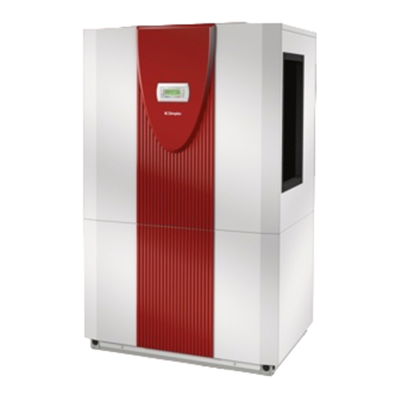
LI 9TU
LI 12TU
Luft/Wasser-
Wärmepumpe für
Innenaufstellung
Bestell-Nr. / Order no. / N
Air-to-Water
Heat Pump for
Indoor Installation
o
de commande : 452160.66.52
Montage- und
Gebrauchsanweisung
Installation and
Operating Instructions
Instructions d'installation
et d'utilisation
Pompe à chaleur
air-eau pour
installation
intérieure
FD 9205
Kapitel
Inhaltsverzeichnis

Verwandte Anleitungen für Dimplex LI 12TU


Inhaltszusammenfassung für Dimplex LI 12TU
- Seite 1 LI 9TU LI 12TU Montage- und Gebrauchsanweisung Installation and Operating Instructions Instructions d’installation et d’utilisation Luft/Wasser- Air-to-Water Pompe à chaleur Wärmepumpe für Heat Pump for air-eau pour Innenaufstellung Indoor Installation installation intérieure Bestell-Nr. / Order no. / N de commande : 452160.66.52...
-
Seite 3: Inhaltsverzeichnis
LI 9TU - LI 12TU Inhaltsverzeichnis Bitte sofort lesen ........................DE-2 1.1 Wichtige Hinweise ..........................DE-2 1.2 Bestimmungsgemäßer Gebrauch......................DE-2 1.3 Gesetzliche Vorschriften und Richtlinien ..................... DE-2 1.4 Energiesparende Handhabung der Wärmepumpe ................DE-2 Verwendungszweck der Wärmepumpe ..................DE-3 2.1 Anwendungsbereich ..........................DE-3 2.2 Arbeitsweise ............................ -
Seite 4: Bitte Sofort Lesen
LI 9TU - LI 12TU Bitte sofort lesen 1.3 Gesetzliche Vorschriften und Richtlinien 1.1 Wichtige Hinweise Diese Wärmepumpe ist gemäß Artikel 1, Abschnitt 2 k) der EG- Richtlinie 2006/42/EC (Maschinenrichtlinie) für den Gebrauch im ACHTUNG! häuslichen Umfeld bestimmt und unterliegt damit den Anforde- Für den Betrieb und die Wartung einer Wärmepumpe sind die rechtlichen... -
Seite 5: Verwendungszweck Der Wärmepumpe
LI 9TU - LI 12TU Verwendungszweck der 2.3 Funktionsbeschreibung Wärmepumpe integrierte Wärmemengenzählung 2.1 Anwendungsbereich Die Leistungsvorgaben des Verdichterherstellers bei unter- schiedlichen Drucklagen sind in der Wärmepumpen-Software Die Luft/Wasser-Wärmepumpe ist ausschließlich für die Erwär- hinterlegt. Zur Ermittlung der aktuellen Drucklage sind im Kälte- mung von Heizungswasser vorgesehen. -
Seite 6: Schaltkasten
LI 9TU - LI 12TU 3.2 Schaltkasten 4.2 Gebäudeleittechnik Der Schaltkasten befindet sich in der Wärmepumpe. Nach Ab- Der Wärmepumpenmanager kann durch die Ergänzung der je- nahme der unteren Frontabdeckung und dem Lösen der sich weiligen Schnittstellen-Steckkarte an ein Netzwerk eines Gebäu- rechts oben befindenden Befestigungsschraube kann der deleitsystems angeschlossen werden. -
Seite 7: Aufstellung
LI 9TU - LI 12TU Öffnen des Deckels Schließen des Deckels Im Aufstellraum dürfen zu keiner Jahreszeit Frost oder höhere Temperaturen als 35°C auftreten. Nach dem Transport ist die Transportsicherung im Gerät am Das Gerät sollte nie in Räumen mit hoher Luftfeuchtigkeit aufge- Boden beidseitig zu entfernen. -
Seite 8: Montage
LI 9TU - LI 12TU Montage Wird ein anderer als der als Zubehör erhältliche Luftkanal ver- wendet, ist drauf zu achten, dass die innere Querschnittsfläche von Luftansaug- und Luftausblasseite durch den Luftkanal nicht 7.1 Allgemein verringert wird. Für die Abdichtung zur Wärmepumpe können die mitgelieferten "Ringdichtungen klein und groß"... -
Seite 9: Heizungsseitiger Anschluss
LI 9TU - LI 12TU 7.3 Heizungsseitiger Anschluss Frostschutz Bei Wärmepumpen, die frostgefährdet aufgestellt sind, sollte Die heizungsseitigen Anschlüsse an der Wärmepumpe sind mit eine manuelle Entleerung (siehe Bild) vorgesehen werden. So- 1¼" Außengewinde versehen. Beim Anschluss an die Wärme- fern Wärmepumpenmanager und Heizungsumwälzpumpe be-... -
Seite 10: Montage Der Anlegefühler
LI 9TU - LI 12TU 7.4.4 Verteilsystem Warmwasser Kompaktverteiler und Doppelt differenzdruckloser Verteiler fun- gieren als Schnittstelle zwischen der Wärmepumpe, dem Hei- zungsverteilsystem, dem Pufferspeicher und evtl. auch dem Warmwasserspeicher. Dabei wird statt vieler Einzelkomponen- ten ein kompaktes System verwendet, um die Installation zu ver- einfachen. -
Seite 11: Inbetriebnahme
LI 9TU - LI 12TU Inbetriebnahme Die 3-adrige Versorgungsleitung für den Wärmepumpen- manager (Heizungsregler N1) wird in die Wärmepumpe geführt. 8.1 Allgemein Anschluss der Steuerleitung am Schaltblech der Wärme- pumpe über Klemmen X2: L/N/PE. Um eine ordnungsgemäße Inbetriebnahme zu gewährleisten, Die Leistungsaufnahme der Wärmepumpe entnehmen Sie... -
Seite 12: Reinigung / Pflege
LI 9TU - LI 12TU Um Störungen durch Schmutzablagerungen im Wärme- Wärmequellen- max. Temperaturspreizung austauscher der Wärmepumpe zu vermeiden, ist dafür zu sor- temperatur zwischen Heizungsvor- und gen, dass der Wärmeaustauscher in der Heizungsanlage nicht Rücklauf verschmutzen kann. Zum Schutz des Verdampfers ist im An- saugkanal ein Vogelschutzgitter mit mindestens 80% freien -20 °C... -
Seite 13: Reinigung Luftseite
LI 9TU - LI 12TU 11 Außerbetriebnahme / 9.3 Reinigung Luftseite Entsorgung Luftkanäle, Verdampfer, Lüfter und Kondensatablauf sind vor der Heizperiode von Verunreinigungen (Blätter, Zweige usw.) zu rei- nigen. Dazu ist die Wärmepumpe an der Seite zuerst unten und Bevor die Wärmepumpe ausgebaut wird, ist die Maschine span- dann oben zu öffnen. -
Seite 14: Geräteinformation
LI 9TU - LI 12TU 12 Geräteinformation Typ- und Verkaufsbezeichnung LI 9TU LI 12TU Bauform Wärmequelle Luft Luft Ausführung Universal Universal Regler WPM EconPlus integriert WPM EconPlus integriert Wärmemengenzählung integriert integriert Aufstellungsort Innen Innen Leistungsstufen Einsatzgrenzen Heizwasser-Vorlauf / -Rücklauf °C bis 60 ±... - Seite 15 LI 9TU - LI 12TU Sonstige Ausführungsmerkmale Abtauart Kreislaufumkehr Kreislaufumkehr Frostschutz Kondensatwanne / Wasser im Gerät gegen Einfrieren geschützt max. Betriebsüberdruck (Wärmequelle/Wärmesenke) Heizleistung / Leistungszahl EN 14511 EN 14511 Wärmeleistung / Leistungszahl bei A-7 / W35 kW / --- 5,4 / 3,0...
-
Seite 16: Garantieurkunde
LI 9TU - LI 12TU 13 Garantieurkunde Eine Verlängerung der Garantie auf 60 Monate für Heizungs-Wärme- pumpe und zentrale Wohnungslüftungsgeräte ab Inbetriebnahmeda- tum, jedoch maximal 72 Monate ab Auslieferung Werk bzw. 78 Mo- Glen Dimplex Deutschland GmbH nate ab Fertigungsdatum, wird gemäß den nachfolgenden Bedingungen gewährt: Voraussetzung für die Übernahme der ver-... - Seite 30 LI 9TU - LI 12TU EN-14 452160.66.52 · FD 9205 www.dimplex.de...
- Seite 53 LI 9TU - LI 12TU 3.3 Last / Load / Charge www.dimplex.de 452160.66.52 · FD 9205 A-IX...
- Seite 54 LI 9TU - LI 12TU 3.4 Anschlussplan / Circuit Diagram / Schéma électrique 452160.66.52 · FD 9205 www.dimplex.de...
- Seite 55 LI 9TU - LI 12TU 3.5 Anschlussplan / Circuit Diagram / Schéma électrique www.dimplex.de 452160.66.52 · FD 9205 A-XI...
- Seite 56 LI 9TU - LI 12TU 3.6 Legende / Legend / Légende Brücke EVU-Sperre, muss eingelegt werden, wenn Utility block (EVU) bridge must be inserted if no Pont de blocage de la société d'électricité, à insérer kein EVU-Sperrschütz vorhanden ist utility blocking contactor is present en absence de contacteur de blocage de la société...
- Seite 57 LI 9TU - LI 12TU Drucksensor Kältekreis - Niederdruck pO Pressure sensor for refrigerating circuit - low Capteur de pression circuit réfrigérant - basse pressure pO pression pO Drucksensor Kältekreis - Hochdruck pc Pressure sensor for refrigerating circuit - high Capteur de pression circuit réfrigérant - haute...
-
Seite 58: Hydraulische Prinzipschemen / Hydraulic Plumbing Diagrams / Schémas Hydrauliques
LI 9TU - LI 12TU 4 Hydraulische Prinzipschemen / Hydraulic Plumbing Diagrams / Schémas hydrauliques 4.1 Monoenergetische Anlage mit einem Heizkreis und Warmwasserbereitung / Mono energy system with one heating circuit and domestic hot water preparation / Installation mono-énergétique avec un circuit de chauffage et production d'eau chaude sanitaire A-XIV 452160.66.52 ·... - Seite 59 LI 9TU - LI 12TU 4.2 Legende / Legend / Légende Absperrventil Shutoff valve Vanne d’arrêt Sicherheitsventilkombination Safety valve combination Jeu de vannes de sécurité Umwälzpumpe Circulating pump Circulateur Ausdehnungsgefäß Expansion vessel Vase d’expansion Vanne commandée par Raumtemperaturgesteuertes Ventil Room temperature-controlled valve température ambiante...
-
Seite 60: Konformitätserklärung / Declaration Of Conformity / Déclaration De Conformité
LI 9TU - LI 12TU 5 Konformitätserklärung / Declaration of Conformity / Déclaration de conformité EG - Konformitätserklärung EC Declaration of Conformity Déclaration de conformité CE Der Unterzeichnete Glen Dimplex Deutschland GmbH The undersigned Geschäftsbereich Dimplex L’entreprise soussignée, Am Goldenen Feld 18 D - 95326 Kulmbach bestätigt hiermit, dass das (die) - Seite 61 LI 9TU - LI 12TU www.dimplex.de 452160.66.52 · FD 9205 A-XVII...
- Seite 62 LI 9TU - LI 12TU A-XVIII 452160.66.52 · FD 9205 www.dimplex.de...
- Seite 63 LI 9TU - LI 12TU www.dimplex.de 452160.66.52 · FD 9205 A-XIX...
- Seite 64 Glen Dimplex Deutschland GmbH Irrtümer und Änderungen vorbehalten. Geschäftsbereich Dimplex Subject to alterations and errors. Am Goldenen Feld 18 Sous réserve d’erreurs et modifications. D-95326 Kulmbach +49 (0) 9221 709 565 www.dimplex.de...