Dimplex LI 11TES Gebrauchsanweisung
Vorschau ausblenden
Andere Handbücher für LI 11TES:
- Handbuch (134 Seiten) ,
- Montageanweisung (64 Seiten) ,
- Montage- und gebrauchsanweisung (72 Seiten)
Inhaltsverzeichnis
Verfügbare Sprachen
Verfügbare Sprachen
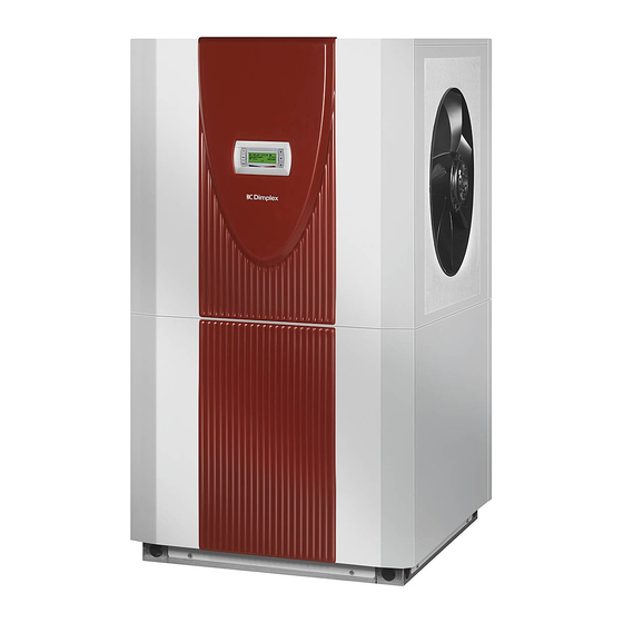
LI 11TES
Luft/Wasser-
Wärmepumpe für
Innenaufstellung
Bestell-Nr. / Order no. / N
Air-to-Water
Heat Pump for
Indoor Installation
o
de commande : 452161.66.03
Montage- und
Gebrauchsanweisung
Installation and
Operating Instructions
Instructions d'installation
et d'utilisation
Pompe à chaleur
air-eau pour
installation
intérieure
FD 9203
Kapitel
Inhaltsverzeichnis

Verwandte Anleitungen für Dimplex LI 11TES


Inhaltszusammenfassung für Dimplex LI 11TES
- Seite 1 LI 11TES Montage- und Gebrauchsanweisung Installation and Operating Instructions Instructions d’installation et d’utilisation Luft/Wasser- Air-to-Water Pompe à chaleur Wärmepumpe für Heat Pump for air-eau pour Innenaufstellung Indoor Installation installation intérieure Bestell-Nr. / Order no. / N de commande : 452161.66.03...
-
Seite 3: Inhaltsverzeichnis
LI 11TES Inhaltsverzeichnis Bitte sofort lesen ........................DE-2 1.1 Wichtige Hinweise ..........................DE-2 1.2 Bestimmungsgemäßer Gebrauch......................DE-2 1.3 Gesetzliche Vorschriften und Richtlinien ..................... DE-2 1.4 Energiesparende Handhabung der Wärmepumpe ................DE-2 Verwendungszweck der Wärmepumpe ..................DE-3 2.1 Anwendungsbereich ..........................DE-3 2.2 Arbeitsweise ............................ -
Seite 4: Bitte Sofort Lesen
LI 11TES Bitte sofort lesen 1.3 Gesetzliche Vorschriften und Richtlinien 1.1 Wichtige Hinweise Diese Wärmepumpe ist gemäß Artikel 1, Abschnitt 2 k) der EG- Richtlinie 2006/42/EC (Maschinenrichtlinie) für den Gebrauch im ACHTUNG! häuslichen Umfeld bestimmt und unterliegt damit den Anforde- Für den Betrieb und die Wartung einer Wärmepumpe sind die rechtlichen... -
Seite 5: Verwendungszweck Der Wärmepumpe
LI 11TES Verwendungszweck der Lieferumfang Wärmepumpe 3.1 Grundgerät 2.1 Anwendungsbereich Die Wärmepumpe wird in Kompaktbauweise geliefert und enthält unten aufgeführte Bauteile. Die Luft/Wasser-Wärmepumpe ist ausschließlich für die Erwär- Der Kältekreis ist „hermetisch geschlossen“ und enthält das vom mung von Heizungswasser vorgesehen.Sie kann in vorhande- Kyoto-Protokoll erfasste fluorierte Kältemittel R410A mit einem... -
Seite 6: Schaltkasten
LI 11TES 3.2 Schaltkasten 4.3 Wärmemengenzähler WMZ Der Schaltkasten befindet sich in der Wärmepumpe. Nach Ab- 4.3.1 Allgemeine Beschreibung nahme der unteren Frontabdeckung und dem Lösen der sich rechts oben befindenden Befestigungsschraube kann der Der Wärmemengenzähler (WMZ 25/32) dient dazu, die angege- Schaltkasten herausgeklappt werden. -
Seite 7: Transport
LI 11TES Transport Nach dem Transport ist die Transportsicherung im Gerät am Boden beidseitig zu entfernen. ACHTUNG! Die Wärmepumpe darf beim Transport nur bis zu einer Neigung von 45° (in jeder Richtung) gekippt werden. Der Transport zum endgültigen Aufstellungsort sollte mit Holz- rost erfolgen. -
Seite 8: Kondensatleitung
LI 11TES 6.2 Kondensatleitung Das im Betrieb anfallende Kondenswasser muss frostfrei abge- leitet werden. Um einen einwandfreien Abfluss zu gewährleisten, muss die Wärmepumpe waagerecht stehen. Das Kondenswas- serrohr muss mindestens einen Durchmesser von 50 mm haben und muss frostsicher in den Abwasserkanal geführt werden. -
Seite 9: Wechsel Der Luftrichtung
LI 11TES 7.2.2 Wechsel der Luftrichtung Durch Umsetzen des Lüfters ist es möglich, die Luftrichtung des Gerätes umzukehren. Durch den Umbau veränderte Gebrauchseigenschaften bezüg- lich Luftführung und Schallausbreitung sind bei der Anlagenpla- nung zu berücksichtigen. Weitere Angaben in dieser Anleitung bezogen auf Ansaug- und Ausblasöffnung bleiben unverändert... -
Seite 10: Heizungsseitiger Anschluss
LI 11TES 7.3 Heizungsseitiger Anschluss Frostschutz Bei Wärmepumpen, die frostgefährdet aufgestellt sind, sollte Die heizungsseitigen Anschlüsse an der Wärmepumpe sind mit eine manuelle Entleerung (siehe Bild) vorgesehen werden. So- 1¼" Außengewinde versehen. Beim Anschluss an die Wärme- fern Wärmepumpenmanager und Heizungsumwälzpumpe be- pumpe muss an den Übergängen mit einem Schlüssel gegenge-... -
Seite 11: Temperaturfühler
LI 11TES 7.4 Temperaturfühler 7.4.2 Montage des Außentemperaturfühlers Folgende Temperaturfühler sind bereits eingebaut bzw. müssen zusätzlich montiert werden: Der Temperaturfühler muss so angebracht werden, dass sämtli- che Witterungseinflüsse erfasst werden und der Messwert nicht Außentemperatur (R1) beigelegt verfälscht wird. -
Seite 12: Elektrischer Anschluss
LI 11TES 7.5 Elektrischer Anschluss Das EVU-Sperrschütz (K22) mit 3 Hauptkontakten (1/3/5 // 2/4/6) und einem Hilfskontakt (Schließer 13/14) ist entsprechend der Wärmepumpenleistung auszulegen und 7.5.1 Allgemein bauseits beizustellen. Der Schließer-Kontakt des EVU-Sperrschütz (13/14) wird Bei der Inbetriebnahme sind die länderspezifischen sowie die von Klemmleiste X3/G zur Steckerklemme N1-J5/ID3 einschlägigen VDE-Sicherheitsbestimmungen, insbesondere... -
Seite 13: Inbetriebnahme
LI 11TES Inbetriebnahme Wärmequellen- max. Temperaturspreizung temperatur zwischen Heizungsvor- und 8.1 Allgemein Rücklauf -20° C -15° C Um eine ordnungsgemäße Inbetriebnahme zu gewährleisten, -14° C -10° C sollte diese von einem vom Werk autorisierten Kundendienst -9° C -5° C durchgeführt werden. Unter bestimmten Bedingungen ist damit -4°... -
Seite 14: Reinigung / Pflege
LI 11TES Reinigung / Pflege 9.3 Reinigung Luftseite Luftkanäle, Verdampfer, Lüfter und Kondensatablauf sind vor der 9.1 Pflege Heizperiode von Verunreinigungen (Blätter, Zweige usw.) zu rei- nigen. Dazu ist die Wärmepumpe an der Frontseite zuerst unten Vermeiden Sie zum Schutz des Lackes das Anlehnen und Able- und dann oben zu öffnen. -
Seite 15: Geräteinformation
LI 11TES 12 Geräteinformation Typ- und Verkaufsbezeichnung LI 11TES Bauform Wärmequelle Luft Ausführung Universal Regler WPM 2007 integriert Wärmemengenzählung optional (als Zubehör) Aufstellungsort Innen Leistungsstufe Einsatzgrenzen Heizwasser-Vorlauf /-Rücklauf ° C bis 60 ± 2 / ab 18 Luft ° C... - Seite 16 LI 11TES Entspricht den europäischen Sicherheitsbestimmungen Sonstige Ausführungsmerkmale Abtauart Kreislaufumkehr Frostschutz Kondensatwanne / Wasser im Gerät gegen Einfrieren geschützt max. Betriebsüberdruck (Wermesenke) Heizleistung / Leistungszahlen EN 14511 Wärmeleistung / Leistungszahl Leistungstufe bei A-7 / W35 kW / --- 7,0 / 3,0...
-
Seite 17: Garantieurkunde
Bei einer Haftung nach § 478 BGB wird die Haftung des Lieferers auf die Servicepauschalen des Lieferers als Höchstbetrag beschränkt. Glen Dimplex Deutschland GmbH Garantieurkunde Systemtechnik Eine Verlängerung der Garantie auf 36 Monate für Heizungs-Wärme- (Warmwasser-Wärmepumpen, Heizungs-Wärmepumpen, pumpe und zentrale Wohnungslüftungsgeräte ab Inbetriebnahme-... - Seite 18 LI 11TES DE-2 452161.66.03 · FD 9203 www.dimplex.de...
- Seite 54 LI 11TES 3.2 Last / Load / Charge A-VI 452161.66.03 · FD 9203 www.dimplex.de...
- Seite 55 LI 11TES 3.3 Anschlussplan / Circuit Diagram / Schéma électrique www.dimplex.de 452161.66.03 · FD 9203 A-VII...
- Seite 56 LI 11TES 3.4 Legende / Legend / Légende Brücke EVU-Sperre: muss eingelegt werden, wenn Utility block bridge: Must be inserted if no utility Pont de blocage de la société d'électricité : à insé- kein EVU-Sperrschütz vorhanden ist( Kontakt offen blocking contactor is present (open contact = utility rer si aucun contacteur de blocage de la société...
- Seite 57 LI 11TES Klemmenleiste: Einspeisung Terminal strip: Infeed Bornier distributeur : Alimentation Klemmenleiste: Spannung = 230VAC Terminal strip: Voltage = 230 VAC Bornier distributeur : Tension = 230 VAC Klemmenleiste: Kleinspannung < 25VAC Terminal strip: extra-low voltage < 25VAC Bornier distributeur : Faible tension < 25 VAC...
-
Seite 58: Hydraulische Prinzipschemen / Hydraulic Plumbing Diagrams / Schémas Hydrauliques
LI 11TES 4 Hydraulische Prinzipschemen / Hydraulic Plumbing Diagrams / Schémas hydrauliques 4.1 Monoenergetische Anlage mit einem Heizkreis / Mono energy system with one heating circuits / Installation mono-énergétique avec un circuits de chauffage 452161.66.03 · FD 9203 www.dimplex.de... -
Seite 59: Monoenergetische Anlage Mit Zwei Heizkreisen
LI 11TES 4.2 Monoenergetische Anlage mit zwei Heizkreisen und Warmwasserbereitung / Mono energy system with two heating circuits and domestic hot water preparation / Installation mono- énergétique avec deux circuits de chauffage et production d'eau chaude sanitaire www.dimplex.de 452161.66.03 · FD 9203... - Seite 60 LI 11TES 4.3 Bivalente Anlage mit zwei Heizkreisen und Warmwasserbereitung / Bivalent system with two heating circuits and domestic hot water preparation / Installation bivalente avec deux circuits de chauffage et production d’eau chaude sanitaire A-XII 452161.66.03 · FD 9203...
-
Seite 62: Konformitätserklärung / Declaration Of Conformity / Déclaration De Conformité
5 Konformitätserklärung / Declaration of Conformity / Déclaration de conformité EG - Konformitätserklärung EC Declaration of Conformity Déclaration de conformité CE Der Unterzeichnete Glen Dimplex Deutschland GmbH The undersigned Geschäftsbereich Dimplex Am Goldenen Feld 18 D - 95326 Kulmbach bestätigt hiermit, dass das (die) hereby certifies that the following certifie par la présente que le(s) - Seite 63 LI 11TES www.dimplex.de 452161.66.03 · FD 9203 A-XV...
- Seite 64 Glen Dimplex Deutschland GmbH Irrtümer und Änderungen vorbehalten. Geschäftsbereich Dimplex Subject to alterations and errors. Am Goldenen Feld 18 Sous réserve d’erreurs et modifications. D-95326 Kulmbach +49 (0) 9221 709 565 www.dimplex.de...