Herunterladen Inhalt Inhalt Diese Seite drucken
SICK T 4000 Compact Betriebsanleitung
Vorschau ausblenden Andere Handbücher für T 4000 Compact:
Inhaltsverzeichnis

Werbung

Verfügbare Sprachen
  • DE

Verfügbare Sprachen

  • DEUTSCH, seite 1
D
Betriebsanleitung
Sicherheitssensor T 4000 Compact
D
E
F
GB
I
T 4 0 0 0 C o m p a c t
S a f e t y S e n s o r
8 009 212/O591/04-05-04 • © SICK AG • Industrial Safety Systems • Deutschland • Alle Rechte vorbehalten
1

Werbung

Inhaltsverzeichnis
loading

Inhaltszusammenfassung für SICK T 4000 Compact

  • Seite 1 T 4 0 0 0 C o m p a c t S a f e t y S e n s o r 8 009 212/O591/04-05-04 • © SICK AG • Industrial Safety Systems • Deutschland • Alle Rechte vorbehalten...
  • Seite 2 Bescheinigungs-Nr. 00172 Pages: 27 - 38 Page: 39 - 50 Pagina: 51 - 62 LISTED IND.CONT.EQ. 7C77 For use in class 2 circuits 8 009 212/O591/04-05-04 • © SICK AG • Industrial Safety Systems • Deutschland • Alle Rechte vorbehalten...
  • Seite 3: Inhaltsverzeichnis

    Umstellen der Anfahrrichtung Systembeschreibung Lernfunktion für Betätiger System-Zustandstabelle Kontrolle und Wartung Ansprechbereich Technische Daten Anschluss- und Blockschaltbild Auswertegerät T 4000-2 DRNAC Betätiger T 4000-1 KBA 8 009 212/O591/04-05-04 • © SICK AG • Industrial Safety Systems • Deutschland • Alle Rechte vorbehalten...
  • Seite 4: Bestimmungsgemäßer Gebrauch

    Der Tür-Meldeausgang OUT darf nicht als Sicher- heitsausgang verwendet werden. Sicherheitsverriegelungen erfüllen Personenschutz- Funktionen. Unsachgemäßer Einbau oder Manipu- lationen können zu schweren Verletzungen von Per- sonen führen. 8 009 212/O591/04-05-04 • © SICK AG • Industrial Safety Systems • Deutschland • Alle Rechte vorbehalten...
  • Seite 5: Elektrischer Anschluss

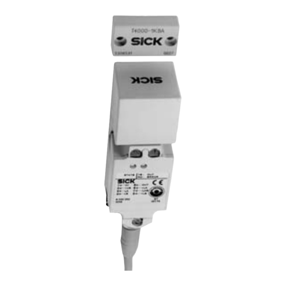
    Lesekopf mit Auswertegerät STATE YE OUT RD ERROR T4000-2DRNAC 14,5 M12x1 Codierter Betätiger Lesekopf mit Auswertegerät STATE YE OUT RD ERROR T4000-2DRNAC 14,5 M12x1 8 009 212/O591/04-05-04 • © SICK AG • Industrial Safety Systems • Deutschland • Alle Rechte vorbehalten...
  • Seite 6: Umstellen Der Anfahrrichtung

    Ansicht auf Steckseite des Gerätesteckers Der Schirm der Anschlussleitung ist über die Rän- Klemmkörper delmutter des M12-Steckverbinders mit der Schirm- feder der Sicherheitsverriegelung intern verbunden. 8 009 212/O591/04-05-04 • © SICK AG • Industrial Safety Systems • Deutschland • Alle Rechte vorbehalten...
  • Seite 7: Systembeschreibung

    Fällen wird ein Lernvorgang mit der Dauer von 60 Sekunden eingeleitet, der letzte Betätigercode bleibt jedoch im Speicher aktiv (siehe Zustands- tabelle), es wird kein neuer Code erlernt. 8 009 212/O591/04-05-04 • © SICK AG • Industrial Safety Systems • Deutschland • Alle Rechte vorbehalten...
  • Seite 8: System-Zustandstabelle

    = 0 oder 24 Volt bzw. Türe auf oder zu Hinweis: Das Auswertegerät kann nur mit dem jeweils zuletzt gelernten Betätiger betrieben werden. 8 009 212/O591/04-05-04 • © SICK AG • Industrial Safety Systems • Deutschland • Alle Rechte vorbehalten...
  • Seite 9: Kontrolle Und Wartung

    Um nicht in den Ansprechbereich der Nebenkeulen zu gelangen, muss bei seitlicher Anfahrrichtung von Betätiger und Sicherheitsverriegelung ein Mindestabstand von s = 3 mm eingehalten werden. Werte siehe Technische Daten 8 009 212/O591/04-05-04 • © SICK AG • Industrial Safety Systems • Deutschland • Alle Rechte vorbehalten...
  • Seite 10: Anschluss- Und Blockschaltbild

    5/GY 4/YE 6/PK (GY) E2 Eingang (BN) 3/GN 7/BU + 24 V DC 2/BN 1/WH (WH) Ansicht auf Steckseite der 8-poligen Leitungsdose 10 8 009 212/O591/04-05-04 • © SICK AG • Industrial Safety Systems • Deutschland • Alle Rechte vorbehalten...
  • Seite 11: Auswertegerät T 4000-2 Drnac

    (Betätiger nicht im (Betätiger erkannt) Ansprechbereich) Lesekopf Betätiger Lesekopf + LA + LA + LB + LB 24 V 24 V 8 009 212/O591/04-05-04 • © SICK AG • Industrial Safety Systems • Deutschland • Alle Rechte vorbehalten 11...
  • Seite 12: Technische Daten

    Die Verweildauer ist die Zeit, in der sich der Betätiger innerhalb oder außerhalb des Ansprechbereichs befinden muss Die Werte gelten für nichtbündigen Einbau des Betätigers 12 8 009 212/O591/04-05-04 • © SICK AG • Industrial Safety Systems • Deutschland • Alle Rechte vorbehalten...
  • Seite 13: Betätiger T 4000-1Kba

    - sie nicht als mechanischer Anschlag verwendet werden. - sie formschlüssig mit der Schutzeinrichtung verbunden sind z. B. durch die Verwendung der beiliegen- den Sicherheitsschrauben. 8 009 212/O591/04-05-04 • © SICK AG • Industrial Safety Systems • Deutschland • Alle Rechte vorbehalten 13...
  • Seite 14 Betriebsanleitung Sicherheitssensor T 4000 Compact 14 8 009 212/O591/04-05-04 • © SICK AG • Industrial Safety Systems • Deutschland • Alle Rechte vorbehalten...
  • Seite 15 Tabla de estados del sistema Control y mantenimiento Rango operativo Datos técnicos Diagrama de conexiones y de bloques Aparato evaluador T 4000-2 DRNAC Actuador T 4000-1KBA 8 009 212/O591/04-05-04 • © SICK AG • Industrial Safety Systems • Alemania • Reservados todos los derechos...
  • Seite 16: Aplicación De Acuerdo A La Finalidad

    La función de los interruptores de seguridad es ga- rantizar la seguridad de las personas. Su montaje incorrecto o bien su manipulación, puede causar graves lesiones a personas. 8 009 212/O591/04-05-04 • © SICK AG • Industrial Safety Systems • Alemania • Reservados todos los derechos...
  • Seite 17: Conexión Eléctrica

    RD ERROR T4000-2DRNAC 14,5 M12x1 Actuador codificado Cabeza de lectura con aparato de evaluación STATE YE OUT RD ERROR T4000-2DRNAC 14,5 M12x1 8 009 212/O591/04-05-04 • © SICK AG • Industrial Safety Systems • Alemania • Reservados todos los derechos...
  • Seite 18: Ajuste De La Dirección De Activación De La Cabeza

    La pantalla del cable de conexión ha de unirse internamente a través de la tuerca moleteada del Carcasa de fijación conector M12 con el blindado del interruptor de seguridad. 8 009 212/O591/04-05-04 • © SICK AG • Industrial Safety Systems • Alemania • Reservados todos los derechos...
  • Seite 19: Descripción Del Sistema

    Durante un proceso de aprendizaje, las salidas de 8 009 212/O591/04-05-04 • © SICK AG • Industrial Safety Systems • Alemania • Reservados todos los derechos...
  • Seite 20: Tabla De Estados Del Sistema

    = 0 ó 24 voltios o bien puerta abierta o cerrada Indicación: El aparato evaluador opera únicamente con el actuador aprendido en último lugar. 8 009 212/O591/04-05-04 • © SICK AG • Industrial Safety Systems • Alemania • Reservados todos los derechos...
  • Seite 21: Control Y Mantenimiento

    Debe mantenerse una distancia mínima de S = 3 mm, para prevenir en caso de aproximación lateral, la entrada de lóbulos secundarios dentro del rango de operación. Sobre valores ver Características Técnicas 8 009 212/O591/04-05-04 • © SICK AG • Industrial Safety Systems • Alemania • Reservados todos los derechos...
  • Seite 22: Diagrama De Conexiones Y De Bloques

    (GY) E2 entrada (BN) 3/GN 7/BU + 24 V DC 2/BN 1/WH (WH) Vista del lado de enchufe del conector del cable 8 009 212/O591/04-05-04 • © SICK AG • Industrial Safety Systems • Alemania • Reservados todos los derechos...
  • Seite 23: Aparato Evaluador T 4000-2 Drnac

    Cabeza Cabeza Actuador de lectura de lectura + LA + LA + LB + LB 24 V 24 V 8 009 212/O591/04-05-04 • © SICK AG • Industrial Safety Systems • Alemania • Reservados todos los derechos...
  • Seite 24: Datos Técnicos

    El tiempo de espera es el periodo en el que se debe encontrar el actuador dentro o fuera de la zona de reacción. Los valores son válidos para montaje no enrasado del accionador. 8 009 212/O591/04-05-04 • © SICK AG • Industrial Safety Systems • Alemania • Reservados todos los derechos...
  • Seite 25: Actuador T 4000-1Kba

    - no puedan ser utilizados como tope mecánico. - la unión con el dispositivo de protección sea positiva, por ejemplo, utilizando los tornillos de seguridad adjuntos. 8 009 212/O591/04-05-04 • © SICK AG • Industrial Safety Systems • Alemania • Reservados todos los derechos...
  • Seite 26 Instrucciones de uso Sensor de seguridad T 4000 Compact 8 009 212/O591/04-05-04 • © SICK AG • Industrial Safety Systems • Alemania • Reservados todos los derechos...
  • Seite 27 Tableau des états du système Contrôle et entretien Zone de déclenchement Caractéristiques techniques Schéma de raccordement Analyseur T 4000-2 DRNAC Actionneur T 4000-1KBA 8 009 212/O591/04-05-04 • © SICK AG • Industrial Safety Systems • Allemagne • Tous droits réservés...
  • Seite 28: Utilisation Conforme

    Les interrupteurs de sécurité remplissent des fonc- tions de protection des personnes. Un montage in- correct ou des manipulations peuvent être à l’origine de blessures graves. 8 009 212/O591/04-05-04 • © SICK AG • Industrial Safety Systems • Allemagne • Tous droits réservés...
  • Seite 29: Raccordement Électrique

    STATE YE OUT RD ERROR T4000-2DRNAC 14,5 M12x1 Actionneur codé Tête de lecture avec analyseur STATE YE OUT RD ERROR T4000-2DRNAC 14,5 M12x1 8 009 212/O591/04-05-04 • © SICK AG • Industrial Safety Systems • Allemagne • Tous droits réservés...
  • Seite 30: Changement Du Sens D'attaque

    Le blindage du câble est relié à la source de Borne blindage de l’interrupteur de sécurité par le biais de l’écrou moleté du connecteur à fiches M12. 8 009 212/O591/04-05-04 • © SICK AG • Industrial Safety Systems • Allemagne • Tous droits réservés...
  • Seite 31: Description Du Système

    (voir le tableau des états). Un nouveau code n’est pas appris. 8 009 212/O591/04-05-04 • © SICK AG • Industrial Safety Systems • Allemagne • Tous droits réservés...
  • Seite 32: Tableau Des États Du Système

    1 = 24 volts x = 0 ou 24 volts et porte ouverte ou fermée Remarque: L’appareil ne peut fonctionner qu’avec le dernier actionneur appris. 8 009 212/O591/04-05-04 • © SICK AG • Industrial Safety Systems • Allemagne • Tous droits réservés...
  • Seite 33: Contrôle Et Entretien

    Afin de ne pas entrer dans la zone de repose des lobes secondaires, une distance minimale de s = 3 mm doit être respectée entre l’actionneur et l’interrupteur de sécurité dans le cas d’une approche latérale. Pour les valeurs, voir les caractéristiques techniques 8 009 212/O591/04-05-04 • © SICK AG • Industrial Safety Systems • Allemagne • Tous droits réservés...
  • Seite 34: Schéma De Raccordement

    8/RD 5/GY 4/YE 6/PK (GY) E2 Entrée (BN) 3/GN 7/BU + 24 V DC 2/BN 1/WH (WH) Vue du côte connecteur de câble 8 009 212/O591/04-05-04 • © SICK AG • Industrial Safety Systems • Allemagne • Tous droits réservés...
  • Seite 35: Analyseur T 4000-2 Drnac

    Tête de Tête de Actionneur lecture lecture + LA + LA + LB + LB 24 V 24 V 8 009 212/O591/04-05-04 • © SICK AG • Industrial Safety Systems • Allemagne • Tous droits réservés...
  • Seite 36: Caractéristiques Techniques

    La durée de contact correspond à la période pendant laquelle l’actionneur doit se trouver à l’intérieur ou à l’extérieur de la zone de détection. Ces valeurs s’appliquent pour un montage non affleurant de l’actionneur. 8 009 212/O591/04-05-04 • © SICK AG • Industrial Safety Systems • Allemagne • Tous droits réservés...
  • Seite 37: Actionneur T 4000-1Kba

    - ils ne soient pas utilisés comme butée mécanique. - ils soient reliés par engagement positif au dispositif de protection, par ex. par l’utilisation des vis de sécurité jointes. 8 009 212/O591/04-05-04 • © SICK AG • Industrial Safety Systems • Allemagne • Tous droits réservés...
  • Seite 38 Mode d’emploi Capteur de sécurité T 4000 Compact 8 009 212/O591/04-05-04 • © SICK AG • Industrial Safety Systems • Allemagne • Tous droits réservés...
  • Seite 39 System status table Inspection and maintenance Operating range Technical data Connection and block diagram Evaluation unit T 4000-2 DRNAC Actuator type series T 4000-1KBA 8 009 212/O591/04-05-04 • © SICK AG • Industrial Safety Systems • Germany • All rights reserved...
  • Seite 40: Correct Use

    The door signal output OUT must not be used as a safety output. Safety interlocks perform personnel safety functions. Incorrect installation or tampering may lead to serious injury. 8 009 212/O591/04-05-04 • © SICK AG • Industrial Safety Systems • Germany • All rights reserved...
  • Seite 41: Electrical Connection

    STATE YE OUT RD ERROR T4000-2DRNAC 14,5 M12x1 Coded actuator Read head with evaluation unit STATE YE OUT RD ERROR T4000-2DRNAC 14,5 M12x1 8 009 212/O591/04-05-04 • © SICK AG • Industrial Safety Systems • Germany • All rights reserved...
  • Seite 42: Adjusting Direction Of Approach

    The shield of the connecting cable is internally Clamping unit connected to the shielded core of the safety inter- lock via the knurled nut of the M12 connector. 8 009 212/O591/04-05-04 • © SICK AG • Industrial Safety Systems • Germany • All rights reserved...
  • Seite 43: System Description

    Teach-In Operation lasting 60 seconds is in- itiated, but the last actuator code remains active in memory (see Status table); no new code is taught. 8 009 212/O591/04-05-04 • © SICK AG • Industrial Safety Systems • Germany • All rights reserved...
  • Seite 44: System Status Table

    = 0 or 24 Volt resp.door open or closed Note: The evaluation unit can be operated only with the last actuator taught. 8 009 212/O591/04-05-04 • © SICK AG • Industrial Safety Systems • Germany • All rights reserved...
  • Seite 45: Inspection And Maintenance

    A minimum distance of s = 3 mm must be maintained in the case of lateral approach in order to prevent entry into the operating range of the secondary fields. Values (see Technical Data) 8 009 212/O591/04-05-04 • © SICK AG • Industrial Safety Systems • Germany • All rights reserved...
  • Seite 46: Output Circuit

    6/PK (GY) E2 input (BN) 3/GN 7/BU + 24 V DC 2/BN 1/WH (WH) View from mating side of the 8-pole cable connector 8 009 212/O591/04-05-04 • © SICK AG • Industrial Safety Systems • Germany • All rights reserved...
  • Seite 47: Evaluation Unit T 4000-2 Drnac

    (actuator out of (actuator identified) operating range) Read Read head actuator head + LA + LA + LB + LB 24 V 24 V 8 009 212/O591/04-05-04 • © SICK AG • Industrial Safety Systems • Germany • All rights reserved...
  • Seite 48: Technical Data

    The dwell time is the period for which the actuator must remain inside or outside the operating range. The values do not apply for non-flush installation of actuator. 8 009 212/O591/04-05-04 • © SICK AG • Industrial Safety Systems • Germany • All rights reserved...
  • Seite 49: Actuator Type Series T 4000-1Kba

    Technical data) with the safety guard closed. - They are not used as a mechanical stop. - They are positively connected to the safety guard; e.g. by using adhesive. 8 009 212/O591/04-05-04 • © SICK AG • Industrial Safety Systems • Germany • All rights reserved...
  • Seite 50 Operating Instructions Safety sensor T 4000 Compact 8 009 212/O591/04-05-04 • © SICK AG • Industrial Safety Systems • Germany • All rights reserved...
  • Seite 51 Controllo e manutenzione Campo di risposta Caratteristiche tecniche Schema a blocchi e di collegamento Unità di elaborazioneT 4000-2 DRNAC Attuatore tipo T 4000-1KBA 8 009 212/O591/04-05-04 • © SICK AG • Industrial Safety Systems • Germania • Tutti i diritti riservati...
  • Seite 52: Impiego Conforme Alle Norme

    Gli interruttori di sicurezza garantiscono la protezione delle persone. Un montaggio improprio o eventuali manipolazioni possono provocare lesioni gravi. 8 009 212/O591/04-05-04 • © SICK AG • Industrial Safety Systems • Germania • Tutti i diritti riservati...
  • Seite 53: Collegamento Elettrico

    STATE YE OUT RD ERROR T4000-2DRNAC 14,5 M12x1 Azionatore codificato Testina di lettura con centralina STATE YE OUT RD ERROR T4000-2DRNAC 14,5 M12x1 8 009 212/O591/04-05-04 • © SICK AG • Industrial Safety Systems • Germania • Tutti i diritti riservati...
  • Seite 54: Modifica Della Direzione Di Azionamento

    Mediante il dado zigrinato del connettore M12, lo schermo del cavo di allacciamento è collegato internamente alla molla schermante Morsetti dell’interruttore di sicurezza. 8 009 212/O591/04-05-04 • © SICK AG • Industrial Safety Systems • Germania • Tutti i diritti riservati...
  • Seite 55: Descrizione Del Sistema

    (vedere positivo di rilevamento tramite la funzione di appren- tabella di stato), non viene appreso nessun codice dimento. nuovo. 8 009 212/O591/04-05-04 • © SICK AG • Industrial Safety Systems • Germania • Tutti i diritti riservati...
  • Seite 56: Tabella Di Stato Del Sistema

    Il dispositivo di rilevamento può essere messo in funzione soltanto con l’azionatore con cui sia stato eseguito per ultimo il ciclo di apprendimento. 8 009 212/O591/04-05-04 • © SICK AG • Industrial Safety Systems • Germania • Tutti i diritti riservati...
  • Seite 57: Controllo E Manutenzione

    = 3 mm per non pregiudicare il campo d’intervento del lobo secondario. Valori v. Caratteristiche tecniche 8 009 212/O591/04-05-04 • © SICK AG • Industrial Safety Systems • Germania • Tutti i diritti riservati...
  • Seite 58: Schema A Blocchi E Di Collegamento

    8/RD 5/GY 4/YE 6/PK (GY) E2 Ingresso (BN) 3/GN 7/BU + 24 V DC 2/BN 1/WH (WH) Lato collegameti dell’connettore del cavo 8 009 212/O591/04-05-04 • © SICK AG • Industrial Safety Systems • Germania • Tutti i diritti riservati...
  • Seite 59: Unità Di Elaborazionet 4000-2 Drnac

    Testina di Testina di Azionatore lettura lettura + LA + LA + LB + LB 24 V 24 V 8 009 212/O591/04-05-04 • © SICK AG • Industrial Safety Systems • Germania • Tutti i diritti riservati...
  • Seite 60: Caratteristiche Tecniche

    Il tempo di permanenza è il tempo in cui l’azionatore si deve trovare entro o fuori del campo d’intevento. I valori si riferiscono al montaggio non incassato dell’azionatore. 8 009 212/O591/04-05-04 • © SICK AG • Industrial Safety Systems • Germania • Tutti i diritti riservati...
  • Seite 61: Attuatore Tipo T 4000-1Kba

    - non vengano utilizzati come arresto meccanico. - siano collegati in accoppiamento con il dispositivo di protezione, ad esempio utilizzando le viti di sicurezza accluse. 8 009 212/O591/04-05-04 • © SICK AG • Industrial Safety Systems • Germania • Tutti i diritti riservati...
  • Seite 62 Istruzioni d’uso Sensore di sicurezza T 4000 Compact 8 009 212/O591/04-05-04 • © SICK AG • Industrial Safety Systems • Germania • Tutti i diritti riservati...
  • Seite 64 U S A / C a n a d a / M é x i c o Phone +1(952) 941-6780 1 800-325-7425 … tollfree E-Mail info@sickusa.com More representatives and agencies in all major industrial nations at www.sick.com SICK AG Industrial Safety Systems Waldkirch Germany www.sick.com...

Inhaltsverzeichnis