Herunterladen Inhalt Inhalt Diese Seite drucken
Inhaltsverzeichnis

Werbung

Verfügbare Sprachen

Verfügbare Sprachen

Operating Instructions
LEVEL TRANSMITTER
8137
4 ... 20 mA/HART

Werbung

Inhaltsverzeichnis
loading

Inhaltszusammenfassung für bürkert 8137

  • Seite 1 Operating Instructions LEVEL TRANSMITTER 8137 4 ... 20 mA/HART...
  • Seite 2: Inhaltsverzeichnis

    Parameter adjustment with AMS™ and PDM ..38 Saving the parameter adjustment data ... . 38 LEVEL TRANSMITTER 8137 • 4 ... 20 mA/HART...
  • Seite 3 10.2 Dimensions ....... 48 Supplementary documentation Information: Supplementary documents appropriate to the ordered version come with the delivery. You can find them listed in chapter "Product description". LEVEL TRANSMITTER 8137 • 4 ... 20 mA/HART...
  • Seite 4: About This Document

    List The dot set in front indicates a list with no implied sequence. à Action This arrow indicates a single action. Sequence Numbers set in front indicate successive steps in a procedure. LEVEL TRANSMITTER 8137 • 4 ... 20 mA/HART...
  • Seite 5: For Your Safety

    During work on and with the device the required personal protective equipment must always be worn. 2.2 Appropriate use LEVEL TRANSMITTER 8137 is a sensor for continuous level measurement. You can find detailed information on the application range in chapter "Product description".
  • Seite 6: Safety Approval Markings And Safety Tips

    The parameter adjustment of the basic sensor functions is independ- ent of the software version. The range of available functions depends on the respective software version of the individual components. The software version of LEVEL TRANSMITTER 8137 can be determined as follows: on the type label of the electronics via the indicating and adjustment module R &...
  • Seite 7: Sil Conformity

    Modifications not expressly approved by Bürkert will lead to expiry of the operating licence according to FCC/IC. LEVEL TRANSMITTER 8137 is in conformity with part 15 of the FCC directives and fulfills the RSS-210 regulations. Note the corresponding regulations for operation:...
  • Seite 8: Product Description

    Housing cover, optionally available with indicating and adjustment module The components are available in different versions. Fig. 1: LEVEL TRANSMITTER 8137 - threaded version with plastic housing Housing cover with integrated indicating and adjustment module (optional) Housing with electronics Process fitting with horn antenna Type label The type label contains the most important data for identification and...
  • Seite 9: Principle Of Operation

    LEVEL TRANSMITTER 8137 is a radar sensor in K-band (emitting Application area frequency approx. 26 GHz) for continuous level measurement. A suitable version of LEVEL TRANSMITTER 8137 is available for each area of application: The version with "thread and horn antenna with ø 40 mm (1.575 in)"...
  • Seite 10: Packaging, Transport And Storage

    3 Product description With a HART handheld The entered parameters are generally saved in LEVEL TRANS- MITTER 8137, optionally also in the indicating/adjustment module. 3.4 Packaging, transport and storage Packaging Your instrument was protected by packaging during transport. Its capacity to handle normal loads during transport is assured by a test according to DIN EN 24180.
  • Seite 11: Mounting

    The reference plane for the measuring range is the lower edge of the flange or the seal surface of the thread. Information: If the medium reaches the antenna, buildup can form on it and cause faulty measurements later on. LEVEL TRANSMITTER 8137 • 4 ... 20 mA/HART...
  • Seite 12: Mounting Preparations - Horn Antenna

    4.2 Mounting preparations - Horn antenna Information: This information applies only to special versions! LEVEL TRANSMITTER 8137 is also available in versions where the antenna has a bigger diameter than the process fitting (thread, flange). The antenna must therefore be disconnected from the process fitting before mounting.
  • Seite 13: Mounting Preparations - Parabolic Antenna

    4.3 Mounting preparations - Parabolic antenna Information: This information applies only to special versions! LEVEL TRANSMITTER 8137 is also available in versions where the antenna has a diameter larger than the process fitting (thread, flange). With such versions the antenna must be disconnected from the process fitting before mounting.
  • Seite 14: Mounting Instructions

    Parabolic antenna 4.4 Mounting instructions Horn and parabolic an- The illustrations with the following mounting instructions show a LEVEL TRANSMITTER 8137 with horn antenna. The mounting tenna instructions apply analogously also to the version with parabolic antenna. When mounting the sensor, keep a distance of at least 200 mm Mounting position (7.874 in) to the vessel wall.
  • Seite 15 Fig. 7: Vessel with conical bottom Inflowing medium Do not mount the instruments in or above the filling stream. Make sure that you detect the product surface, not the inflowing product. LEVEL TRANSMITTER 8137 • 4 ... 20 mA/HART...
  • Seite 16 Fig. 9: Recommended socket mounting If the reflective properties of the medium are good, you can mount LEVEL TRANSMITTER 8137 on sockets which are higher than the length of the antenna. You will find recommended values for socket heights in the following illustration. The socket end should be smooth and burr-free, if possible also rounded.
  • Seite 17 800 mm Fig. 10: Deviating socket dimensions Tip: LEVEL TRANSMITTER 8137 is optionally also available with antenna extension. Hence the antenna length can be selected such that the antenna end protrudes 10 mm (0.4 in) out of the socket. Sensor orientation Align the sensor in liquids as vertical as possible to the product surface to achieve optimum measuring results.
  • Seite 18 (from DK value 1.6) is pass tube) possible. Surge or bypass tubes must extend all the way down to the requested min. level, as measurement is only possible within the tube. LEVEL TRANSMITTER 8137 • 4 ... 20 mA/HART...
  • Seite 19 Vent holde max. ø 5 mm (0.2 in) If possible, the antenna diameter of the sensor should correspond to the inner diameter of the tube. With LEVEL TRANSMITTER 8137 this is approx. 40 mm (1.575 in). The sensor can be used with tube diameters between 40 …...
  • Seite 20 Marking of the polarisation direction When the sensor is mounted on a bypass tube, the distance from LEVEL TRANSMITTER 8137 to the upper tube connection should be approx. 300 mm (11.81 in) or more. In case of extremely rough tube inner walls, you should use an inserted tube (tube in tube) or a radar sensor with tube antenna.
  • Seite 21: Connecting To Power Supply

    (e. g. 1 nF, 1500 V). The low frequency potential equalisation currents are thus suppressed, but the protective effect against high frequency interfer- ence signals remains. LEVEL TRANSMITTER 8137 • 4 ... 20 mA/HART...
  • Seite 22: Connection Procedure

    10 Connect the screen to the internal ground terminal, connect the outer ground terminal with potential equalisation 11 Tighten the compression nut of the cable entry. The seal ring must completely encircle the cable 12 Screw the housing cover on LEVEL TRANSMITTER 8137 • 4 ... 20 mA/HART...
  • Seite 23: Wiring Plan, Single Chamber Housing

    Fig. 17: Electronics and connection compartment, single chamber housing Service interface Spring-loaded terminals for connection of an external indication Ground terminal for connection of the cable screen Spring-loaded terminals for voltage supply LEVEL TRANSMITTER 8137 • 4 ... 20 mA/HART...
  • Seite 24: Switch On Phase

    Fig. 18: Wiring plan, single chamber housing Voltage supply/Signal output 5.4 Switch on phase After connecting LEVEL TRANSMITTER 8137 to power supply or after Switch on phase a voltage recurrence, the instrument carries out a self-check for approx. 30 seconds: Internal check of the electronics Indication of the instrument type, the firmware as well as the...
  • Seite 25: Set Up With The Indicating And Adjustment Module

    Screw housing cover with inspection window tightly back on Removal is carried out in reverse order. The indicating and adjustment module is powered by the sensor, an additional connection is not necessary. LEVEL TRANSMITTER 8137 • 4 ... 20 mA/HART...
  • Seite 26 Fig. 19: Mounting the indicating and adjustment module Note: If you intend to retrofit the instrument with an indicating and adjustment module for continuous measured value indication, a higher cover with an inspection glass is required. LEVEL TRANSMITTER 8137 • 4 ... 20 mA/HART...
  • Seite 27: Adjustment System

    The functions of the individual keys are shown in the above illustration. Approx. 10 minutes after the last pressing of a key, an automatic reset to measured value indication is triggered. Any values not confirmed with [OK] will not be saved. LEVEL TRANSMITTER 8137 • 4 ... 20 mA/HART...
  • Seite 28: Setup Procedure

    DTM. HART mode Standard Address 0 As LEVEL TRANSMITTER 8137 is a distance measuring instrument, Parameter adjustment the distance from the sensor to the product surface is measured. To have the real product level displayed, an allocation of the measured distance to the percentage height must be made.
  • Seite 29 (with liquids); dust generation, material cones and echoes from the vessel wall (with solids). To adapt the sensor to these different conditions, you should first select "Liquid" or "Solid". LEVEL TRANSMITTER 8137 • 4 ... 20 mA/HART...
  • Seite 30 Vessel form Storage tank Information: With LEVEL TRANSMITTER 8137 with electronics version "Increased safety", "Solid" is preset as factory setting. However, the instrument should be used preferably in liquids. In such cases, the vessel form should be set to "Storage tank" during setup.
  • Seite 31 Gating out of false signals Change now? Proceed as follows: Move from the measured value display to the main menu by pushing [OK]. LEVEL TRANSMITTER 8137 • 4 ... 20 mA/HART...
  • Seite 32 Copy sensor data Copy sensor data? Reset Basic adjustment If the "Reset" is carried out, the sensor resets the values of the following functions to reset values (see chart: (sensor-specific basic adjustment) LEVEL TRANSMITTER 8137 • 4 ... 20 mA/HART...
  • Seite 33 You will find a detailed description of these menu items in the operating instructions manual "Indicating and adjustment module". Special parameters are parameters which are set customer-specifically on the service level with the adjustment software PACTware. LEVEL TRANSMITTER 8137 • 4 ... 20 mA/HART...
  • Seite 34: Menu Schematic

    Info Displayed value Display unit Scaling Lighting ▼ ▼ Scaled Volume 0 % = 0.0 l Switched off ▼ 100 % = 100.0 l Diagnostics Basic adjustment Display ▶ Diagnostics Service Info LEVEL TRANSMITTER 8137 • 4 ... 20 mA/HART...
  • Seite 35 Basic adjustment Display Diagnostics Service ▶ Info Sensor type Date of manufacture Last change using PC Sensor characteristics 4. August 2008 Software version Display now? 3.50 4. August 2008 Serial number 12345678 LEVEL TRANSMITTER 8137 • 4 ... 20 mA/HART...
  • Seite 36: Saving The Parameter Adjustment Data

    They are hence available for multiple use or service purposes. If LEVEL TRANSMITTER 8137 is equipped with an indicating and adjustment module, the most important data can be read out of the sensor into indicating and adjustment module. The procedure is described in the operating instructions manual "Indicating and...
  • Seite 37: Setup With Pactware And Other Adjustment Programs

    A detailed description is available in the online help of PACTware and the Bürkert DTMs. Note: Keep in mind that for setup of LEVEL TRANSMITTER 8137, DTM- Collection in the actual version must be used. LEVEL TRANSMITTER 8137 • 4 ... 20 mA/HART...
  • Seite 38: Parameter Adjustment With Ams™ And Pdm

    It is recommended to document or save the parameter adjustment data. They are hence available for multiple use or service purposes. The Bürkert DTM Collection and PACTware in the licensed, professional version provide suitable tools for systematic project documentation and storage. LEVEL TRANSMITTER 8137 • 4 ... 20 mA/HART...
  • Seite 39: Maintenance And Fault Rectification

    Current signal greater than 22 mA or less than 3.6 mA Electronics module defective à Exchange instrument or return instrument for repair In Ex applications, the regulations for the wiring of intrinsically safe circuits must be observed. LEVEL TRANSMITTER 8137 • 4 ... 20 mA/HART...
  • Seite 40 à Exchange instrument or return instrument for repair Reaction after fault rec- Depending on the failure reason and measures taken, the steps tification described in chapter "Set up" must be carried out again, if necessary. LEVEL TRANSMITTER 8137 • 4 ... 20 mA/HART...
  • Seite 41: Dismounting

    Correct disposal avoids negative effects to persons and environment and ensures recycling of useful raw materials. Materials: see chapter "Technical data" If you have no possibility to dispose of the old instrument professionally, please contact us concerning return and disposal. LEVEL TRANSMITTER 8137 • 4 ... 20 mA/HART...
  • Seite 42: Supplement

    Distance to the level - scaled 1.6 µA Signal resolution mA-value unchanged 20.5 mA, 22 mA, < 3.6 mA Failure signal current output (adjustable) (adjustable) 22 mA Max. output current Load see load diagram under Power supply LEVEL TRANSMITTER 8137 • 4 ... 20 mA/HART...
  • Seite 43 Step response or adjustment time Adjustable up to 1 m/min. (dependent on the Max. level change parameter adjustment) Time to output the correct level (with max. 10 % deviation) after a sudden level change. LEVEL TRANSMITTER 8137 • 4 ... 20 mA/HART...
  • Seite 44 10 mm 3 mm 0,5 m 30 m -3 mm -10 mm Fig. 22: Deviation LEVEL TRANSMITTER 8137 with horn antenna in mm, measuring range in m Incl. non-linearity, hysteresis and non-repeatability. LEVEL TRANSMITTER 8137 • 4 ... 20 mA/HART...
  • Seite 45 -3 mm 2,0 m 30 m -40 mm Fig. 23: Deviation LEVEL TRANSMITTER 8137 with parabolic antenna in mm, measuring range in m Influence of the ambient temperature to the sensor electronics 0.03 %/10 K Average temperature coefficient of the zero...
  • Seite 46 EEx-d-ia instrument Permissible residual ripple < 100 Hz < 1 V 100 Hz … 10 kHz < 10 mV Load see diagram Tested according to the regulations of German Lloyd, GL directive 2. LEVEL TRANSMITTER 8137 • 4 ... 20 mA/HART...
  • Seite 47 ATEX II 1G, 1/2G, 2G EEx ia IIC T5+ATEX II 1/2D ATEX ia + D IP6X T6 IEC ia IEC Ex ia IIC T6 Others Deviating data in Ex applications: see separate safety instructions. Depending on order specification. LEVEL TRANSMITTER 8137 • 4 ... 20 mA/HART...
  • Seite 48: Dimensions

    " ø1 " 1½" " ø1 " 2" " ø2 " 3" " ø3 " 4" Fig. 26: LEVEL TRANSMITTER 8137 - horn antenna in threaded version Standard with temperature adapter LEVEL TRANSMITTER 8137 • 4 ... 20 mA/HART...
  • Seite 49 6" 150 lb 279,4 25,4 241,3 8xø22,4 6" 150 lb 11" 1" " 8xø " " " Fig. 27: LEVEL TRANSMITTER 8137 - horn antenna in flange version Standard with temperature adapter LEVEL TRANSMITTER 8137 • 4 ... 20 mA/HART...
  • Seite 50 LEVEL TRANSMITTER 8137 - parabolic antenna in threaded version 46mm ") G1½A / 1½ NPT ø 244mm (9 ") Fig. 28: LEVEL TRANSMITTER 8137 - parabolic antenna in threaded version Standard with temperature adapter LEVEL TRANSMITTER 8137 • 4 ... 20 mA/HART...
  • Seite 51 4" 150 lb 11" 1" " 8xø " 6" 150 lb 279,4 25,4 241,3 8xø22,4 6" 150 lb Fig. 29: LEVEL TRANSMITTER 8137 - parabolic antenna in flange version Standard with temperature adapter LEVEL TRANSMITTER 8137 • 4 ... 20 mA/HART...
  • Seite 52 10 Supplement LEVEL TRANSMITTER 8137 • 4 ... 20 mA/HART...
  • Seite 53 10 Supplement LEVEL TRANSMITTER 8137 • 4 ... 20 mA/HART...
  • Seite 54 10 Supplement LEVEL TRANSMITTER 8137 • 4 ... 20 mA/HART...
  • Seite 55 10 Supplement LEVEL TRANSMITTER 8137 • 4 ... 20 mA/HART...
  • Seite 56 The smart choice of Fluid Control Systems www.burkert.com Subject to change without prior notice 32065-EN-081121...
  • Seite 57: Mise En Service

    Mise en service LEVEL TRANSMITTER 8137 4 ... 20 mA/HART...
  • Seite 58 Mise en service avec PACTware et autres programmes de configuration Raccordement du PC ......39 LEVEL TRANSMITTER 8137 • 4 ... 20 mA/HART...
  • Seite 59 10.2 Encombrement ......50 Documentation complémentaire Information: Suivant la version commandée, une documentation complémentaire fera partie de la livraison. Elle vous sera indiquée au chapitre "Description du produit". LEVEL TRANSMITTER 8137 • 4 ... 20 mA/HART...
  • Seite 60: Propos De Ce Document

    à Etape de déroulement d'une action Cette flèche indique le pas de déroulement d'une action. Chronologie de déroulement d'une action Le déroulement d'une action est numéroté dans son ordre chronolo- gique. LEVEL TRANSMITTER 8137 • 4 ... 20 mA/HART...
  • Seite 61: Pour Votre Sécurité

    Portez toujours l'équipement de protection personnel nécessaire en travaillant sur et avec l'appareil. 2.2 Définition de l'application Le LEVEL TRANSMITTER 8137 est un capteur pour la mesure de niveau continue. Vous trouverez des informations plus détaillées concernant le domaine d'application au chapitre "Description du produit".
  • Seite 62: Caractéristiques Et Remarques De Sécurité

    Vous pouvez prendre connaissance de la version logicielle de votre capteur LEVEL TRANSMITTER 8137 comme suit : sur la plaque signalétique de l'électronique Directive R & TTE (1999/5/EC) : pas pour la version avec sensibilité aug- mentée. LEVEL TRANSMITTER 8137 • 4 ... 20 mA/HART...
  • Seite 63: Conformité Sil

    MITTER 813X - 4 … 20 mA/HART". 2.9 Conformité FCC/IC (uniquement pour les Etats-Unis et le Canada) Le LEVEL TRANSMITTER 8137 est agréé selon FCC/IC avec tous les types d'antennes. Des modifications non expressément autorisées par Bürkert condui- sent à l'annulation de l'autorisation d'exploitation selon FCC/IC.
  • Seite 64: Description Du Produit

    Couvercle du boîtier, en option avec module de réglage et d'affichage Les composants sont disponibles en différentes versions. Fig. 1: LEVEL TRANSMITTER 8137 - version filetée avec boîtier plastique Couvercle de boîtier avec module de réglage et d'affichage intégré (en option) Boîtier avec électronique...
  • Seite 65: Procédé De Fonctionnement

    Numéro de série Caractéristiques techniques Numéros d'articles documentation 3.2 Procédé de fonctionnement Le LEVEL TRANSMITTER 8137 est un capteur radar fonctionnant Domaine d'application dans la bande K (fréquence d'émission env. 26 GHz) destiné à la mesure de niveau continue. Nous vous proposons le LEVEL TRANSMITTER 8137 en version adaptée à...
  • Seite 66: Réglage Et Configuration

    AMS™ ou PDM spécifi- ques aux fabricants avec une console de programmation HART Les paramètres saisis seront mémorisés dans le capteur LEVEL TRANSMITTER 8137 et en option également dans le module de réglage et d'affichage. 3.4 Emballage, transport et stockage Emballage Durant le transport jusqu'à...
  • Seite 67: Montage

    fileté. Information: Si le produit arrive jusqu'à l'antenne, il peut à la longue se former des colmatages à l'antenne risquant plus tard de fausser la mesure. LEVEL TRANSMITTER 8137 • 4 ... 20 mA/HART...
  • Seite 68: Préparations Au Montage - Antenne Cône

    Information: Cette remarque est uniquement valable pour les versions spéciales! Le LEVEL TRANSMITTER 8137 est livré également dans des versions où l'antenne possède un plus grand diamètre que le raccord process (filetage, bride). C'est pourquoi il faut démonter l'antenne du raccord process avant d'effectuer le montage.
  • Seite 69: Préparations Au Montage - Antenne Parabolique

    (filetage, bride). C'est pourquoi il faut démonter l'antenne de la bride avant d'effectuer le montage. Procédez comme suit : Serrez le LEVEL TRANSMITTER 8137 avec la bride sur un étau par exemple Maintenez la pièce de jonction (3) sur ses flancs à l'aide d'une clé...
  • Seite 70: Consignes De Montage

    4.4 Consignes de montage Antennes cône et para- Les croquis se rapportant aux consignes de montage suivantes représentent un LEVEL TRANSMITTER 8137 avec antenne cône. bolique Ces consignes de montage sont tout aussi bien valables pour la version avec antenne parabolique...
  • Seite 71 Centre de la cuve ou axe de symétrie Dans les cuves à fond conique, il peut être avantageux d'installer le capteur au centre de la cuve, le capteur pouvant alors mesurer jusqu'au fond de la cuve. LEVEL TRANSMITTER 8137 • 4 ... 20 mA/HART...
  • Seite 72 flot de remplissage. Fig. 8: Flot de liquide Rehausse Prévoyez les dimensions de votre rehausse de façon à ce que le bord de l'antenne dépasse de la rehausse d'au moins 10 mm (0.4 in). LEVEL TRANSMITTER 8137 • 4 ... 20 mA/HART...
  • Seite 73 Fig. 9: Montage sur rehausse recommandé Si les propriétés de réflexion de votre produit sont bonnes, vous pouvez installer le capteur LEVEL TRANSMITTER 8137 sur une rehausse qui pourra être plus haute que la longueur de l'antenne. Vous trouverez les valeurs de référence des hauteurs de rehausse dans la figure suivante.
  • Seite 74 Si des agitateurs sont installés dans votre cuve, procédez à une mémorisation des échos parasites lorsque les agitateurs sont en marche. Ainsi, il sera possible de mémoriser les réflexions parasites causées par l'agitateur dans ses différentes positions. LEVEL TRANSMITTER 8137 • 4 ... 20 mA/HART...
  • Seite 75 à faible constante diélectrique (à partir d'une CD de 1,6). La longueur des tubes bypass ou tranquilisateurs doit aller jusqu'au niveau de mesure minimum désiré, une mesure n'étant possible que dans le tube. LEVEL TRANSMITTER 8137 • 4 ... 20 mA/HART...
  • Seite 76 Orientez le capteur de manière à ce que le marquage de polarisation sur le raccord process du capteur soit décalé de 90° par rapport aux trous ou aux fentes du tube (voir figure : "LEVEL TRANSMITTER 8137 dans un tube bypass").
  • Seite 77 Fig. 15: LEVEL TRANSMITTER 8137 dans un tube bypass Marquage du sens de polarisation En installant le LEVEL TRANSMITTER 8137 sur un tube bypass, respectez un écart de 300 mm (11.81 in) environ ou plus entre le raccord process et la jonction des tubes du haut. Si les parois de votre tube sont très rugueuses, utilisez un tube de guidage dans le tube...
  • Seite 78: Raccordement À La Tension D'alimentation

    à la terre être raccordé directement à la borne de terre interne. La borne de terre externe se trouvant sur le boîtier doit être reliée à basse impédance au conducteur d'équipotentialité. LEVEL TRANSMITTER 8137 • 4 ... 20 mA/HART...
  • Seite 79: Etapes De Raccordement

    10 Raccordez le blindage à la borne de terre interne et reliez la borne de terre externe à la liaison équipotentielle 11 Serrez bien l'écrou flottant du presse-étoupe. L'anneau d'étan- chéité doit entourer complètement le câble 12 Revissez le couvercle du boîtier LEVEL TRANSMITTER 8137 • 4 ... 20 mA/HART...
  • Seite 80: Schéma De Raccordement Du Boîtier À Chambre Unique

    Fig. 16: Etapes de raccordement 6 et 7 5.3 Schéma de raccordement du boîtier à chambre unique Les schémas suivants sont valables aussi bien pour la version non-Ex que pour la version Ex-ia. LEVEL TRANSMITTER 8137 • 4 ... 20 mA/HART...
  • Seite 81: Phase De Mise En Route

    Fig. 18: Schéma de raccordement du boîtier à chambre unique Alimentation de tension/sortie signal 5.4 Phase de mise en route Après le raccordement du LEVEL TRANSMITTER 8137 à la tension Phase de mise en route d'alimentation ou après un retour de celle-ci, l'appareil effectuera tout d'abord un autotest durant env.
  • Seite 82: Mise En Service Avec Le Module De Réglage Et D'affichage

    Vissez fermement le couvercle du boîtier avec hublot Le démontage s'effectue de la même façon, mais en sens inverse. Le module de réglage et d'affichage est alimenté par le capteur, un autre raccordement n'est donc pas nécessaire. LEVEL TRANSMITTER 8137 • 4 ... 20 mA/HART...
  • Seite 83 Si le module de réglage et d'affichage doit demeurer définitivement dans votre appareil pour disposer en permanence d'un affichage des valeurs de mesure, il vous faudra un plus haut couvercle muni d'un hublot. LEVEL TRANSMITTER 8137 • 4 ... 20 mA/HART...
  • Seite 84: Système De Réglage

    Un retour automatique à l'affichage des valeurs de mesure se fera env. 10 minutes après le dernier appui sur une touche. A ce moment là, les valeurs n'ayant pas encore été validées avec [OK] seront perdues. LEVEL TRANSMITTER 8137 • 4 ... 20 mA/HART...
  • Seite 85: Etapes De Mise En Service

    PACTware et des DTM. Mode HART Standard Adresse 0 Le LEVEL TRANSMITTER 8137 étant un appareil de mesure de Paramétrage distance, ce sera précisément la distance du capteur au produit qui sera mesurée. Pour pouvoir afficher la hauteur du produit proprement dite, il faudra procéder à...
  • Seite 86 Pour les solides en vrac/ pulvérulents, il s'agit du dégagement de poussières, du talutage et des LEVEL TRANSMITTER 8137 • 4 ... 20 mA/HART...
  • Seite 87 Forme de cuve Cuve de stockage Information: Pour le LEVEL TRANSMITTER 8137 en version électronique "Sensibilité augmentée", le réglage d'usine est réglé sur "Silo". Cependant, on utilise l'appareil de préférence dans les liquides. Dans ce cas, modifiez la forme du réservoir à la mise en service de l'appareil sur "Cuve de stockage".
  • Seite 88 TAG capteur Capteur LEVEL TRANSMITTER 8137 • 4 ... 20 mA/HART...
  • Seite 89 Cette fonction permet la lecture et/ou la saisie des données suivantes : Représentation de la valeur de mesure Réglage Produit Diamètre intérieur du tube (avec versions à tube de mesure) Forme de cuve Atténuation LEVEL TRANSMITTER 8137 • 4 ... 20 mA/HART...
  • Seite 90 En effectuant un "Reset", les valeurs des menus suivants ne seront pas remises aux valeurs reset (voir tableau) : Fonction Valeur reset Eclairage Pas de reset Langue Pas de reset Pas de reset LEVEL TRANSMITTER 8137 • 4 ... 20 mA/HART...
  • Seite 91 "Module de réglage et d'affichage". Les paramètres spéciaux sont des paramètres qui seront réglés selon les spécifications du client au niveau du menu service via le logiciel de con- figuration PACTware. LEVEL TRANSMITTER 8137 • 4 ... 20 mA/HART...
  • Seite 92: Plan Des Menus

    Info Valeur d'affichage Unité d'affichage Calibrage Eclairage Calibré(e) Volume ▼ Eteint ▼ 0 % = 0.0 l ▼ 100 % = 100.0 l Diagnostic Réglage de base Affichage ▶ Diagnostic Service Info LEVEL TRANSMITTER 8137 • 4 ... 20 mA/HART...
  • Seite 93 Affichage Diagnostic Service ▶ Info Type d'appareil Date de l'étalonnage Dernière modification via PC Caractéristiques capteur 4 aôut 2008 Version logicielle Afficher maintenant ? 3.50 4 aôut 2008 Numéro de série 12345678 LEVEL TRANSMITTER 8137 • 4 ... 20 mA/HART...
  • Seite 94: Sauvegarde Des Données De Paramétrage

    à des fins de maintenance. Si le LEVEL TRANSMITTER 8137 est équipé d'un module de réglage et d'affichage, les données les plus importantes pourront être lues du capteur vers le module de réglage et d'affichage. La procédure vous sera décrite dans la notice technique "Module de réglage et...
  • Seite 95: Mise En Service Avec Pactware Et Autres Programmes De Configuration

    Une description détaillée vous sera donnée dans l'aide en ligne de PACTware et des DTM Bürkert. Remarque: N'oubliez pas que pour la mise en oeuvre de votre LEVEL TRANSMITTER 8137, il vous faut la collection DTM dans sa version actuelle. LEVEL TRANSMITTER 8137 • 4 ... 20 mA/HART...
  • Seite 96: Paramétrage Avec Ams™ Et Pdm

    à des fins de maintenance ou de service. La collection DTM Bürkert et PACTware vous offrent dans leur version professionnelle (avec licence) les outils appropriés pour une docu- mentation et une sauvegarde systématiques de projet. LEVEL TRANSMITTER 8137 • 4 ... 20 mA/HART...
  • Seite 97: Entretien De L'appareil Et Élimination Des Défauts

    Aucune alimentation tension à Vérifiez s'il y a une rupture de lignes et réparez-la si besoin est Tension de service trop basse ou résistance de charge trop haute à Vérifiez et adaptez si nécessaire LEVEL TRANSMITTER 8137 • 4 ... 20 mA/HART...
  • Seite 98 Suivant la cause du défaut et les mesures prises pour l'éliminer, il l'élimination des défauts faudra le cas échéant recommencer les étapes de déroulement d'une action décrites au chapitre "Mise en service". LEVEL TRANSMITTER 8137 • 4 ... 20 mA/HART...
  • Seite 99: Démontage

    Matériaux : voir au chapitre "Caractéristiques techniques" Au cas où vous n'auriez pas la possibilité de faire recycler l'ancien appareil par une entreprise spécialisée, contactez-nous, nous vous conseillerons sur les possibilités de reprise et de recyclage. LEVEL TRANSMITTER 8137 • 4 ... 20 mA/HART...
  • Seite 100: Annexe

    Valeur mA inchangée 20,5 mA, 22 mA, < 3,6 mA Signal défaut sortie courant (réglable) (réglable) 22 mA Courant de sortie maxi. Charge voir diagramme des charges sous alimentation 0 … 999 s, réglable Atténuation (63 % de la grandeur d'entrée) LEVEL TRANSMITTER 8137 • 4 ... 20 mA/HART...
  • Seite 101 Temps de réponse du bond ou temps de réglage Réglable jusqu'à 1 m/min. (dépend du paramé- Variation de niveau maxi. trage) Temps jusqu'à la sortie correcte (max. 10 % d'écart) du niveau lors d'une variation de niveau brusque. LEVEL TRANSMITTER 8137 • 4 ... 20 mA/HART...
  • Seite 102 30 m -3 mm -10 mm Fig. 22: Ecart de mesure LEVEL TRANSMITTER 8137 avec antenne cône en mm, plage de mesure en m Y compris la non-linéarité, l'hystérésis et la non-répétabilité. LEVEL TRANSMITTER 8137 • 4 ... 20 mA/HART...
  • Seite 103 2,0 m 30 m -40 mm Fig. 23: Ecart de mesure LEVEL TRANSMITTER 8137 avec antenne parabolique en mm, plage de mesure en m Influence de la température ambiante sur l'électronique du capteur 0,03 %/10 K Coefficient en température du signal zéro (erreur de température)
  • Seite 104 20 … 36 V DC Appareil EEx-d-ia Ondulation résiduelle tolérée < 100 Hz < 1 V 100 Hz … 10 kHz < 10 mV Contrôlée selon les réglementations du Germanischen Lloyd, courbe GL 2. LEVEL TRANSMITTER 8137 • 4 ... 20 mA/HART...
  • Seite 105 ATEX ia + D IP6X T6 IEC ia IEC Ex ia IIC T6 Autres Pour les caractéristiques différentes concernant les applications Ex : voir consignes de sécurité séparées. Selon la spécification de la commande. LEVEL TRANSMITTER 8137 • 4 ... 20 mA/HART...
  • Seite 106: Encombrement

    " ø1 " 1½" " ø1 " 2" " ø2 " 3" " ø3 " 4" Fig. 26: LEVEL TRANSMITTER 8137 - antenne cône en version filetée Standard avec extension haute température LEVEL TRANSMITTER 8137 • 4 ... 20 mA/HART...
  • Seite 107 6" 150 lb 279,4 25,4 241,3 8xø22,4 6" 150 lb 11" 1" " 8xø " " " Fig. 27: LEVEL TRANSMITTER 8137 - antenne cône en version à bride Standard avec extension haute température LEVEL TRANSMITTER 8137 • 4 ... 20 mA/HART...
  • Seite 108 LEVEL TRANSMITTER 8137 - antenne parabolique en version filetée 46mm ") G1½A / 1½ NPT ø 244mm (9 ") Fig. 28: LEVEL TRANSMITTER 8137 - antenne parabolique en version filetée Standard avec extension haute température LEVEL TRANSMITTER 8137 • 4 ... 20 mA/HART...
  • Seite 109 11" 1" " 8xø " 6" 150 lb 279,4 25,4 241,3 8xø22,4 6" 150 lb Fig. 29: LEVEL TRANSMITTER 8137 - antenne parabolique en version à bride Standard avec extension haute température LEVEL TRANSMITTER 8137 • 4 ... 20 mA/HART...
  • Seite 110 10 Annexe LEVEL TRANSMITTER 8137 • 4 ... 20 mA/HART...
  • Seite 111 10 Annexe LEVEL TRANSMITTER 8137 • 4 ... 20 mA/HART...
  • Seite 112 The smart choice of Fluid Control Systems www.burkert.com Sous réserve de modifications 32065-FR-081125...
  • Seite 113 Bedienungsanleitung LEVEL TRANSMITTER 8137 4 ... 20 mA/HART...
  • Seite 114 Parametrierung mit PACTware ....39 Parametrierung mit AMS™ und PDM... . . 40 LEVEL TRANSMITTER 8137 • 4 ... 20 mA/HART...
  • Seite 115 10.2 Maße........50 Ergänzende Dokumentation Information: Je nach bestellter Ausführung gehört ergänzende Dokumentation zum Lieferumfang. Diese finden Sie im Kapitel "Produktbeschreibung". LEVEL TRANSMITTER 8137 • 4 ... 20 mA/HART...
  • Seite 116: Zu Diesem Dokument

    Dieses Symbol kennzeichnet besondere Hinweise für Ex-Anwendun- gen. Liste Der vorangestellte Punkt kennzeichnet eine Liste ohne zwingende Reihenfolge. à Handlungsschritt Dieser Pfeil kennzeichnet einen einzelnen Handlungsschritt. Handlungsfolge Vorangestellte Zahlen kennzeichnen aufeinander folgende Hand- lungsschritte. LEVEL TRANSMITTER 8137 • 4 ... 20 mA/HART...
  • Seite 117: Zu Ihrer Sicherheit

    Fachpersonal durchgeführt werden. Bei Arbeiten am und mit dem Gerät ist immer die erforderliche persönliche Schutzausrüstung zu tragen. 2.2 Bestimmungsgemäße Verwendung Der LEVEL TRANSMITTER 8137 ist ein Sensor zur kontinuierlichen Füllstandmessung. Detaillierte Angaben zum Einsatzbereich finden Sie im Kapitel "Produktbeschreibung".
  • Seite 118: Sicherheitskennzeichen Und -Hinweise

    Die Parametrierung der Grundfunktionen des Sensors ist unabhängig von der Softwareversion möglich. Der Funktionsumfang richtet sich nach der jeweiligen Softwareversion der Einzelkomponenten. Die Softwareversion des LEVEL TRANSMITTER 8137 ist wie folgt feststellbar: Auf dem Typschild der Elektronik Über das Anzeige- und Bedienmodul R &...
  • Seite 119: Sil-Konformität

    FCC/IC-zugelassen. Von Bürkert nicht ausdrücklich genehmigte Änderungen führen zum Erlöschen der Betriebserlaubnis nach FCC/IC. Der LEVEL TRANSMITTER 8137 ist konform zu Teil 15 der FCC- Vorschriften und entspricht den RSS-210-Bestimmungen. Für den Betrieb sind die entsprechenden Bestimmungen zu beachten: Das Gerät darf keine Störemissionen verursachen Das Gerät muss unempfindlich gegen Störimmissionen sein, auch...
  • Seite 120: Produktbeschreibung

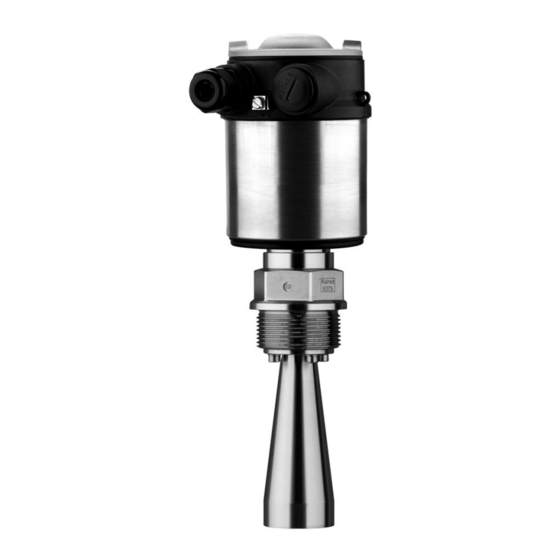
    Prozessanschluss (je nach Ausführung Flansch oder Gewinde) Gehäuse mit Elektronik Gehäusedeckel, optional mit Anzeige- und Bedienmodul Die Komponenten stehen in unterschiedlichen Ausführungen zur Verfügung. Abb. 1: LEVEL TRANSMITTER 8137 - Gewindeausführung mit Kunststoffge- häuse Gehäusedeckel mit darunter liegendem Anzeige- und Bedienmodul (optio- nal) Gehäuse mit Elektronik Prozessanschluss mit Hornantenne LEVEL TRANSMITTER 8137 •...
  • Seite 121: Arbeitsweise

    Artikelnummer Seriennummer Technische Daten Artikelnummern Dokumentation 3.2 Arbeitsweise Der LEVEL TRANSMITTER 8137 ist ein Radarsensor im K-Band Einsatzbereich (Sendefrequenz ca. 26 GHz) zur kontinuierlichen Füllstandmessung. Für den jeweiligen Einsatzbereich steht eine passende Ausführung des LEVEL TRANSMITTER 8137 zur Verfügung. Die Ausführung mit "Gewinde und Hornantenne mit ø 40 mm (1.575 in)"...
  • Seite 122: Bedienung

    PC Mit den herstellerspezifischen Bedienprogrammen AMS™ oder Mit einem HART-Handbediengerät Die eingegebenen Parameter werden generell im LEVEL TRANS- MITTER 8137 gespeichert, optional auch im Anzeige- und Bedien- modul. 3.4 Verpackung, Transport und Lagerung Verpackung Ihr Gerät wurde auf dem Weg zum Einsatzort durch eine Verpackung geschützt.
  • Seite 123: Montieren

    Die Bezugsebene für den Messbereich ist die Flanschunterseite oder die Dichtfläche des Einschraubgewindes. Information: Wenn das Füllgut bis an die Antenne gelangt, können sich langfristig Anhaftungen an der Antenne bilden, die später zu Fehlmessungen führen können. LEVEL TRANSMITTER 8137 • 4 ... 20 mA/HART...
  • Seite 124: Montagevorbereitungen - Hornantenne

    4.2 Montagevorbereitungen - Hornantenne Information: Dieser Hinweis gilt nur für spezielle Ausführungen! Der LEVEL TRANSMITTER 8137 wird auch in Ausführungen geliefert, bei denen die Antenne einen größeren Durchmesser als der Prozessanschluss (Gewinde, Flansch) hat. Vor der Montage muss deshalb die Antenne vom Prozessanschluss demontiert werden.
  • Seite 125: Montagevorbereitungen - Parabolantenne

    4.3 Montagevorbereitungen - Parabolantenne Information: Dieser Hinweis gilt nur für spezielle Ausführungen! Der LEVEL TRANSMITTER 8137 wird auch in Ausführungen geliefert, bei denen die Antenne einen größeren Durchmesser hat als der Prozessanschluss (Gewinde, Flansch). Vor der Montage muss des- halb die Antenne vom Flansch demontiert werden. Gehen Sie wie folgt vor: LEVEL TRANSMITTER 8137 mit dem Flansch festspannen, z.
  • Seite 126: Montagehinweise

    Parabolantenne 4.4 Montagehinweise Horn- und Parabolan- Die Abbildungen zu den folgenden Montagehinweisen stellen einen LEVEL TRANSMITTER 8137 mit Hornantenne dar. Die Montagehin- tenne weise gelten aber sinngemäß auch für die Ausführung mit Parabol- antenne. LEVEL TRANSMITTER 8137 • 4 ... 20 mA/HART...
  • Seite 127 Abb. 6: Montage an runden Behälterdecken Bezugsebene Behältermitte bzw. Symmetrieachse Bei Behältern mit konischem Boden kann es vorteilhaft sein, den Sensor in Behältermitte zu montieren, da die Messung dann bis zum Boden möglich ist. LEVEL TRANSMITTER 8137 • 4 ... 20 mA/HART...
  • Seite 128 Sie sicher, dass Sie die Füllgutoberfläche erfassen und nicht das einströmende Füllgut. Abb. 8: Einströmende Flüssigkeit Stutzen Bevorzugt sollten Sie den Rohrstutzen so dimensionieren, dass der Antennenrand min. 10 mm (0.4 in) aus dem Stutzen herausragt. LEVEL TRANSMITTER 8137 • 4 ... 20 mA/HART...
  • Seite 129 150 mm/6" 800 mm Abb. 10: Abweichende Rohrstutzenmaße Tipp: Optional steht der LEVEL TRANSMITTER 8137 auch mit einer Antennenverlängerung zur Verfügung. Damit kann die Antennenlänge ab Werk so gewählt werden, dass der Antennenrand 10 mm (0.4 in) aus dem Stutzen herausragt Sensorausrichtung Richten Sie den Sensor in Flüssigkeiten möglichst senkrecht auf die...
  • Seite 130 Abb. 12: Glatte Profile mit Streublenden abdecken Rührwerke Bei Rührwerken im Behälter sollten Sie eine Störsignalspeicherung bei laufendem Rührwerk durchführen. Somit ist sichergestellt, dass die Störreflektionen des Rührwerks in unterschiedlichen Positionen ab- gespeichert werden. LEVEL TRANSMITTER 8137 • 4 ... 20 mA/HART...
  • Seite 131 Messung von Füllgütern mit niedrigen Dielekt- rizitätswerten (ab DK-Wert 1,6) möglich. Schwall- oder Bypassrohre müssen bis zur gewünschten minimalen Füllhöhe reichen, da eine Messung nur im Rohr möglich ist. LEVEL TRANSMITTER 8137 • 4 ... 20 mA/HART...
  • Seite 132 Der Antennendurchmesser des Sensors sollte möglichst dem Innen- durchmesser des Rohrs entsprechen. Beim LEVEL TRANSMITTER 8137 sind dies ca. 40 mm (1.575 in). Der Sensor ist bei Rohr- durchmessern von 40 … 80 mm (1.575 … 3.15 in) einsetzbar. Beachten Sie auch die erforderliche obere Entlüftungsbohrung im Schwallrohr, die um 90°...
  • Seite 133 Markierung der Polarisationsrichtung Bei der Montage des Sensors auf einem Bypassrohr sollte der LEVEL TRANSMITTER 8137 ca. 300 mm (11.81 in) oder mehr von der oberen Rohrverbindung entfernt montiert sein. Verwenden Sie bei einer extrem rauen Innenseite des Rohrs ein eingeschobenes Rohr (Rohr im Rohr) oder einen Radarsensor mit Rohrantenne.
  • Seite 134: An Die Spannungsversorgung Anschließen

    Wenn geschirmtes Kabel notwendig ist, legen Sie den Kabelschirm beidseitig auf Erdpotenzial. Im Sensor muss der Schirm direkt an die dung innere Erdungsklemme angeschlossen werden. Die äußere Erdungs- klemme am Gehäuse muss niederimpedant mit dem Potenzialaus- gleich verbunden sein. LEVEL TRANSMITTER 8137 • 4 ... 20 mA/HART...
  • Seite 135: Anschlussschritte

    Ziehen prüfen 10 Schirm an die innere Erdungsklemme anschließen, die äußere Erdungsklemme mit dem Potenzialausgleich verbinden 11 Überwurfmutter der Kabelverschraubung fest anziehen. Der Dichtring muss das Kabel komplett umschließen 12 Gehäusedeckel verschrauben LEVEL TRANSMITTER 8137 • 4 ... 20 mA/HART...
  • Seite 136: Anschlussplan Einkammergehäuse

    5 An die Spannungsversorgung anschließen Der elektrische Anschluss ist somit fertig gestellt. Abb. 16: Anschlussschritte 6 und 7 5.3 Anschlussplan Einkammergehäuse Die nachfolgenden Abbildungen gelten sowohl für die Nicht-Ex-, als auch für die Ex-ia-Ausführung. LEVEL TRANSMITTER 8137 • 4 ... 20 mA/HART...
  • Seite 137: Einschaltphase

    Display I 2 C Abb. 18: Anschlussplan Einkammergehäuse Spannungsversorgung/Signalausgang 5.4 Einschaltphase Nach dem Anschluss des LEVEL TRANSMITTER 8137 an die Einschaltphase Spannungsversorgung bzw. nach Spannungswiederkehr führt das Gerät zunächst ca. 30 Sekunden lang einen Selbsttest durch: Interne Prüfung der Elektronik Anzeige des Gerätetyps, der Firmwareversion sowie des Sensor-...
  • Seite 138: In Betrieb Nehmen Mit Dem Anzeige- Und Bedienmodul

    Anzeige- und Bedienmodul auf die Elektronik setzen und leicht nach rechts bis zum Einrasten drehen Gehäusedeckel mit Sichtfenster fest verschrauben Der Ausbau erfolgt sinngemäß umgekehrt. Das Anzeige- und Bedienmodul wird vom Sensor versorgt, ein weiterer Anschluss ist nicht erforderlich. LEVEL TRANSMITTER 8137 • 4 ... 20 mA/HART...
  • Seite 139 6 In Betrieb nehmen mit dem Anzeige- und Bedienmodul Abb. 19: Einbau des Anzeige- und Bedienmoduls Hinweis: Falls Sie das Gerät mit einem Anzeige- und Bedienmodul zur ständigen Messwertanzeige nachrüsten wollen, ist ein erhöhter Deckel mit Sichtfenster erforderlich. LEVEL TRANSMITTER 8137 • 4 ... 20 mA/HART...
  • Seite 140: Bediensystem

    Die Funktionen der einzelnen Tasten entnehmen Sie bitte der vorhergehenden Darstellung. Ca. 10 Minuten nach der letzten Tastenbetätigung wird ein automatischer Rücksprung in die Messwertanzeige ausgelöst. Dabei gehen die noch nicht mit [OK] bestätigten Werte verloren. LEVEL TRANSMITTER 8137 • 4 ... 20 mA/HART...
  • Seite 141: Inbetriebnahmeschritte

    Hilfe von PACTware bzw. DTM. HART-Betriebsart Standard Adresse 0 Da es sich beim LEVEL TRANSMITTER 8137 um ein Distanzmess- Parametrierung gerät handelt, wird die Entfernung vom Sensor bis zur Füllgutober- fläche gemessen. Um die eigentliche Füllguthöhe anzeigen zu können, muss eine Zuweisung der gemessenen Distanz zur prozentualen Höhe erfolgen.
  • Seite 142 Passend zum Prozentwert den passenden Distanzwert in Meter für den vollen Behälter eingeben. Beachten Sie dabei, dass der maximale Füllstand unterhalb des Totbereiches liegen muss. Speichern der Einstellungen mit [OK] und wechseln mit [->] zur Mediumauswahl. LEVEL TRANSMITTER 8137 • 4 ... 20 mA/HART...
  • Seite 143 Flüssigkeiten eingesetzt. In diesen Fällen ist die Behälterform bei der Inbetriebnahme auf "Lagertank" umzuschalten. Geben Sie die gewünschten Parameter über die entsprechenden Tasten ein, speichern Ihre Eingaben und springen mit der [->]-Taste zum nächsten Menüpunkt. LEVEL TRANSMITTER 8137 • 4 ... 20 mA/HART...
  • Seite 144 Messstellenname oder die Tank- bzw. Produktbezeichnung. In digitalen Systemen und der Dokumen- tation von größeren Anlagen sollte zur genaueren Identifizierung der einzelnen Messstellen eine einmalige Bezeichnung eingegeben werden. Sensor-TAG Sensor LEVEL TRANSMITTER 8137 • 4 ... 20 mA/HART...
  • Seite 145 Bedienmodul. Eine Beschreibung der Funktion finden Sie in der Betriebsanleitung "Anzeige- und Bedienmodul". Folgende Daten werden mit dieser Funktion ausgelesen bzw. ge- schrieben: Messwertdarstellung Abgleich Medium Standrohrinnendurchmesser (bei Standrohrversionen) Behälterform Dämpfung Linearisierungskurve Sensor-TAG LEVEL TRANSMITTER 8137 • 4 ... 20 mA/HART...
  • Seite 146 Stromausgang - Störung Abgleicheinheit m(d) Die Werte folgender Menüpunkte werden mit dem "Reset" nicht auf die Resetwerte (siehe Tabelle) zurückgesetzt: Funktion Resetwert Beleuchtung kein Reset Sprache kein Reset kein Reset HART-Betriebsart kein Reset LEVEL TRANSMITTER 8137 • 4 ... 20 mA/HART...
  • Seite 147 Anzeigeskalierung, Simulation oder Trendkurvendarstellung sind im nachfolgenden Menüplan abgebildet. Eine nähere Beschreibung dieser Menüpunkte finden Sie in der Betriebsanleitung "Anzeige- und Bedienmodul". Spezialparameter sind Parameter, die mit der Bediensoftware PACTware auf der Serviceebene kundenspezifisch eingestellt werden. LEVEL TRANSMITTER 8137 • 4 ... 20 mA/HART...
  • Seite 148: Menüplan

    Linearisierungskurve Sensor-TAG ▼ Sensor linear Display Grundeinstellung ▶ Display Diagnose Service Info Anzeigewert Anzeigeeinheit Skalierung Beleuchtung Skaliert Volumen ▼ Ausgeschaltet ▼ 0 % = 0.0 l ▼ 100 % = 100.0 l LEVEL TRANSMITTER 8137 • 4 ... 20 mA/HART...
  • Seite 149 Sensordaten kopieren? Jetzt aktivieren? Adresse 0 Info Grundeinstellung Display Diagnose Service ▶ Info Gerätetyp Kalibrierdatum letzte Änderung über PC Sensormerkmale 4. August 2008 Softwareversion Jetzt anzeigen? 3.50 4. August 2008 Seriennummer 12345678 LEVEL TRANSMITTER 8137 • 4 ... 20 mA/HART...
  • Seite 150: Sicherung Der Parametrierdaten

    Betriebsanleitung, und anschließend zu archivieren. Sie stehen damit für mehrfache Nutzung bzw. für Servicezwecke zur Verfügung. Ist der LEVEL TRANSMITTER 8137 mit einem Anzeige- und Bedienmodul ausgestattet, so können die wichtigsten Daten aus dem Sensor in das Anzeige- und Bedienmodul gelesen werden. Die Vorgehensweise wird in der Betriebsanleitung "Anzeige- und Bedien-...
  • Seite 151: In Betrieb Nehmen Mit Pactware Und Anderen Bedienprogrammen

    Online-Hilfe von PACTware und den Bürkert- DTMs enthalten. Hinweis: Bitte beachten Sie, dass zur Inbetriebnahme des LEVEL TRANS- MITTER 8137 die DTM-Collection in der aktuellen Version benutzt werden muss. LEVEL TRANSMITTER 8137 • 4 ... 20 mA/HART...
  • Seite 152: Parametrierung Mit Ams™ Und Pdm

    Sie stehen damit für mehrfache Nutzung bzw. für Service- zwecke zur Verfügung. Die Bürkert-DTM-Collection und PACTware in der lizenzierten, professionellen Version bieten Ihnen die geeigneten Werkzeuge für eine systematische Projektspeicherung und -dokumentation. LEVEL TRANSMITTER 8137 • 4 ... 20 mA/HART...
  • Seite 153: Instandhalten Und Störungen Beseitigen

    à Leitungen auf Unterbrechung prüfen, ggf. reparieren Betriebsspannung zu niedrig bzw. Bürdenwiderstand zu hoch à Prüfen, ggf. anpassen Stromsignal größer 22 mA oder kleiner 3,6 mA Elektronikeinsatz defekt à Gerät austauschen bzw. zur Reparatur einsenden LEVEL TRANSMITTER 8137 • 4 ... 20 mA/HART...
  • Seite 154 Hardwarefehler, Elektronik defekt à Gerät austauschen bzw. zur Reparatur einsenden Verhalten nach Stö- Je nach Störungsursache und getroffenen Maßnahmen sind ggf. die rungsbeseitigung im Kapitel "In Betrieb nehmen" beschriebenen Handlungsschritte erneut zu durchlaufen. LEVEL TRANSMITTER 8137 • 4 ... 20 mA/HART...
  • Seite 155: Ausbauen

    Mensch und Umwelt und ermöglicht eine Wiederverwendung von wertvollen Rohstoffen. Werkstoffe: siehe Kapitel "Technische Daten" Sollten Sie keine Möglichkeit haben, das Altgerät fachgerecht zu entsorgen, so sprechen Sie mit uns über Rücknahme und Entsorgung. LEVEL TRANSMITTER 8137 • 4 ... 20 mA/HART...
  • Seite 156: Anhang

    HART-Wert (Primary Value) Distanz zum Füllstand HART-Wert (Secondary Value) Distanz zum Füllstand - skaliert 1,6 µA Signalauflösung mA-Wert unverändert 20,5 mA, 22 mA, < 3,6 mA Ausfallsignal Stromausgang (einstellbar) (einstellbar) 22 mA Max. Ausgangsstrom LEVEL TRANSMITTER 8137 • 4 ... 20 mA/HART...
  • Seite 157 < 1 s (abhängig von der Parametrierung) Sprungantwort- oder Einstellzeit Einstellbar bis 1 m/min. (abhängig von der Para- Max. Füllstandänderung metrierung) Zeit bis zur richtigen Ausgabe (max. 10 % Abweichung) des Füllstandes bei einer sprunghaften Füllstandänderung. LEVEL TRANSMITTER 8137 • 4 ... 20 mA/HART...
  • Seite 158 Diagramme 10 mm 3 mm 0,5 m 30 m -3 mm -10 mm Abb. 22: Messabweichung LEVEL TRANSMITTER 8137 mit Hornantenne in mm, Messbereich in m Inkl. Nichtlinearität, Hysterese und Nichtwiederholbarkeit. LEVEL TRANSMITTER 8137 • 4 ... 20 mA/HART...
  • Seite 159 40 mm 3 mm -3 mm 2,0 m 30 m -40 mm Abb. 23: Messabweichung LEVEL TRANSMITTER 8137 mit Parabolantenne in mm, Messbereich in m Einfluss der Umgebungstemperatur auf die Sensorelektronik 0,03 %/10 K Mittlerer Temperaturkoeffizient des Nullsig- nals (Temperaturfehler) Umgebungsbedingungen Umgebungs-, Lager- und Transporttempera- -40 …...
  • Seite 160 20 … 36 V DC EEx-d-ia-Gerät Zulässige Restwelligkeit < 100 Hz < 1 V 100 Hz … 10 kHz < 10 mV Bürde siehe Diagramm Geprüft nach den Richtlinien des Germanischen Lloyd, GL-Kennlinie 2. LEVEL TRANSMITTER 8137 • 4 ... 20 mA/HART...
  • Seite 161 ATEX II 1G, 1/2G, 2G EEx ia IIC T5+ATEX II 1/2D ATEX ia + D IP6X T6 IEC ia IEC Ex ia IIC T6 Sonstige Abweichende Daten bei Ex-Anwendungen: siehe separate Sicherheitshin- weise. Je nach Bestellspezifikation. LEVEL TRANSMITTER 8137 • 4 ... 20 mA/HART...
  • Seite 162: Maße

    10 Anhang 10.2 Maße Gehäuse ~ 76 mm ") ø 91 mm ") M20x1,5/ ½ NPT Abb. 25: Gehäuse LEVEL TRANSMITTER 8137 • 4 ... 20 mA/HART...
  • Seite 163 ø75 4" ø95 inch " ø1 " 1½" " ø1 " 2" " ø2 " 3" " ø3 " 4" Abb. 26: LEVEL TRANSMITTER 8137 - Hornantenne in Gewindeausführung Standard Mit Temperaturzwischenstück LEVEL TRANSMITTER 8137 • 4 ... 20 mA/HART...
  • Seite 164 4" 150 lb " " " 6" 150 lb 279,4 25,4 241,3 8xø22,4 6" 150 lb 11" 1" " 8xø " " Abb. 27: LEVEL TRANSMITTER 8137 - Hornantenne in Flanschausführung Standard Mit Temperaturzwischenstück LEVEL TRANSMITTER 8137 • 4 ... 20 mA/HART...
  • Seite 165 10 Anhang LEVEL TRANSMITTER 8137 - Parabolantenne in Gewindeausführung 46mm ") G1½A / 1½ NPT ø 244mm (9 ") Abb. 28: LEVEL TRANSMITTER 8137 - Parabolantenne in Gewindeausführung Standard Mit Temperaturzwischenstück LEVEL TRANSMITTER 8137 • 4 ... 20 mA/HART...
  • Seite 166 190,5 8xø19,1 4" 150 lb 11" 1" " 8xø " 6" 150 lb 279,4 25,4 241,3 8xø22,4 6" 150 lb Abb. 29: LEVEL TRANSMITTER 8137 - Parabolantenne in Flanschausführung Standard Mit Temperaturzwischenstück LEVEL TRANSMITTER 8137 • 4 ... 20 mA/HART...
  • Seite 167 10 Anhang LEVEL TRANSMITTER 8137 • 4 ... 20 mA/HART...
  • Seite 168 The smart choice of Fluid Control Systems www.buerkert.com Technische Änderungen vorbehalten 32065-DE-081114...

Inhaltsverzeichnis