Herunterladen Inhalt Inhalt Diese Seite drucken
Endress+Hauser EngyCal RH33 Handbuch

Endress+Hauser EngyCal RH33 Handbuch

Btu meter
Vorschau ausblenden Andere Handbücher für EngyCal RH33:
Inhaltsverzeichnis

Werbung

Verfügbare Sprachen

Verfügbare Sprachen

Brief operating instructions
®
EngyCal
RH33
BTU meter
KA289K/09/c3/07.10
71110029

Werbung

Inhaltsverzeichnis
loading

Inhaltszusammenfassung für Endress+Hauser EngyCal RH33

  • Seite 1 Brief operating instructions ® EngyCal RH33 BTU meter KA289K/09/c3/07.10 71110029...
  • Seite 2: Inhaltsverzeichnis

    Ausführliche Informationen entnehmen Sie bitte der Betriebsanleitung und der weiteren Doku- mentation auf der mitgelieferten CD-ROM. Diese Kurzanleitung ersetzt nicht die Betriebsanleitung. Die komplette Gerätedokumentation besteht aus: • der vorliegenden Kurzanleitung • einer CD-ROM mit: – der Betriebsanleitung – Zulassungen und Sicherheitszertifikaten – weiteren gerätespezifischen Informationen. Endress+Hauser...
  • Seite 3: Sicherheitshinweise

    Der Wärmezähler darf nur im eingebauten Zustand betrieben werden. Betriebssicherheit Technischer Fortschritt Der Hersteller behält sich vor, technische Details ohne spezielle Ankündigung dem entwick- lungstechnischen Fortschritt anzupassen. Über die Aktualität und eventuelle Erweiterungen der Betriebsanleitung erhalten Sie bei Ihrer Vertriebsstelle Auskunft. Endress+Hauser...
  • Seite 4: Rücksendung

    - zur Verletzung von Personen, zu einem Sicherheitsrisiko oder zur Zer- störung des Gerätes führen können. Hinweis! Dieses Symbol deutet auf Aktivitäten oder Vorgänge hin, die - wenn sie nicht ordnungsgemäß durchgeführt werden - einen indirekten Einfluss auf den Betrieb haben oder eine unvorherge- sehene Gerätereaktion auslösen können. Endress+Hauser...
  • Seite 5: Identifizierung

    Bestellcode und Seriennummer Versorgungsspannung Leistungsaufnahme Firmware Version Zulassungen, falls vorhanden Angaben zu Temperatursensoren Umgebungstemperaturbereich Device Revision Schutzart Herstellungsort und -jahr 2.1.2 Frontfolie bei Geräten mit Eichzulassung Bei Geräten mit der Option Eichzulassung wird die Frontfolie mit folgenden Informationen bedruckt: Endress+Hauser...
  • Seite 6: Lieferumfang

    • Optional Schnittstellenkabel und DVD Set mit Parametriersoftware FieldCare Device Setup • Optional Field Data Manager software • Optional Befestigungsmaterial für Hutschiene, Schalttafel, Rohrmontage • Optional Überspannungsschutz Hinweis! Beachten Sie im Kap. 8 ’Zubehör’ in der Betriebsanleitung auf CD-ROM die Zubehörteile des Gerätes. Endress+Hauser...
  • Seite 7: Zertifikate Und Zulassungen

    Normen und Vorschriften nach EN 61 010 "Sicherheitsbestimmungen für elektrische Mess-, Steuer, Regel- und Laborgeräte". Das in dieser Betriebsanleitung beschriebene Gerät erfüllt somit die gesetzlichen Anforderungen der EU-Richtlinien. Der Hersteller bestätigt die erfolgreiche Prüfung des Gerätes mit der Anbrin- gung des CE-Zeichens. Endress+Hauser...
  • Seite 8: Montage

    • Für Lagerung (und Transport) ist das Gerät stoßsicher zu verpacken. Dafür bietet die Origi- nalverpackung optimalen Schutz. • Die zulässige Lagerungstemperatur beträgt -40 bis +85°C (-40 bis +185 °F); die Lagerung in den Grenztemperaturbereichen ist zeitlich begrenzt (maximal 48 Stunden). Endress+Hauser...
  • Seite 9: Abmessungen

    EngyCal® RH33 Montage Abmessungen a0013438 Abb. 3: Abmessungen des Geräts Endress+Hauser...
  • Seite 10: Einbaubedingungen

    Displays. Montage 3.4.1 Wandmontage Montageplatte als Schablone für Bohrungen verwenden, Abmessungen → å 4 a0014169 Abb. 4: Montage-Platte für Wandmontage Wärmezähler auf Montageplatte aufsetzen und mit 4 Schrauben von hinten fixieren. Montageplatte mit 4 Schrauben an der Wand befestigen. Endress+Hauser...
  • Seite 11 EngyCal® RH33 Montage a0014170 Abb. 5: Wandmontage 3.4.2 Schalttafeleinbau Schalttafelausschnitt in der erforderlichen Größe herstellen, Abmessungen → å 6. a0014171 Abb. 6: Schalttafelausschnitt Endress+Hauser...
  • Seite 12 Gewindestangen (Pos. 2) in Montageplatte einschrauben. a0014173 Abb. 8: Montageplatte für Schalttafel-Montage vorbereiten Gerät von vorn in Schalttafelausschnitt schieben und Montageplatte von hinten mit den 4 mitgelieferten Schrauben (Pos. 3) am Gerät anbringen. Gerät durch Festziehen der Gewindestangen fixieren. Endress+Hauser...
  • Seite 13 EngyCal® RH33 Montage a0014174 Abb. 9: Schalttafel-Montage 3.4.3 Tragschiene/Hutschiene (nach EN 50 022) Hutschienenadapter (Pos. 1) mit den mitgelieferten Schrauben (Pos. 2) am Gerät befesti- gen und die Hutschienen-Clips öffnen. Endress+Hauser...
  • Seite 14 Montage EngyCal® RH33 a0014176 Abb. 10: Hutschienenmontage vorbereiten Gerät von vorn auf Hutschiene aufsetzen und Hutschienen-Clips schließen. a0014177 Abb. 11: Hutschienenmontage Endress+Hauser...
  • Seite 15 EngyCal® RH33 Montage 3.4.4 Rohrmontage Stahlbänder durch Montageplatte ziehen und am Rohr befestigen. a0014178 Abb. 12: Rohrmontage vorbereiten Gerät auf Montageplatte aufsetzen und mit den 4 beigelegten Schrauben befestigen. a0014179 Abb. 13: Rohrmontage Endress+Hauser...
  • Seite 16: Einbauhinweise Temperatursensoren

    Schutzrohres weit genug in den Prozess ragt, um über die Achse der Rohrleitung hinaus zu rei- chen (→ å 14, Pos. A und B). Eine andere Lösung kann ein schräger Einbau sein (→ å 14, Pos. C und D). Bei der Bestimmung der Eintauchlänge bzw. Einbautiefe müssen alle Parameter Endress+Hauser...
  • Seite 17: Einbaukontrolle

    Thermometers und des zu messenden Prozesses berücksichtigt werden (z. B. Durchflussge- schwindigkeit, Prozessdruck). Siehe auch Einbauempfehlungen EN1434-2 ( D) Bild 8. Einbaukontrolle Hinweis! Für die Installation des Wärmezählers und der zugehörigen Temperatursensoren sind die allge- meinen Einbauvorschriften gem. EN 1434 Teil 6 zu beachten. Endress+Hauser...
  • Seite 18: Verdrahtung

    • Für die Netzleitung ist ein Überstromschutzorgan (Nennstrom = 10 A) erforderlich. Für den Einbau des Wärmezählers und der zugehörigen Teilgeräte sind die allgemeinen Vor- schriften gem. EN1434-Teil 6 zu beachten. Verdrahtung auf einen Blick a0013439 Abb. 15: Anschlussbild des Wärmezählers Endress+Hauser...
  • Seite 19: Klemmenbelegung

    Ausgänge + Impuls-Ausgang 1 (Open Collector) Energie-, Volumen- oder Tarifzähler. Alterna- tiv Grenzwerte/Alarme - Impuls-Ausgang 1 (Open Collector) + Impuls-Ausgang 2 (Open Collector) - Impuls-Ausgang 2 (Open Collector) + 0/4…20mA/Impuls-Ausgang Momentanwerte (z.B. Leistung) oder Zähler- werte (z.B. Energie) 0/4…20mA/Impuls-Ausgang Endress+Hauser...
  • Seite 20: Gehäuse Öffnen

    Relais 2 Schließer (Normally Open) 24V Sensorversorgung (LPS) 24 V Versorgung (z.B. für Sensorspeisung) Masse Versorgung Netzversorgung L für AC + für DC N für AC - für DC 4.2.1 Gehäuse öffnen a0014071 Abb. 16: Gehäuse des Wärmezählers öffnen Beschriftung Klemmenbelegung Anschlussklemmen Endress+Hauser...
  • Seite 21: Anschluss Der Sensoren

    Abb. 17: Anschluss eines Durchfluss-Sensors Spannungsimpulse einschließlich EN 1434 Typ IB, IC, ID, IE Stromimpulse 0/4…20 mA Signal (nicht in Kombination mit Option MID Zulassung) Durchflusssensoren mit Versorgung über den Wärmezähler a0014180 Abb. 18: Anschluss aktiver Durchflusssensoren 4-Leiter-Sensor 2-Leiter-Sensor Endress+Hauser...
  • Seite 22 Verdrahtung EngyCal® RH33 Endress+Hauser Durchflussmessgeräte Durchflusssensoren mit PFM- oder Impulsausgang: Proline Prowirl 72 und Pro- line Prosonic Flow 92F a0014181 1 = PFM, 2 = Impuls: Klemmen 90/91 Messumformerspeisung, alternativ über externes Speisegerät Durchflusssensoren mit Strom- oder Impulsausgang: Proline Promag 10W...
  • Seite 23: Endress+Hauser Temperatursensoren Und -Transmitter

    Klemmen 54, 55: T kalt Hinweis! Zur Gewährleistung höchster Genauigkeiten ist die Verwendung des RTD 4-Leiteranschluss empfohlen, da hierdurch Messungenauigkeiten durch Einbauort der Fühler oder Leitungslänge der Anschlusskabel kompensiert werden. Endress+Hauser Temperatursensoren und -transmitter Anschluss TR10 RTD-Sensor a0014187 Anschluss TMT181, TMT121 Temperaturtrans-...
  • Seite 24: Ausgänge

    Kabel durch das Gehäuse zu führen. Über die Ethernet-Schnittstelle kann das Gerät mit einem Hub, Switch oder direkt mit Geräten in Büroumgebung verbunden werden. Für die Sicherheits- abstände muss die Bürogerätenorm EN 60950 berücksichtigt werden. • Standard: 10/100 Base-T/TX (IEEE 802.3) • Buchse: RJ-45 • Max. Leitungslänge: 100 m Endress+Hauser...
  • Seite 25: Anschlusskontrolle

    Sind Gerät oder Kabel beschädigt (Sichtkontrolle)? Elektrischer Anschluss Hinweise Stimmt die Versorgungsspannung mit den Angaben auf dem Typenschild 100 bis 230 V AC/DC (±10%) überein? (50/60 Hz) Sind die montierten Kabel von Zug entlastet? Sind Hilfsenergie- und Signalkabel korrekt angeschlossen? siehe Anschlussschema am Gehäuse Endress+Hauser...
  • Seite 26: Bedienung

    Gerät versorgt wird. Langsames blinken der roten LED (ca. 0,5 Hz): Das Gerät wurde in den Bootloadermodus gesetzt. Schnelles Blinken der roten LED (ca. 2 Hz): Im Normalbetrieb: Wartungsbedarf. Während Firm- ware-Update: Datenübertragung aktiv. Dauerndes Leuchten der roten LED: Gerätefehler. Endress+Hauser...
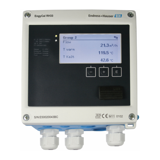
  • Seite 27: Bedienelemente

    Funktion Enter / Eingabe bestätigen: "E" drücken 5.2.2 Anzeige a0013462 Abb. 20: Anzeige des Wärmezählers (beispielhaft) Anzeige Gruppe 1 Anzeige Gruppe 2, Wartung erforderlich, Setup verriegelt, oberer Grenzwert Flow verletzt Hinweis! Eine Liste der Anzeigesymbole finden Sie im Anhang der Betriebsanleitung auf CD-ROM. Endress+Hauser...
  • Seite 28 Das gesamte Setup-Menü, also alle in dieser Betriebsanleitung aufgeführten Para- meter finden Sie ebenfalls in FieldCare Device Setup vor. Hinweis! Während der Parametrierung mit FieldCare kann das Gerät undefinierte Zustände annehmen! Dies kann das undefinierte Schalten von Ausgängen und Relais zur Folge haben. Endress+Hauser...
  • Seite 29: Bedienmatrix

    Das Expertenmenü bietet Zugriff auf auf alle Bedienpositionen des Geräts, inklusive Feintuning und Servicefunktionen. • Direktsprung in Parameter über Direct Access (nur am Gerät) • Servicecode zur Anzeige von Serviceparametern (nur über PC-Bediensoftware) • System(-einstellungen) • Eingänge • Ausgänge • Applikation • Diagnose Endress+Hauser...
  • Seite 30: Schnellinbetriebnahme/Make It Run

    Das Gerät ist nun betriebsbereit für die Erfassung der Wärmeenergie (Kälteenergie). Die Einstellung der Gerätefunktionalitäten, wie z.B. Datenlogging, Tariffunktion, Busanbindung sowie die Skalierung von Stromeingängen für Durchfluss oder Temperatur erfolgt im Menü „Erweitertes Setup“. Detaillierte Informationen zur Gerätekonfiguration finden Sie in der Betriebsanleitung auf der mitgelieferten CD-ROM. Endress+Hauser...
  • Seite 31 CD-ROM provided. These Brief Operating Instructions do not replace the Operating Instructions. The complete device documentation consists of: • These Brief Operating Instructions • A CD-ROM with: – The Operating Instructions – Approvals and safety certificates – Other device-specific information Endress+Hauser...
  • Seite 32: Safety Instructions

    The BTU meter may be operated in built-in state only. Operational safety Technical improvement The manufacturer reserves the right to improve and update the technical details. For details of improvements or additions to these instructions, please contact your local sales organization. Endress+Hauser...
  • Seite 33: Return

    Note! This symbol draws attention to activities or procedures that have an indirect effect on operation, or can trigger an unforeseen device reaction if not carried out properly. Endress+Hauser...
  • Seite 34: Identification

    Device revision Degree of protection Place and year of manufacture 2.1.2 Front foil for devices with approval for custody transfer For devices with the option of approval for custody transfer, the front foil is imprinted with the following information: Endress+Hauser...
  • Seite 35: Scope Of Delivery

    • Optional interface cable and DVD set with FieldCare Device Setup parameter configuration software • Optional Field Data Manager software • Optional mounting hardware for top-hat rail, panel mounting, pipe mounting • Optional overvoltage protection Note! Please note the device accessories in Section 8 ’Accessories’ in the Operating Instructions on CD-ROM. Endress+Hauser...
  • Seite 36: Certificates And Approvals

    EN 61 010 "Safety requirements for electrical equipment for measurement, control and laboratory use". Thus, the device described in these Operating Instructions meets the legal requirements of the EU Directives. The manufacturer confirms successful testing of the device by affixing to it the CE mark. Endress+Hauser...
  • Seite 37: Installation

    • Pack the device in such a way as to protect it reliably against impact for storage (and transportation). The original packaging provides optimum protection. • The permitted storage temperature range is -40 to +85°C (-40 to +185 °F); storage in the temperature limit ranges is possible for a limited time only (maximum of 48 hours). Endress+Hauser...
  • Seite 38: Dimensions

    Installation EngyCal® RH33 Dimensions a0013438 Fig. 3: Dimensions of the device Endress+Hauser...
  • Seite 39: Installation

    Use the mounting plate as the template for drilled holes, dimensions → å 4 a0014169 Fig. 4: Mounting plate for wall mounting Attach the BTU meter to the mounting plate and fasten it in place from the rear using 4 screws. Fasten the mounting plate to the wall using 4 screws. Endress+Hauser...
  • Seite 40: Panel Mounting

    Installation EngyCal® RH33 a0014170 Fig. 5: Wall mounting 3.4.2 Panel mounting Make the panel cutout in the required size, dimensions → å 6. a0014171 Fig. 6: Panel cutout Endress+Hauser...
  • Seite 41 Fig. 8: Preparing the mounting plate for panel mounting Push the device into the panel cutout from the front and attach the mounting plate to the device from the rear using the 4 screws provided (item 3). Fasten the device in place by tightening the threaded rods. Endress+Hauser...
  • Seite 42 Installation EngyCal® RH33 a0014174 Fig. 9: Panel mounting 3.4.3 Support rail/top-hat rail (to EN 50 022) Fasten the top-hat rail adapter (item 1) to the device using the screws provided (item 2) and open the top-hat rail clips. Endress+Hauser...
  • Seite 43 EngyCal® RH33 Installation a0014176 Fig. 10: Preparing for top-hat rail mounting Attach the device to the top-hat rail from the front and close the top-hat rail clips. a0014177 Fig. 11: Top-hat rail mounting Endress+Hauser...
  • Seite 44 Pull the steel belts through the mounting plate and fasten them to the pipe. a0014178 Fig. 12: Preparing for pipe mounting Attach the device to the mounting plate and fasten it in place using the 4 screws provided. a0014179 Fig. 13: Pipe mounting Endress+Hauser...
  • Seite 45: Installation Instructions For Temperature Sensors

    For pipes with small nominal diameters, ensure that the tip of the thermowell extends far enough into the process so that it also protrudes past the axis of the pipe (→ å 14, item A and B). Another solution may be diagonal installation (→ å 14, item C and D). To determine the Endress+Hauser...
  • Seite 46: Post-Installation Check

    (e.g. flow velocity, process pressure). Refer also to the installation recommendations EN1434-2 ( D), Figure 8. Post-installation check Note! For installing the BTU meter and the associated temperature sensors, observe the general installation instructions according to EN 1434 Part 6. Endress+Hauser...
  • Seite 47: Wiring

    • An overload protection unit (rated current = 10 A) is required for the power cable. For installing the BTU meter and the associated components, observe the general instructions according to EN 1434 Part 6. Quick wiring guide a0013439 Fig. 15: Connection diagram of the BTU meter Endress+Hauser...
  • Seite 48: Terminal Assignment

    Energy, volume or tariff counter. Alternative: limits/alarms - pulse output 1 (open collector) + pulse output 2 (open collector) - pulse output 2 (open collector) + 0/4 to 20mA/pulse output Current values (e.g. power) or counter values (e.g. energy) 0/4 to 20mA/pulse output Endress+Hauser...
  • Seite 49 (e.g. for sensor power supply) Power supply ground Power supply L for AC + for DC N for AC - for DC 4.2.1 Open housing a0014071 Fig. 16: Opening the housing of the BTU meter Terminal assignment labeling Terminals Endress+Hauser...
  • Seite 50: Connecting The Sensors

    Voltage pulses including EN 1434 Type IB, IC, ID, IE Current pulses 0/4 to 20 mA signal (not in combination with MID approval option) Flow sensors with power supply via the BTU meter a0014180 Fig. 18: Connecting active flow sensors 4-wire sensor 2-wire sensor Endress+Hauser...
  • Seite 51 EngyCal® RH33 Wiring Endress+Hauser flowmeters Flow sensors with PFM or pulse output: Proline Prowirl 72 and Proline Prosonic Flow 92F a0014181 1 = PFM, 2 = Pulse: terminals 90/91 transmitter power supply, alternatively via external supply unit Flow sensors with current or...
  • Seite 52 To ensure the highest level of accuracy, we recommend using the RTD 4-wire connection, as this compensates for measurement inaccuracies caused by the mounting location of the sensors or the line length of the connecting cables. Endress+Hauser temperature sensors and transmitters Connection for TR10 RTD sensor...
  • Seite 53: Outputs

    Ethernet interface, the device can be connected using a hub or a switch or directly to office equipment. Office Equipment Standard EN 60950 must be taken into consideration to ensure correct safety distances. • Standard: 10/100 Base-T/TX (IEEE 802.3) • Socket: RJ-45 • Max. line length: 100 m Endress+Hauser...
  • Seite 54: Post-Connection Check

    Does the supply voltage match the information on the nameplate? 100 to 230 V AC/DC (±10%) (50/60 Hz) Are the mounted cables relieved of tension? Are the power supply and signal cables connected correctly? See wiring diagram on the housing Endress+Hauser...
  • Seite 55: Operation

    Slow flashing of the red LED (approx. 0.5 Hz): the device has been put into bootloader mode. Fast flashing of the red LED (approx. 2 Hz): in normal operation: maintenance required. During firmware update: data transmission active. Red LED illuminated constantly: device error. Endress+Hauser...
  • Seite 56: Operating Elements

    USB interface. Establishing a connection Proceed as follows: Start FieldCare. Connect the device to the computer via USB. Generate project via File/New. Select communication DTM (CDI Communication USB). ® Add EngyCal RH33 or RS33. Click "Establish connection". Start online configuration. Endress+Hauser...
  • Seite 57 The entire Setup menu, i.e. all parameters listed in these Operating Instructions, is also included in the FieldCare Device Setup. Note! During configuration with FieldCare, the device can enter undefined states! This can result in undefined switching of outputs and relays. Endress+Hauser...
  • Seite 58: Operating Matrix

    • Service code for displaying service parameters (via PC operating software only) • System (settings) • Inputs • Outputs • Application • Diagnostics Quick commissioning/make it run For quick commissioning of the "standard" BTU meter application, you only have to enter 4 operating parameters in the menu Setup. Endress+Hauser...
  • Seite 59 You can configure device functions, such as data logging, tariff function, bus connection and the scaling of current inputs for flow or temperature, in the "Advanced setup" menu. For detailed information about the device configuration, refer to the Operating Instructions on the CD-ROM provided. Endress+Hauser...
  • Seite 60 Queste Istruzioni di funzionamento brevi non sostituiscono le Istruzioni di funzionamento. La documentazione completa dello strumento comprende: • Queste Istruzioni di funzionamento brevi • Un CD-ROM con: – Istruzioni di funzionamento – Approvazioni e certificati di sicurezza – Altre informazioni specifiche sul dispositivo. Endress+Hauser...
  • Seite 61: Istruzioni Di Sicurezza

    Il computer per il calcolo dell'energia termica può essere impiegato solo se correttamente installato. Sicurezza operativa Migliorie tecniche Il produttore si riserva il diritto di aggiornare le specifiche tecniche. Per altre informazioni su aggiornamenti o integrazioni delle presenti istruzioni, rivolgersi all'Ufficio Vendite locale. Endress+Hauser...
  • Seite 62: Spedizione In Fabbrica

    Nota! Questo simbolo indica attività o procedure che, se non eseguite correttamente, possono avere un effetto indiretto sul funzionamento o possono causare una risposta inattesa dello strumento. Endress+Hauser...
  • Seite 63: Identificazione

    Revisione del dispositivo Classe di protezione Luogo e anno di fabbricazione 2.1.2 Identificativo sul lato anteriore dei dispositivi approvati per uso fiscale In caso di approvazione per misura fiscale, sul lato anteriore dei dispositivi sono stampate le seguenti informazioni: Endress+Hauser...
  • Seite 64: Fornitura

    • software Field Data Manager, opzionale • componenti per montaggio su guida top-hat, a fronte quadro o su palina, opzionali • protezione alle sovratensioni, opzionale Nota! Consultare l'elenco degli accessori, riportato nel capitolo 8 "Accessori" delle Istruzioni di funzionamento. Endress+Hauser...
  • Seite 65: Certificati E Approvazioni

    Pertanto, il dispositivo descritto in queste istruzioni di funzionamento possiede i requisiti previsti dalle direttive EU. Il produttore dichiara che il computer per il calcolo dell'energia termica ha superato con successo il collaudo apponendovi il marchio CE. Endress+Hauser...
  • Seite 66: Installazione

    L'imballaggio originale rappresenta una protezione ottimale. • La temperatura di immagazzinamento deve essere compresa tra -40 e +85°C; il dispositivo deve essere conservato a temperature prossime ai valori soglia solo per breve tempo (massimo 48 ore), se possibile. Endress+Hauser...
  • Seite 67: Dimensioni

    Installazione EngyCal® RH33 Dimensioni a0013438 Fig. 3: Dimensioni del dispositivo Endress+Hauser...
  • Seite 68: Installazione

    Per l'esecuzione dei fori utilizzare la piastra di montaggio come dima, dimensioni → å 4 a0014169 Fig. 4: Piastra per montaggio a muro Sistemare il computer per il calcolo dell'energia termica sulla piastra di montaggio e bloccarlo dal lato posteriore con 4 viti. Fissare la piastra di montaggio alla parete mediante 4 viti. Endress+Hauser...
  • Seite 69 Installazione EngyCal® RH33 a0014170 Fig. 5: Montaggio a muro 3.4.2 Montaggio a fronte quadro Eseguire la foratura del quadro in base alle dimensioni → å 6. a0014171 Fig. 6: Dima di foratura Endress+Hauser...
  • Seite 70 Fig. 8: Preparazione della piastra per montaggio a fronte quadro Spingere il dispositivo sostenendolo dal lato anteriore nell'apertura eseguita nel quadro e fissare la piastra di montaggio sul lato posteriore del dispositivo con le 4 viti fornite (pos. 3). Bloccare il dispositivo in sede serrando le aste filettate. Endress+Hauser...
  • Seite 71 Fig. 9: Montaggio a fronte quadro 3.4.3 Guida di supporto/guida top-hat (secondo EN 50 022) Fissare l'adattatore della guida top-hat (pos. 1) al dispositivo utilizzando le viti fornite (pos. 2) e aprire gli elementi di fissaggio della guida top-hat. Endress+Hauser...
  • Seite 72 EngyCal® RH33 Installazione a0014176 Fig. 10: Preparazione del montaggio su guida top-hat Montare il dispositivo sulla guida top-hat sostenendolo dal lato anteriore e chiudere gli elementi di fissaggio della guida top-hat. a0014177 Fig. 11: Montaggio su guida top-hat Endress+Hauser...
  • Seite 73 Inserire le fascette di ferro attraverso la piastra di montaggio e fissarle alla palina. a0014178 Fig. 12: Preparazione del montaggio su palina Appoggiare il dispositivo sulla piastra di montaggio e fissarlo in sede con le 4 viti. a0014179 Fig. 13: Montaggio su palina Endress+Hauser...
  • Seite 74: Istruzioni Di Installazione Per I Sensori Di Temperatura

    (→ å 14, pos. A e B). Una soluzione alternativa è l'installazione in diagonale (→ å 14, pos. C e D). Per determinare la lunghezza di immersione o la profondità di installazione, si devono considerare Endress+Hauser...
  • Seite 75: Verifica Finale Dell'installazione

    Per l'installazione, consultare anche la normativa per l'installazione EN1434-2 ( D), figura 8. Verifica finale dell'installazione Nota! Per installare il computer per il calcolo dell'energia termica e i sensori di temperatura associati, rispettare le istruzioni di installazione generali secondo EN 1434 Parte 6. Endress+Hauser...
  • Seite 76: Cablaggio

    Per installare il computer per il calcolo dell'energia termica e i componenti associati, rispettare le istruzioni di installazione generali secondo EN 1434 Parte 6. Guida rapida al cablaggio a0013439 Fig. 15: Schema di connessione del computer per il calcolo dell'energia termica Endress+Hauser...
  • Seite 77: Assegnazione Dei Morsetti

    - uscita impulsi 1 (open collector) + uscita impulsi 2 (open collector) - uscita impulsi 2 (open collector) + 0/4...20 mA/uscita impulsi Valori corrente (ad es. potenza) o valori del contatore (ad es. energia) 0/4...20 mA/uscita impulsi Endress+Hauser...
  • Seite 78: Apertura Della Custodia

    Terra per alimentazione Alimentazione L per c.a. + per c.c. N per c.a. - per c.c. 4.2.1 Apertura della custodia a0014071 Fig. 16: Apertura della custodia del computer per il calcolo dell'energia termica Etichettatura con l'assegnazione dei morsetti Morsetti Endress+Hauser...
  • Seite 79: Connessione Dei Sensori

    Segnale 0/4...20 mA (non in combinazione con l'opzione di approvazione MID) Sensori di portata alimentati mediante il computer per il calcolo dell'energia termica a0014180 Fig. 18: Connessione dei sensori di portata attivi Sensore a 4 fili Sensore a 2 fili Endress+Hauser...
  • Seite 80 EngyCal® RH33 Cablaggio Misuratori di portata Endress+Hauser Sensori di portata con uscita EngyCal RH33 Prowirl 72 PFM o impulsi: Proline Prowirl 72 e Proline Prosonic Flow 92F Prosonic Flow 92F a0014181 1 = PFM, 2 = impulsi: morsetti 90/91 per l'alimentazione trasmettitore, in alternativa...
  • Seite 81 Per ottenere la massima accuratezza, si consiglia di utilizzare la connessione RTD a 4 fili, poiché consente di compensare l'inaccuratezza delle misure dovuta al punto di installazione dei sensori o alla lunghezza della linea dei cavi di collegamento. Sensori e trasmettitori di temperatura Endress+Hauser Connessione per il sensore RTD TR10...
  • Seite 82: Uscite

    In questo caso, per garantire le corrette distanze di sicurezza, rispettare lo standard EN 60950. • Standard: 10/100 Base-T/TX (IEEE 802.3) • Ingresso: RJ-45 • Lunghezza della linea max.: 100 m Endress+Hauser...
  • Seite 83: Verifica Finale Delle Connessioni

    La tensione di alimentazione corrisponde a quanto indicato sulla targhetta? 100...230 V c.a./c.c. (±10%) (50/60 Hz) I cavi sono stesi in modo da non essere sottoposti a trazione? L’alimentazione e i cavi di segnale sono collegati correttamente? vedere schema elettrico sulla custodia Endress+Hauser...
  • Seite 84: Funzionamento

    Display a matrice di punti 160x80 Nota! LED verde per tensione, LED rosso per allarme/errore. Il LED verde è sempre accesso, se il dispositivo è alimentato. Il LED rosso lampeggia lentamente (0,5 H ca.): il dispositivo è stato impostato in modalità bootloader. Endress+Hauser...
  • Seite 85: Elementi Operativi

    USB del PC. Stabilire una connessione Procedere come indicato di seguito: Avviare FieldCare. Collegare il dispositivo al PC mediante USB. Creare un progetto mediante File/Nuovo. Selezionare il DTM di comunicazione (CDI Communication USB). ® Aggiungere il dispositivo EngyCal RH33 o RS33. Endress+Hauser...
  • Seite 86 Il menu Setup completo, ossia tutti i parametri elencati in queste Istruzioni di funzionamento, è compreso anche in FieldCare Device Setup. Nota! Durante la configurazione mediante FieldCare, il dispositivo può assumere degli stati non definiti! Di conseguenza, si potrebbero verificare commutazioni impreviste di uscite e relè. Endress+Hauser...
  • Seite 87: Matrice Operativa

    • Accesso diretto ai parametri mediante Direct Access (solo sul dispositivo) • Codice di servizio per visualizzare i parametri di servizio (solo mediante software operativo del PC) • Sistema (impostazioni) • Ingressi • Uscite • Applicazione • Diagnostica Endress+Hauser...
  • Seite 88: Messa In Servizio Rapida/"Make It Run

    Le funzioni del dispositivo, come memorizzazione dati, funzione tariffaria, connessione bus e scalatura degli ingressi in corrente per portata o temperatura, possono essere configurate nel menu "Setup esteso". Per maggiori informazioni sulla configurazione del dispositivo, consultare le Istruzioni di funzionamento sul CD-ROM incluso nella fornitura. Endress+Hauser...
  • Seite 89 www.endress.com/worldwide KA289K/09/c3/07.10 71110029 FM+SGML6.0 ProMoDo...

Inhaltsverzeichnis