Futurelight CP-1024 Bedienungsanleitung

Verwandte Anleitungen für Futurelight CP-1024


Inhaltszusammenfassung für Futurelight CP-1024
- Seite 1 BEDIENUNGSANLEITUNG USER MANUAL CP-1024 DMX-controller © Copyright Für weiteren Gebrauch aufbewahren! Nachdruck verboten! Keep this manual for future needs! Reproduction prohibited!
-
Seite 2: Inhaltsverzeichnis
Diese Bedienungsanleitung gilt für die Artikelnummer 51834310 This user manual is valid for the article number 51834310 Das neueste Update dieser Bedienungsanleitung finden Sie im Internet unter: You can find the latest update of this user manual in the Internet under: www.futurelight.com 2/28 00030698.DOC, Version 3.3... -
Seite 3: Dmx-Controller
- sich die letzte Version der Anleitung im Internet herunter laden 1. EINFÜHRUNG Wir freuen uns, dass Sie sich für einen FUTURELIGHT CP-1024 entschieden haben. Wenn Sie nachfolgende Hinweise beachten, sind wir sicher, dass Sie lange Zeit Freude an Ihrem Kauf haben werden. - Seite 4 Das Gerät darf nicht in Betrieb genommen werden, nachdem es von einem kalten in einen warmen Raum gebracht wurde. Das dabei entstehende Kondenswasser kann unter Umständen Ihr Gerät zerstören. Lassen Sie das Gerät solange uneingeschaltet, bis es Zimmertemperatur erreicht hat! Bitte überprüfen Sie vor der ersten Inbetriebnahme, ob kein offensichtlicher Transportschaden vorliegt.
-
Seite 5: Bestimmungsgemäße Verwendung
3. BESTIMMUNGSGEMÄßE VERWENDUNG Bei diesem Gerät handelt es sich um einen DMX-Controller, mit dem sich DMX-gesteuerte Lichteffekte steuern lassen. Dieses Produkt ist nur für den Anschluss an 230 V, 50 Hz Wechselspannung zugelassen und wurde ausschließlich zur Verwendung in Innenräumen konzipiert. Vermeiden Sie Erschütterungen und jegliche Gewaltanwendung bei der Installation oder Inbetriebnahme des Gerätes. -
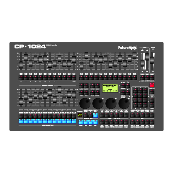
Seite 6: Geräteübersicht
• Einfachste Erstellung von Farb-, Gobo-, Fokus- und Effekt-Presets • Umfangreiche Moving Light Bibliothek • Szenen, Shows, Chasers und Presets lassen sich verschiedenen Speicherkarten zuordnen • 12 Events können gleichzeitig aufgerufen werden • Größtmögliche Auswahl an Speed Parameters für jede Speicherkarte Frontplatte •... -
Seite 7: Setup
Die Musiksteuerung kann entweder über die 6,3 mm Stereo-Klinkenbuchse oder das eingebaute Mikrofon erfolgen. Wenn der CP-1024 über ein Musiksignal an der Audio-Buchse arbeiten soll, verbinden Sie die Klinkenbuchse mit dem Audiosignal des Kopfhörerausganges bzw. des zweiten regelbaren Ausganges (falls vorhanden) des Mixers oder mit einem Lautsprecherausgang des Verstärkers. -
Seite 8: Bedienung
6. BEDIENUNG Über die Power-Taste lässt sich das Gerät ein- bzw. ausschalten. Bitte beachten Sie, dass die Power-Taste ca. 5 Sekunden lang gehalten werden muss, bis das Gerät abschaltet. Bitte führen Sie immer zuerst einen Software-Update auf die neueste Version durch. Bitte beachten Sie die Menübeschreibung im englischen Teil dieser Anleitung. -
Seite 9: Introduction
- download the latest version of the user manual from the Internet 1. INTRODUCTION Thank you for having chosen a FUTURELIGHT CP-1024. If you follow the instructions given in this manual, we are sure that you will enjoy this device for a long period of time. -
Seite 10: Operating Determinations
If the device has been exposed to drastic temperature fluctuation (e.g. after transportation), do not switch it on immediately. The arising condensation water might damage your device. Leave the device switched off until it has reached room temperature. Please make sure that there are no obvious transport damages. Should you notice any damages on the A/C connection cable or on the casing, do not take the device into operation and immediately consult your local dealer. -
Seite 11: Description Of The Device
Do not shake the device. Avoid brute force when installing or operating the device. When choosing the installation-spot, please make sure that the device is not exposed to extreme heat, moisture or dust. There should not be any cables lying around. You endanger your own and the safety of others! This device must never be operated or stockpiled in sourroundings where splash water, rain, moisture or fog may harm the device. - Seite 12 • 36 Multi function Quick access buttons • 39pcs 60mm faders • 12 dedicated playback faders with 99 pages • Grand master fader, and two additional A/B fader for dimmers • Go, stop and back buttons • Blackout, audio and beat buttons •...
-
Seite 13: Setup
The sound-control either works via the ¼” mono jack-socket or the built-in microphone. If the CP-1024 is supposed to work via a sound signal at the Audio In-socket, connect the ¼" jack socket with the sound signal of your headphones output or a second adjustable output (if existing) of your mixer, or with the loud-speaker output of your amplifier. -
Seite 14: Operation
6. OPERATION With the Power-button, you can switch the device on and off. Please note that you have to hold the Power button for approx. 5 seconds in order to switch the unit off. Please do always update this controller to the latest software version. 6.1 Menu System HOW TO START Control of the channels... -
Seite 15: Main Mode
MAIN MODE After turning on the controller the controller gets into the MAIN mode. Here the written programs, images can be called, started, their parameters can be set. ENTRY INTO THE MENU In the MAIN mode you can enter the menu by pressing the MENU button. UNIT SELECTION For being able to control a unit, you have to be able to select them. - Seite 16 SAVING THE PROGRAM IMAGE In the controller the program images can be saved into 12 registers, and each register has 10 turnable pages, so the images can be saved altogether to 12x10=120 memory locations. Maximum 90 images can be saved to each memory location, and you can manage from altogether 2,048 memory locations. A program image consists of the mask of the selected channels and the values of the channels.
- Seite 17 The palette can be used in such a way that different values can also be saved to the same channels of units of same type, so for example, the colours of the rainbow can be adjusted to 6 uniform units, and it can be saved to a palette.
- Seite 18 The switched on shape can be saved and called in later on. The shapes can be saved on the register buttons, altogether 12 buttons = 120 shapes. In each register one shape can be started from among the 10 pages, so altogether 12 shapes can run simultaneously. Start a shape in accordance with those described in the section USE OF SHAPES.
- Seite 19 POSITION By means thereof the position of the unit can be established in the stage. Upon pressing it from among the channels of the selected lights those that have been selected in the installation of the unit as ‘position’ will load their position value set there.
- Seite 20 JOG WHEELS (W1,W2,W3,W4) The channels of the selected units can be set primarily with the JOG discs. Always the four channels related to the current EFFECT button can be set with the JOG discs. The channels moved with the JOG disc get into the manual and the programmer memories.
- Seite 21 BPM (BLUE) When striking the BPM button according to the music rhythm severally, the controller remembers the struck pace and it will set the scene shifting according to it. The bpm value of the given pace can be read on the display.
- Seite 22 CLEAR Upon pressing it the manual and programmer memories are deleted. Those channels that are included in any running program, will execute its programs again. Upon pressing it the programmer memory is deleted. RECORD After pressing it the different events can be saved. Saving a program image: Setting the channels >...
- Seite 23 - Deleting the unit - Modification of the unit address - 2. Unit library - Manufacturers’ list - List of the units of the selected manufacturer - Entry of a new unit - Deleting the unit - Modification of the unit - 3.
- Seite 24 After the entry the manufacturers’ list can be seen. MANUFACTURERS’ LIST W1, UP-DOWN - selection of a manufacturer name ENTER - entry to the list of the current manufacturer’s units NEW - entering a new unit ESC - exit the menu item UNIT LIST W1, UP-DOWN - selection of a unit ENTER - entry to the edition of the current unit...
-
Seite 25: Shift-Button
To go to the next press the ENTER button. BLACK-OUT In order that the channel loads a value upon the activation of BLACK-OUT, the JOG1 should be selected, and then the open and closed black-out values of the channel should be selected with the JOG3 and JOG4 encoders. -
Seite 26: Language Selection
LANGUAGE SELECTION It is possible to select what language the controller displays the captions included in the display in. After login select the most appropriate one from the languages listed with the UP-DOWN buttons. You can exit the menu item with the ESC button. If meanwhile a change is made, the controller asks about saving the data, if not, it goes back to the menu. -
Seite 27: Manufacturing Date
Software version In the second line of the display the version number of the controller software can be read. DATE OF ISSUE OF THE SOFTWARE In the third line the date of issue of the software version can be read (year.month.day). SERIAL NUMBER In the fourth line of the display the serial number of the controller can be read. -
Seite 28: Problem Chart
7. PROBLEM CHART PROBLEM: CAUSE: REMEDY: No power. The power unit is not connected. Check the connection cable of the power unit and any extension-cables. 8. CLEANING AND MAINTENANCE DANGER TO LIFE! Disconnect from mains before starting maintenance operation! We recommend a frequent cleaning of the device. Please use a soft lint-free and moistened cloth. Never use alcohol or solvents! There are no servicable parts inside the device.