Futurelight ARC M/S Bedienungsanleitung

Verwandte Anleitungen für Futurelight ARC M/S


Inhaltszusammenfassung für Futurelight ARC M/S
- Seite 1 BEDIENUNGSANLEITUNG USER MANUAL ARC M/S DMX-controller © Copyright Für weiteren Gebrauch aufbewahren! Nachdruck verboten! Keep this manual for future needs! Reproduction prohibited!
-
Seite 2: Inhaltsverzeichnis
This user manual is valid for the article numbers 51834335, 51834340 Das neueste Update dieser Bedienungsanleitung finden Sie im Internet unter: You can find the latest update of this user manual in the Internet under: www.futurelight.com 2/38 00033924.DOC, Version 1.0... -
Seite 3: Dmx-Controller
- sich die letzte Version der Anleitung im Internet herunter laden 1. EINFÜHRUNG Wir freuen uns, dass Sie sich für einen FUTURELIGHT ARC-M/S entschieden haben. Wenn Sie nachfolgende Hinweise beachten, sind wir sicher, dass Sie lange Zeit Freude an Ihrem Kauf haben werden. -
Seite 4: Bestimmungsgemäße Verwendung
Das Gerät darf nicht in Betrieb genommen werden, nachdem es von einem kalten in einen warmen Raum gebracht wurde. Das dabei entstehende Kondenswasser kann unter Umständen Ihr Gerät zerstören. Lassen Sie das Gerät solange uneingeschaltet, bis es Zimmertemperatur erreicht hat! LEBENSGEFAHR! Lassen Sie den elektrischen Anschluss nur vom autorisierten Fachhandel ausführen! Der Aufbau entspricht der Schutzklasse III. -
Seite 5: Gerätebeschreibung
betrieben wird. Der Raum darf nur so stark mit Nebel gesättigt sein, dass eine gute Sichtweite von mindestens 10 m besteht. Die Umgebungstemperatur muss zwischen -5° C und +45° C liegen. Halten Sie das Gerät von direkter Sonneneinstrahlung (auch beim Transport in geschlossenen Wägen) und Heizkörpern fern. Die relative Luftfeuchte darf 50 % bei einer Umgebungstemperatur von 45°... -
Seite 6: Geräteübersicht
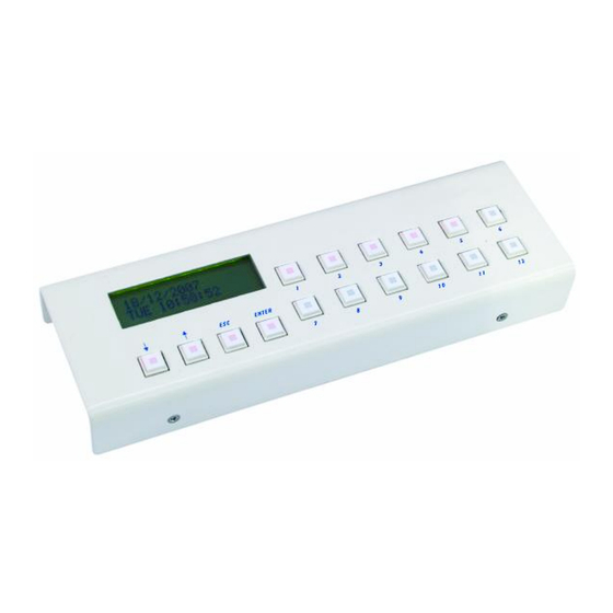
4.2 Geräteübersicht Übersicht über die Bedienelemente 1. DISPLAY: 2x16 Zeichen LCD-Display; Helligkeit und Kontrast können über das Menü eingestellt werden. 2. DONW-UP, ESC, ENTER: Menüsteuerung, Datenauswahl 3. EVENT 1-12: vorprogrammierte Events können mit den Event-Tasten gestartet werden. Wenn die LED nicht leuchtet, wurde dieser Taste kein Event zugewiesen. Bei roter LED ist ein Event zugewiesen. - Seite 7 Rückseite: USB-Anschluss Anschluss für Netz, DMX und Slave BATTERIE- 3V Batterie: Die eingebaute Uhr läuft auch nach einem Netzausfall batteriegepuffert weiter. Sobald die Batterie schwächer wird, blinkt das Uhr-Symbol im Display. Anschlussklemme:: Spannungsversorgung: Dieses Gerät lässt sich mit Gleich- und Wechselstrom betreiben. Deshalb ist die Polarität nicht so wichtig. Die Mindestanforderung an die Spannungsversorgung ist 10-24 V.
-
Seite 8: Setup
5. SETUP 5.1 Befestigung Vergewissern Sie sich vor der Montage, dass die Montagefläche mindestens die 5-fache Punktbelastung des Eigengewichtes des Gerätes aushalten kann. Der Installationsort muss so gewählt werden, dass das Gerät absolut plan an einem festen, erschütterungs- freien, schwingungsfreien und feuerfesten Ort befestigt werden kann. Mittels Wasserwaage muss überprüft werden, dass das Gerät absolut plan befestigt wurde. -
Seite 9: Bedienung
Achtung: Am letzten Projektor muss die DMX-Leitung durch einen Abschlusswiderstand abgeschlossen werden. Dazu wird ein 120 Widerstand in einen XLR-Stecker zwischen Signal (–) und Signal (+) eingelötet und in den DMX-Ausgang am letzten Gerät gesteckt. 6. BEDIENUNG Der Controller nimmt den Betrieb auf sobald Sie die Spannungsversorgung herstellen. Bitte führen Sie immer zuerst einen Software-Update auf die neueste Version durch. -
Seite 10: Technische Daten
ACHTUNG! Explosionsgefahr bei unsachgemäßem Auswechseln der Batterien. Nur durch denselben oder einen entsprechenden, vom Hersteller empfohlenen Typ ersetzen. Verbrauchte Batterien nach den Anweisungen des Herstellers beseitigen. Legen Sie die Batterie ein und achten Sie auf die richtige Polung. Schließen Sie das Gehäuse wieder. Im Interesse einer langen Batterielebensdauer sollten nur Alkaline-Typen verwendet werden. -
Seite 11: Introduction
- download the latest version of the user manual from the Internet 1. INTRODUCTION Thank you for having chosen a FUTURELIGHT ARC-M/S. If you follow the instructions given in this manual, we are sure that you will enjoy this device for a long period of time. -
Seite 12: Operating Determinations
DANGER TO LIFE! The electric connection must only be carried out by a qualified electrician! This device falls under protection-class III. The device always has to be operated with an appropriate transformer. The installer must always make sure to connect suitable terminals, connectors and cables! All valid instructions concerning the electric installation be adhered! Always disconnect from the mains, when the device is not in use or before cleaning it. -
Seite 13: Description Of The Device
Never use the device during thunderstorms. Over voltage could destroy the device. Always disconnect the device during thunderstorms. Operate the device only after having familiarized with its functions. Do not permit operation by persons not qualified for operating the device. Most damages are the result of unprofessional operation! Please use the original packaging if the device is to be transported. - Seite 14 4.2 Overview Overview on the control elements 1. DISPLAY: 2x16 character LCD display, the brightness and contrast of background light can be set in menu; by moving any of the control devices, information on changes is displayed. 2. DONW-UP, ESC, ENTER: Menu control, data selection 3.
- Seite 15 Rear panel USB connector Connect for Power, DMX, and slave BATTERY- 3V Battery: After power off will the exact time and date not forgotten by the controller. If the battery is discharged, then on the display will blink the ’clock’ icon. Connecor plugs:: Power supply: The controller can be operated from a power supply of AC and DC types, therefore the linking is not...
-
Seite 16: Setup
5. SETUP 5.1 Attachment Before attaching the device, make sure that the installation area can hold a minimum point load of 5 times the device's weight. The device must only be installed absolutely planar at a vibration-free, oscilation-free and fire-resistant location. -
Seite 17: Operation
6. OPERATION The controller starts running as soon as you connect the power supply. Please do always update this controller to the latest software version. REVIEW The controller is able to control channel 512 DMX, it is capable of sliding all its channels during a pre- programmed period. -
Seite 18: Channel Control
9. Click on the ‘Download’ icon or select the Setting/Start data downloading, downloading starts. 10. The state of downloading can be followed on the appearing process-marker, if it is finished, the caption ‘Downloading is ready’ appears, press the ‘OK‘ button. 11. -
Seite 19: Menu System
UP-DOWN buttons: the just flashing character position can be placed left or right, thus selecting the character to be modified. 1, 7 buttons: to select upper case (A-Z) 2, 8 buttons: to select lower case (a-z) 3, 9 buttons: to select numbers (0-9) 4, 10 buttons: to select among all the characters to be displayed 12 button: to insert space character, to push the cursor automatically to the right ESC or ENTER: to exit the word processor... - Seite 20 - 3. Controller data (Serial number and manufacturing date of the controller) MENU SYSTEM – MENU CODE ENTERING If the menu code is activated, on entering the menu it must be given to be able to enter the menu. This can be done with the buttons 1-12, and after entering the code, the button ENTER must be pushed.
- Seite 21 It is possible to protect controller data with menu code. If you want to protect your data against illegal person you should activate menu code. After activation if you want to step in menu system from automata mode you should first give the code and then you can reach menu and setup. Activate menu code select SETUP menu MENZU code position.
- Seite 22 The intensity of the LED’s can be set to optimal value in this menu item due to the existing light conditions in the different application areas. The set value of the total LED light illumination can be seen in the upper line, which can be seen on the LED’s of the 1-12 buttons as well.
- Seite 23 If no modification has been made in the menu item, then by pressing the ESC button the controller returns to the setup menu, if any modification has been made, the controller asks for the confirmation of saving the modification. By pressing down the “cancel” (DOWN) button the controller remains in the menu item, by pressing the “no” button (ESC) the controller returns to the menu without saving the modifications, while by pressing the “yes”...
- Seite 24 channel number Right lower Green Blue Controlled unit To this task it is advisable to create several groups: Name Channels Comment 1-12 All channel take part Left upper The left upper corner RGB channels Left lower The left lower corner RGB channels Right upper The right upper corner RGB channels Right lower...
- Seite 25 If after the tag ’CH:’ there is a sign ’---’, it means that currently there is no channel belonging to the group. If there is a number there, that channel is allocated to the group. With the buttons UP-DOWN you can see which channels belong to the group.
- Seite 26 MENU 5/2 – FUNCTION KEY The button 1-12 available on the controller can be programmed, that is the end-user can set which event to take place by pressing them. Besides this, the 12 buttons available on the so-called “slave” device, which is an accessory device that is available, can be set here.
- Seite 27 If you do not want to make more changes, press the ESC button, and if there have been any modifications, the controller asks for the confirmation of saving the modifications By pressing the button cancel (UP or DOWN) the controller stays in the menu point, by pressing the button no (ESC) the controller comes back to the menu without saving the modifications, while by pressing the button yes (ENTER) the controller saves the modifications, and comes back to the menu.
- Seite 28 In the upper row the number of the selected scene between 1 and 999 can be seen, in the bottom row the name of the scene can be found. With the buttons UP-DOWN you can select one particular scene of the 999.
- Seite 29 Channel selection ’All’ mode turns on, that is when setting the value the values of all the active channels will be modified at the same time Setting value It set the active channels to the value 0 To the next parameter you can always go by the button ENTER. The channel values will be constantly displayed on the dmx output, so the settings can be constantly seen on the attached devices as well.
- Seite 30 SEQUENCE 2/1 – EDITING Menu # UP/DOWN # Events # ENTER # Sequence # ENTER # Editing # ENTER In the upper row the number of the selected event between 1 and 999 can be seen, in the bottom row its name can be seen.
- Seite 31 DAILY PROGRAMME 2/2 – NAME Menü # UP/DOWN # Event # ENTER # Daily program # ENTER # Name # ENTER In the upper line you can see the number of the selected event in a range from 1 to 999, while in the bottom line you can see the name of the group.
- Seite 32 Always the parameters standing after the flashing colon can be set with the buttons UP-DOWN. While setting the step number and step time the buttons 1-7 and 2-8 are also at help, with which the values of hour and minute can be set. If you press the buttons UP and DOWN simultaneously and hold them pressed down in any parameter setting, the value switches back to the basic position, so it will be reset: Parameter Effect by pressing UP-DOWN simultaneously...
- Seite 33 By pressing the button cancel (UP or DOWN) the controller stays in the menu point, by pressing the button no (ESC) the controller comes back to the menu without saving the modifications, while by pressing the button yes (ENTER) the controller saves the modifications, and comes back to the menu. WEEKLY PROGRAMME 2/1 –...
- Seite 34 In a weekly programme it can be given, which daily programmes on the days of a month would be present. MONTHLY PROGRAMME 2/2 – NAME Menü # UP/DOWN # Event # ENTER # Weekly program # ENTER # Name # ENTER In the upper line you can see the number of the selected event in a range from 1 to 99, while in the bottom line you can see the name of the group.
- Seite 35 Parameter Effect by pressing UP-DOWN simultaneously Step number selection Step number will be set at 1 Event number selection Event number will be set at 1 A To the next parameter you can always go by the button ENTER. If you do not want to make more changes, press the ESC button, and if there have been any modifications, the controller asks for the confirmation of saving the modifications By pressing the button cancel (UP or DOWN) the controller stays in the menu point, by pressing the button no (ESC) the controller comes back to the menu without saving the modifications, while by pressing the...
-
Seite 36: Automatic Mode
Menu # UP/DOWN # Events # ENTER # Special programme # ENTER # Editing # ENTER In the upper row the number of the selected event between 1 and 999 can be seen, in the bottom row its name can be seen. With the buttons UP-DOWN you can select an event. If you have selected the event, which you would like to edit, press the button ENTER. -
Seite 37: Problem Chart
event will be started or stopped if it has been running. The current status of the selected event can be read at the end of the row. The scenes cannot be started or stopped; they can only be loaded! Maximum 12 of an event type can be started simultaneously; this however satisfies all demands necessary for the most complicated tasks as well. -
Seite 38: Technical Specifications
In order to have a long battery life, you should only use alcaline batteries. BATTERY DISPOSAL NOTICE Please dispose of old and used batteries properly. Batteries are hazardous waste and should not be disposed of with regular domestic waste! Please take old and used batteries to a collection center near you. 9.