SICK CDB405 Betriebsanleitung
C D B 4 0 5
A n s c h l u s s m o d u l f ü r
Barcodescanner CLV405
B e t r i e b s a n l e i t u n g
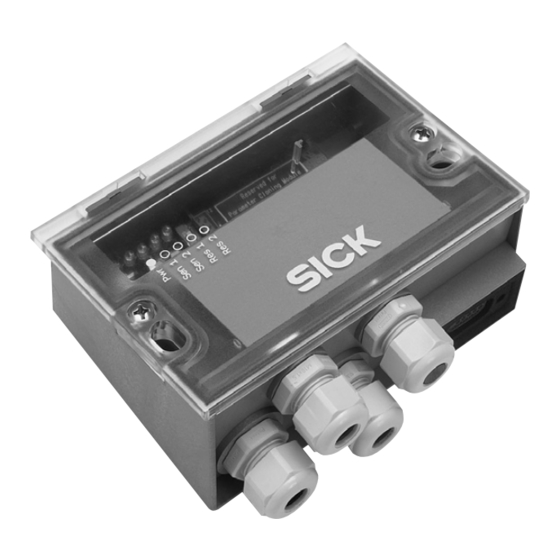
1. Produkteigenschaften
Kleines Anschlussmodul zum Anschluss eines CLV 405 an
■
Host, Peripherie und Stromversorgung
DC/DC-Wandler zur Spannungsversorgung des CLV 405 (DC 5 V)
■
Schalteingänge des CLV405 opto-entkoppelt und galvanisch
■
getrennt von der Versorgungsspannung des Anschlussmoduls
Schaltausgänge des CLV405 konvertiert von TTL-Pegel zu PNP-
■
schaltend gegen die Versorgungsspannung (High-side-Schalter)
9-pol. D-Sub-Stecker intern, für Anschluss der Aux-Schnittstelle
■
(RS-232) an PC zur Parametrierung/Diagnose des Scanners
Klemmen für Host-Schnittstelle, Schaltein- und -ausgänge,
■
Stromversorgung
Von außen sichtbar: LEDs zur Anzeige von aktiven Schaltein-/
■
-ausgängen sowie Schalterstellungen der Modulkonfiguration
Schutzart IP 65
■
Montierbar bei geschlossenem Deckel
■
Wartungsfrei
■
Weitere Produktinformationen, Programm „CLV-Connect":
Siehe www.sick.com
EG-Konformitätserklärung:
Auf Anforderung
2. Voraussetzungen zur Installation und Inbetriebnahme
Anschlusspläne in CLV-Connect (auf CD-ROM „Manuals &
■
Software Bar Code Scanners", die dem Scanner beiliegt, oder via
Internet unter www.sick.com)
Versorgungsspannung DC 18 ... 30 V, erzeugt nach IEC 742
■
3. Montage
Stets freier Zugang zum internen Stecker „AUX" erforderlich für
■
Zugriff auf Scanner (Parametrierung/Diagnose)
Maximale Leitungslänge zwischen CDB405 und Barcodescanner
■
CLV405 beim Einsatz von Verlängerungsleitungen beachten.
Siehe hierzu Kap. 5 Elektrische Installation, Seite 2.
Abgenommener Deckel mit Anschlussbild um 180° gedreht in
■
Parkposition arretierbar
Bohrungs- und Gehäusemaße siehe Maßbild (Seite 4),
Schraubendurchmesser: max. 4 mm.
8010866/S011/2009-10
CLV405
Licht-
schranke
(Lesetakt)
Photo reflex
"Sensor 1"
switch
(Reading clock)
"Sensor 2"
Schalter/switch
Teach-in matchcode
C o n n e c t i o n M o d u l e f o r
C LV 4 0 5 B a r C o d e S c a n n e r
O p e r a t i n g
1. Features
Compact connection module for connecting a CLV405 to the
■
host, peripheral equipment, and power supply
DC/DC converter for CLV405 power supply (5 V DC)
■
CLV405 switching inputs opto-decoupled and electrically isolated
■
from supply voltage of the module
CLV405 switching output levels TTL-to-PNP converted relative to
■
supply voltage (high side switch)
9-pin internal D-Sub plug, for connecting the Aux interface (RS
■
232) to a PC for configuring/diagnosing the scanner
Terminals for host interface, switching inputs/outputs, and
■
power supply
Externally visible LEDs for displaying active switching inputs and
■
outputs, as well as switch settings for module configuration
Enclosure rating IP 65
■
Installation possible with closed cover
■
Maintenance-free
■
Further Product Information, "CLV-Connect" PC Program:
See www.sick.com
EC Conformity Declaration:
On request
2. Installation and Commissioning Requirements
Connection diagrams in CLV-Connect (on the "Manuals &
■
Software Bar Code Scanners" CD-ROM, provided with the
scanner or from the Internet: www.sick.com)
18 to 30 V DC power supply generated in accord. with IEC 742.
■
3. Installation
Permanent access to internal "AUX" connector is required for
■
access to scanner (configuration/diagnosis)
Observe the maximum cable length between CDB405 and
■
CLV405 bar code scanner if extension cables are used.
See Chapter 5 Electrical Installation, page 2
Cover with connection diagram can be removed, rotated through
■
180°, and locked in park position
See dimensioned drawing (Page 4) for hole and housing
dimensions, max. screw diameter 4 mm (0.15 in).
© SICK AG · Division Auto Ident · Germany · All rights reserved
"Aux"
PC
CDB405
"Host"
HOST
"Result 1"
SPS/PLC
"Result 2"
SPS/PLC
"Result 3"
SPS/PLC
18 to 30 V DC
I n s t r u c t i o n s
1 # 4

Verwandte Anleitungen für SICK CDB405


Inhaltszusammenfassung für SICK CDB405
- Seite 1 Bohrungs- und Gehäusemaße siehe Maßbild (Seite 4), See dimensioned drawing (Page 4) for hole and housing Schraubendurchmesser: max. 4 mm. dimensions, max. screw diameter 4 mm (0.15 in). 8010866/S011/2009-10 © SICK AG · Division Auto Ident · Germany · All rights reserved 1 # 4...
- Seite 2 Host anschließen. Choose reference potential for switching inputs with switch S 3 ■ Bezugspotenzial für die Schalteingänge mit Schalter S 3 wählen ■ 2 # 4 © SICK AG · Division Auto Ident · Germany · All rights reserved 8010866/S011/2009-10...
- Seite 3 Datenleitung, Meterware, 4 x twisted pair, geschirmt, für 6005695 Data cable, bought to size, 4 x twisted pairs, shielded, for RS-232 und RS-422/485-Schnittstellen RS 232 and RS 422/485 interfaces 8010866/S011/2009-10 © SICK AG · Division Auto Ident · Germany · All rights reserved 3 # 4...
- Seite 4 PC automatisch wählen Aufbau, Klemmenbelegung/design, terminal assignment Maßbild/dimensioned drawing SICK AG · Waldkirch · Germany For local sales offices see www.sick.com 4 # 4 © SICK AG · Division Auto Ident · Germany · All rights reserved 8010866/S011/2009-10...