Inhaltsverzeichnis
Werbung
Verfügbare Sprachen
Verfügbare Sprachen
Quicklinks
Benutzerhandbuch
ONLINE XANTO S-Serie (ab 2012)
Deutschland
ONLINE USV-Systeme AG
Dreimühlenstraße 4
D-80469 München
Phone +49 (89) 2423990-10
Fax
+49 (89) 2423990-20
www.online-usv.de
XS6000+XS10000_manual_ger_eng_it_V1.1.2.doc
Modelle 6000 + 10000
Version: 1.1.2
Deutsch:
Seite
English:
Page
Italiano:
Pagina 145 - 216
Italien
ONLINE UPS-Systems S.r.l.
Via Gilera Ferruccio 110
I-20862 Arcore (MB)
Phone +39 (039) 2051444
Fax
+39 (039) 2051435
1 / 216
1 -
72
73 - 144
Schweiz
ONLINE USV-Systeme AG
Eigenheimstraße 11
CH-8304 Wallisellen (Zürich)
Phone
+41 (44) 9452829
Fax
+41 (44) 9453288
www.online-usv.ch
R. Kistler
Werbung
Kapitel
Inhaltsverzeichnis
Fehlerbehebung

Verwandte Anleitungen für Online USV XS6000


Inhaltszusammenfassung für Online USV XS6000
-
Seite 1: Benutzerhandbuch
Seite English: Page 73 - 144 Italiano: Pagina 145 - 216 Deutschland Italien Schweiz ONLINE USV-Systeme AG ONLINE UPS-Systems S.r.l. ONLINE USV-Systeme AG Dreimühlenstraße 4 Via Gilera Ferruccio 110 Eigenheimstraße 11 D-80469 München I-20862 Arcore (MB) CH-8304 Wallisellen (Zürich) Phone +49 (89) 2423990-10... - Seite 2 2 / 216 XS6000+XS10000_manual_ger_eng_it_V1.1.2.doc R. Kistler...
-
Seite 3: Inhaltsverzeichnis
4.5.5 Betriebsartwechsel der USV-Anlage ......... 36 Konfigurieren des Hocheffizienzbetriebs ......37 Konfigurieren der Bypass-Einstellungen ......38 Konfigurieren der Batterieeinstellungen ......39 4.8.1 Externe Batteriepakete ............39 4.8.2 Automatische Batterietests ..........39 Konfigurieren des automatische Neustarts ....... 40 3 / 216 XS6000+XS10000_manual_ger_eng_it_V1.1.2.doc R. Kistler... - Seite 4 9.1.3 Elektrische Ein- und Ausgänge ......... 65 9.1.4 Batterie ................67 9.1.5 Überbrückungszeit ............67 9.1.6 Kommunikationsoptionen ..........67 9.1.7 Umwelt und Sicherheit ............68 Rückansichten der USV-Anlagen ........69 CE Bestätigung ..............70 10. Garantie ..................71 4 / 216 XS6000+XS10000_manual_ger_eng_it_V1.1.2.doc R. Kistler...
- Seite 5 Abbildung 37: Ausbau XANTO S 10000, Schritt 1/3 ......53 Abbildung 38: Ausbau XANTO S 10000, Schritt 2/3 ......54 Abbildung 39: Ausbau XANTO S 10000, Schritt 3/3 ......54 Abbildung 40: XANTO S 6000 und 10000 Rückansicht ..... 69 5 / 216 XS6000+XS10000_manual_ger_eng_it_V1.1.2.doc R. Kistler...
-
Seite 6: Einleitung
E I N L E I T U N G Einleitung Die ONLINE USV-Systeme AG (ONLINE) gehört zu den führenden Herstellern von unterbrechungsfreien Stromversorgungen (USV). Seit 1988 beschäftigt sich das deutsche Unternehmen mit Entwick- lung, Fertigung, Vertrieb und Support von USV-Systemen. Nach ver- kauften Stückzahlen sind die Produkte der ONLINE die deutsche... -
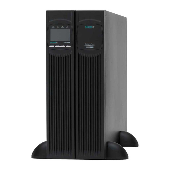
Seite 7: Abbildung 1: Xanto S 6000 Und 10000, Tower Installation
Slot für optionalen SNMP-Adapter, AS400- oder Relais-Karte Notaus-Funktion (REPO = Remote Emergency Power-Off) Wartungsbypass Abbildung 1: XANTO S 6000 und 10000, Tower Installation Abbildung 2: XANTO S 6000 und 10000, Rack Installation 7 / 216 XS6000+XS10000_manual_ger_eng_it_V1.1.2.doc R. Kistler... -
Seite 8: Sicherheitswarnungen
10000) und für Benutzer unzugänglich verlegt werden kön- nen. Es können maximal vier Batteriepakete je USV-Anlage installiert werden Vergewissern Sie sich vor dem Transport der USV-Anlage, dass die USV-Anlage von der Stromversorgung getrennt und ausgeschaltet ist 8 / 216 XS6000+XS10000_manual_ger_eng_it_V1.1.2.doc R. Kistler... - Seite 9 (siehe Wartung). Halten Sie nicht autorisiertes Personal von Batterien fern Die Batterien müssen ordnungsgemäß entsorgt werden. Hierbei sind die örtlichen Bestimmungen zu beachten Batterien dürfen nicht verbrannt werden. Es besteht Explosi- onsgefahr 9 / 216 XS6000+XS10000_manual_ger_eng_it_V1.1.2.doc R. Kistler...
-
Seite 10: Montage
Zubehörteile heraus. 2. Heben Sie die USV-Anlage vorsichtig aus dem äußeren Kar- ton. Hierzu sind zwei Personen notwendig. Bei der XANTO S 10000 verwenden Sie bitte die Griffe am inneren Karton (siehe Abbildung 3). 10 / 216 XS6000+XS10000_manual_ger_eng_it_V1.1.2.doc R. Kistler... -
Seite 11: Überprüfung Des Zubehörs
XANTO XANTO Beschreibung S 6000 S 10000 S 6000 S 10000 19"-Montagewinkel RS-232 Schnittstellenkabel Parallelkabel 10A Kaltgeräteverlängerung 16A Kaltgeräteverlängerung Bügel für Ausgangsanschlüsse Gehäusestütze für Tower-Montage Hilfswinkel für PDU Software DataWatch Bedienungsanleitung Tabelle 1: Lieferumfang 11 / 216 XS6000+XS10000_manual_ger_eng_it_V1.1.2.doc R. Kistler... -
Seite 12: Installation Als Tower
4. Entfernen Sie die Frontblende der USV-Anlage. Um die Front- blende zu entfernen, lösen Sie die beiden Schrauben an der oberen Seite. Schieben Sie die Frontblende nach oben und entfernen Sie sie vom Gehäuse. 12 / 216 XS6000+XS10000_manual_ger_eng_it_V1.1.2.doc R. Kistler... - Seite 13 Schieben Sie die Frontblende nach unten, bis sie in die Halte- rung an der unteren Seite des Gehäuses einrastet. Drehen Sie die beiden Schrauben an der oberen Seite wieder fest. 11. Fahren Sie mit dem Abschnitt Elektrische Installation fort. 13 / 216 XS6000+XS10000_manual_ger_eng_it_V1.1.2.doc R. Kistler...
-
Seite 14: Anschließen Der Batteriepakete
USV-Anlage (siehe Abbildung 5). Bis zu vier Bat- teriepakete können an die USV-Anlage angeschlossen wer- den. 7. Stellen Sie sicher, dass die Verbindungen der Batteriepakete sich nicht lösen. Angemessene Biegeradien und Zugentlas- tungen für alle Kabel müssen vorhanden sein. 14 / 216 XS6000+XS10000_manual_ger_eng_it_V1.1.2.doc R. Kistler... -
Seite 15: Abbildung 5: Xanto S 6000 Mit Bp, Tower (Frontansicht)
Vor dem Anschließen der Batteriepakete an die USV-Anlage sind die Batteriepakete zu erden. 1. Schließen Sie jedes Batteriepaket am Erdanschluss (Schrau- be auf der Rückseite) mittels eines zusätzlichen Kabels (mind. AWG 8, 6mm²) an Erdpotenzial an (siehe Abbildung 6 rechts unten). 15 / 216 XS6000+XS10000_manual_ger_eng_it_V1.1.2.doc R. Kistler... -
Seite 16: Abbildung 6: Xanto S 10000 Mit Bp, Tower (Rückansicht)
4. Einsetzen der Frontblenden: Schieben Sie die Frontblende nach unten, bis sie in die Halte- rung an der unteren Seite des Gehäuses einrastet. Drehen Sie die beiden Schrauben an der oberen Seite wieder fest. 16 / 216 XS6000+XS10000_manual_ger_eng_it_V1.1.2.doc R. Kistler... -
Seite 17: Installation Im Rack
Montieren Sie Batteriepakete direkt unter die USV-Anlage 1. Montage des Rack-Kits (siehe separate Montageanleitung). 2. Stellen Sie die USV-Anlage / das Batteriepaket auf eine ebe- ne, stabile Oberfläche. Die Vorderseite des Gehäuses ist zu Ihnen gerichtet. 17 / 216 XS6000+XS10000_manual_ger_eng_it_V1.1.2.doc R. Kistler... -
Seite 18: Abbildung 7: Frontblende Der Xanto S 6000 Und 10000
Abbildung 8). Abbildung 8: Batterieabdeckung der XANTO S 6000 und 10000 ACHTUNG Batterieeinschübe haben ein sehr hohes Gewicht. 5. Ziehen Sie die Batterieeinschübe nach vorne und benutzen Sie hierzu die Kunststofflaschen (siehe Abbildung 9). 18 / 216 XS6000+XS10000_manual_ger_eng_it_V1.1.2.doc R. Kistler... -
Seite 19: Abbildung 9: Batterieeinschübe Der Xanto S 6000 Und 10000
Verbinden Sie die Kabel schnell und fest. 11. Verbinden Sie die Steckverbindung für die internen Batterien der USV-Anlage. Drücken Sie beide Teile fest zusammen, um eine gute Verbindung zu gewährleisten. XANTO S 10000 nur die linke Seite. 19 / 216 XS6000+XS10000_manual_ger_eng_it_V1.1.2.doc R. Kistler... -
Seite 20: Anschließen Der Batteriepakete
Batterie-Steckverbindung der USV-Anlage ein. 4. Stecken Sie das Kabel des Batteriepaketes in den Batteriean- schluss der USV-Anlage, wie in Abbildung 10 dargestellt wird. Bis zu vier Batteriepakete können an die USV-Anlage ange- schlossen werden. 20 / 216 XS6000+XS10000_manual_ger_eng_it_V1.1.2.doc R. Kistler... -
Seite 21: Abbildung 10: Xanto S 6000 Mit Bp. Rackeinbau (Frontansicht)
Wiederholen Sie den Vorgang für jedes zusätzliche Batte- riepaket und die USV-Anlage. 7. Fahren Sie mit dem Abschnitt Elektrische Installation fort. XANTO S 10000 ACHTUNG Vor dem Anschließen der Batteriepakete an die USV-Anlage sind die Batteriepakete zu erden. 21 / 216 XS6000+XS10000_manual_ger_eng_it_V1.1.2.doc R. Kistler... -
Seite 22: Abbildung 11: Xanto S 10000 Mit Bp, Rackeinbau (Rückansicht)
Seite des Gehäuses einrastet. Drehen Sie die beiden Schrauben an der rechten Seite der Frontblende wieder fest. Wiederholen Sie den Vorgang für jedes zusätzliche Batte- riepaket und die USV-Anlage. 4. Fahren Sie mit dem Abschnitt Elektrische Installation fort. 22 / 216 XS6000+XS10000_manual_ger_eng_it_V1.1.2.doc R. Kistler... -
Seite 23: Elektrische Installation
Tabelle 2: Kabelquerschnitt (mehradrig) und Sicherungen 3.6.2 Klemmleiste Lösen Sie bitte die zwei Schrauben an der Klemmenabdeckung (sie- he Abbildung 12) für den Zugriff auf die Klemmleiste. Abbildung 12: Klemmenabdeckung XANTO S 6000 und 10000 23 / 216 XS6000+XS10000_manual_ger_eng_it_V1.1.2.doc R. Kistler... -
Seite 24: Anschlussvarianten
USV-Anlage mit getrenntem Normal- und Bypass-Anschluss Bypass Ausgang Eingang Abbildung 14: Getrennter Anschluss Eingang und Bypass getrennt USV-Anlage als Frequenzumrichter, ohne Bypass Keine Brücke! Eingang Ausgang Abbildung 15: Anschluss Frequenzumrichter, ohne Bypass Fahren Sie mit dem Abschnitt Inbetriebnahme fort. 24 / 216 XS6000+XS10000_manual_ger_eng_it_V1.1.2.doc R. Kistler... -
Seite 25: Inbetriebnahme
8. Falls externe Batteriepakete installiert sind, muss die Anzahl der externen Batteriepakete in der USV-Anlage eingestellt werden (siehe Betrieb – Menü Einstellungen). 9. Zum Ändern werksseitiger Voreinstellungen lesen Sie bitte den Abschnitt Menü Einstellungen im Kapitel Betrieb. 25 / 216 XS6000+XS10000_manual_ger_eng_it_V1.1.2.doc R. Kistler... - Seite 26 90% ihrer Kapazität aufladen. ONLINE empfiehlt, die Batterien nach der Installation oder nach längerer Lagerung 48 Stunden lang aufzuladen. Wenn zusätzliche Batteriepake- te installiert wurden, lesen Sie die Ladezeiten im Kapitel Technische Daten nach. 26 / 216 XS6000+XS10000_manual_ger_eng_it_V1.1.2.doc R. Kistler...
-
Seite 27: Betrieb
Menü zurückkehren. verlassen Taste länger als 1s drücken Scrollen Taste kurz drücken Scrollen Taste kurz drücken Menü, Einstellung Taste kurz drücken auswählen Einstellung Taste länger als 1s drücken. bestätigen Tabelle 3: Tastenbelegungen 27 / 216 XS6000+XS10000_manual_ger_eng_it_V1.1.2.doc R. Kistler... -
Seite 28: Startbildschirm
Batterie: Die Batterie wird als Balken dargestellt. Bei vollgeladenen Batterien erscheint der Balken komplett schwarz. Ausführliche Informationen sind im Batteriestatus enthalten. Drücken Sie hierzu zweimal die Taste. Ausgang: Ausgangsspannung -frequenz werden angezeigt. Last: Die angeschlossene Leistung (W und %) wird angzeigt. 28 / 216 XS6000+XS10000_manual_ger_eng_it_V1.1.2.doc R. Kistler... -
Seite 29: Hauptmenü
„Ereignisliste Löscht die Ereignisliste löschen“ „Auf Werkseinstel- Stellt die werkseitigen Einstellungen wieder lung zurücksetzen“ her. Identifikation - USV-Anlagen-Typ - Seriennummer - Firmware Einstellungen Zu Einzelheiten siehe Menü Einstellungen Tabelle 6. Tabelle 5: Hauptmenü 29 / 216 XS6000+XS10000_manual_ger_eng_it_V1.1.2.doc R. Kistler... -
Seite 30: Menü Einstellungen
Batteriebetrieb, falls die USV- Anlage in Betrieb ist. Der Bypassbetrieb wird deaktiviert. Sonderfall IT-System (frz. Isolé Terre): Z.B. in Krankenhäusern, Schiffen und Bahn, auf „De- aktiviert“ ändern. Sonst startet USV-Anlage nicht. Empfehlung: nur bei Sonderfall ändern. 30 / 216 XS6000+XS10000_manual_ger_eng_it_V1.1.2.doc R. Kistler... - Seite 31 Empfehlung: nicht ändern. -5, -4, …. +4, +5 LCD-Kontrast Empfehlung: an Erfordernisse anpassen. „Aktiviert“, „Deaktiviert“ „Deaktiviert“ Relaiskontakt Bei Benutzung der Relais-Einschubkarte oder des AS400 Interface auf „Aktiviert“ ändern. Empfehlung: an Erfordernisse anpassen. Tabelle 6: Menü Einstellungen 31 / 216 XS6000+XS10000_manual_ger_eng_it_V1.1.2.doc R. Kistler...
-
Seite 32: Betriebszustände
Die USV-Anlage wechselt unter folgenden Bedingungen in den By- passbetrieb: Wenn der Bypassbetrieb manuell aktiviert wird Wenn die USV-Anlage einen internen Fehler erkennt Wenn die USV-Anlage überhitzt ist Wenn die USV-Anlage eine Überlast aufweist 32 / 216 XS6000+XS10000_manual_ger_eng_it_V1.1.2.doc R. Kistler... -
Seite 33: Abbildung 21: Standbybetrieb
Software aktiviert werden. Abbildung 23: Frequenzumrichterbetrieb Warnmeldung Die USV-Anlage zeigt eine aktive Warnmeldung an. Ein akustisches Warnsignal ertönt jede Sekunde. Das Display wird rot. Beheben Sie umgehend die Ursache des Alarms (siehe Fehlerbehebung). Abbildung 24: Warnmeldung 33 / 216 XS6000+XS10000_manual_ger_eng_it_V1.1.2.doc R. Kistler... -
Seite 34: Abbildung 25: Fehlermeldung
Verringern Sie umgehend die ange- schlossene Last. Abbildung 26: Überlast Batterietest Die USV-Anlage führt einen Batterie- test durch. Abbildung 27: Batterietest Batteriewarnung Die USV-Anlage zeigt defekte oder nicht angeschlossene Batterien an. Abbildung 28: Batteriewarnung 34 / 216 XS6000+XS10000_manual_ger_eng_it_V1.1.2.doc R. Kistler... -
Seite 35: Starten Und Abschalten Der Usv-Anlage
Taste an der USV-Anlage mindestens eine Sekunde lang. Ein akustisches Signal ertönt. Ein paar Sekun- den später schaltet die USV-Anlage in den Batteriebetrieb. Falls das Versorgungsnetz zugeschaltet wird, schaltet die USV-Anlage ohne Unterbrechung in den Normalbetrieb. 35 / 216 XS6000+XS10000_manual_ger_eng_it_V1.1.2.doc R. Kistler... -
Seite 36: Abschalten Der Usv-Anlage Mit Versorgungsnetz
2. Nach kurzer Zeit schaltet die USV-Anlage ab. 4.5.5 Betriebsartwechsel der USV-Anlage Vom Normal- zum Bypassbetrieb: Drücken Sie die Taste an der USV-Anlage drei Sekunden lang. Vom Bypass- zum Normalbetrieb: Drücken Sie die Taste an der USV-Anlage eine Sekunde lang. 36 / 216 XS6000+XS10000_manual_ger_eng_it_V1.1.2.doc R. Kistler... -
Seite 37: Konfigurieren Des Hocheffizienzbetriebs
Nennfrequenz liegt. Sie können die Einstellung für einen anderen Prozentwert festlegen. Hocheff.freq. oberes Limit: Standardmäßig ist ein Wechsel in den Bypassbetrieb deaktiviert, wenn die gemessene Bypassfrequenz 5% über der Nennfrequenz liegt. Sie können die Einstellung für einen anderen Prozentwert festlegen. 37 / 216 XS6000+XS10000_manual_ger_eng_it_V1.1.2.doc R. Kistler... -
Seite 38: Konfigurieren Der Bypass-Einstellungen
Prozentwert festlegen. Bypassfrequenz oberes Limit: Standardmäßig ist ein Wechsel in den Bypassbetrieb deaktiviert, wenn die gemessene Bypassfrequenz 10% über der Nennfrequenz liegt. Sie können die Einstellung für ei- nen anderen Prozentwert festlegen. 38 / 216 XS6000+XS10000_manual_ger_eng_it_V1.1.2.doc R. Kistler... -
Seite 39: Konfigurieren Der Batterieeinstellungen
Während des Batterietests wechselt die USV-Anlage in den Batteriebetrieb und entlädt die Batterien kurz mit der vorhande- nen Last. HINWEIS Der Betriebszustand „Batteriebetrieb“ und der Hinweis „Bat- teriestand niedrig“ werden während eines Batterietests nicht angezeigt. 39 / 216 XS6000+XS10000_manual_ger_eng_it_V1.1.2.doc R. Kistler... -
Seite 40: Konfigurieren Des Automatische Neustarts
Die folgende Einstellung ist zusätzlich verfügbar: Autom. Neustart Überlast Nach Abschaltung der USV-Anlage im Überlastfall wird die USV- Anlage standardmäßig neu gestartet, sobald die Überlast entfernt ist. Sie können die Einstellung deaktivieren. 40 / 216 XS6000+XS10000_manual_ger_eng_it_V1.1.2.doc R. Kistler... -
Seite 41: Spezial-Funktionen
Bypassanschluss. Ein separater Bypassanschluss ist nicht möglich Jede USV-Anlage benötigt die gleiche Anzahl von Batterien (interne Batterien bzw. zusätzliche Batteriepakete) Hinsichtlich Kabelquerschnitt, Sicherungen und Klemmleiste wird auf den Abschnitt Elektrische Installation verwiesen 41 / 216 XS6000+XS10000_manual_ger_eng_it_V1.1.2.doc R. Kistler... -
Seite 42: Abbildung 29: Anschlussplan 1 Parallelschaltung
Bei einer Leitungslänge unter 10m dürfen die Leitungslängen zu den USV-Anlagen um maximal 20% differieren Bei einer Leitungslänge über 10m dürfen die Leitungslängen zu den USV-Anlagen um maximal 5% differieren Abbildung 29: Anschlussplan 1 Parallelschaltung 42 / 216 XS6000+XS10000_manual_ger_eng_it_V1.1.2.doc R. Kistler... -
Seite 43: Abbildung 30: Anschlussplan 2 Parallelschaltung
Maintenance Bypass for redundancy / parallel mode Eingangs-Schalter Eingangs-Schalter Input Breaker Input Breaker USV 1 USV 2 UPS 1 UPS 2 Ausgangs-Schalter Ausgangs-Schalter Output Breaker Output Breaker Haupt-Ausgangs-Schalter Main Output Breaker Verbraucher Load Abbildung 30: Anschlussplan 2 Parallelschaltung 43 / 216 XS6000+XS10000_manual_ger_eng_it_V1.1.2.doc R. Kistler... -
Seite 44: Inbetriebnahme Redundanz- / Parallelbetrieb
8. Schalten Sie die Ausgangsschalter der USV-Anlagen und an- schließend den Haupt-Ausgangsschalter ein. Die USV- Anlagen arbeiten jetzt im Redundanz- / Parallelbetrieb. 9. Schalten Sie die Last ein und überprüfen Sie, ob die ange- schlossene Last versorgt wird. 44 / 216 XS6000+XS10000_manual_ger_eng_it_V1.1.2.doc R. Kistler... -
Seite 45: Betriebsartwechsel Der Usv-Anlagen
Ist das Versorgungsnetz gestört, wechselt die USV-Anlage automa- tisch in den Batteriebetrieb (die Frequenz wird beibehalten). Die Last wird versorgt, solange die Batteriekapazität ausreichend ist. Nach Rückkehr des Versorgungsnetzes wechselt die USV-Anlage wieder in den Frequenzumrichterbetrieb. 45 / 216 XS6000+XS10000_manual_ger_eng_it_V1.1.2.doc R. Kistler... -
Seite 46: Kommunikation
K O M M U N I K A T I O N Kommunikation Abbildung 31: Kommunikationsoptionen XANTO S 6000 Abbildung 32: Kommunikationsoptionen XANTO S 10000 46 / 216 XS6000+XS10000_manual_ger_eng_it_V1.1.2.doc R. Kistler... -
Seite 47: Kommunikationsoptionen
Daten und ein ordnungsgemäßes Abschalten der Anlage aus. Die Belegung der Kabelanschlussstifte für die RS-232-Kommuni- kationsschnittstelle ist in Abbildung 33 dargestellt, die Funktionen der Anschlussstifte entnehmen Sie Tabelle 8. Abbildung 33: RS-232 Kommunikationsschnittstelle (DB-9-Stecker) 47 / 216 XS6000+XS10000_manual_ger_eng_it_V1.1.2.doc R. Kistler... -
Seite 48: Slot Für Schnittstellenkarten
Gebäudemanagement. PHXNOV-I Relais-Einschubkarte Meldung von Batteriebetrieb, Normalbetrieb und Batteriekapazität niedrig. Signaleingang zur USV-Abschaltung. PHXAS400I AS400-Interface Meldung von USV-Alarm, Bypass aktiv, Batteriespannung niedrig, Inverter außer Funktion und Netzausfall. Signaleingang zur USV-Abschaltung. Tabelle 9: Schnittstellenkarten 48 / 216 XS6000+XS10000_manual_ger_eng_it_V1.1.2.doc R. Kistler... -
Seite 49: Notaus-Funktion (Repo)
Lassen Sie den REPO-Stecker im Notaus-Anschluss an der USV-Anlage eingesteckt, wenn die Notaus-Funktion nicht benötigt wird Testen Sie die Notaus-Funktion immer, bevor eine kritische Last angeschlossen wird. Hiermit vermeiden Sie eine verse- hentliche Lastabschaltung 49 / 216 XS6000+XS10000_manual_ger_eng_it_V1.1.2.doc R. Kistler... -
Seite 50: Datawatch Software
Als Client- / Server-Anwendung arbeitet DataWatch in Netzwerken und auf lokalen Workstations. Mittels optionalem RCCMD-Agent (Remote Console Command) lassen sich mehrere an einer USV- Anlage angeschlossene Server ohne zusätzliche Hardware über das Netzwerk ansprechen und steuern. 50 / 216 XS6000+XS10000_manual_ger_eng_it_V1.1.2.doc R. Kistler... -
Seite 51: Wartung
Nach Ablauf der zu erwartenden Lebensdauer haben weiter verwendete Batterien häufig deutlich verringer- te Laufzeiten. Tauschen Sie die Batterien spätestens alle fünf Jahre aus, damit die Anlage zu jeder Zeit mit optimaler Leistung laufen kann. 51 / 216 XS6000+XS10000_manual_ger_eng_it_V1.1.2.doc R. Kistler... -
Seite 52: Ausbau Und Tausch Von Usv-Anlagen
2. Schrauben Sie den Hilfswinkel an die PDU und trennen Sie diese von der USV-Anlage. Lösen Sie hierzu 3 Schrauben. Schrauben Sie die PDU an das Rack (siehe Abbildung 35). Abbildung 35: Ausbau XANTO S 6000, Schritt 2/3 52 / 216 XS6000+XS10000_manual_ger_eng_it_V1.1.2.doc R. Kistler... -
Seite 53: Abbildung 36: Ausbau Xanto S 6000, Schritt 3/3
5. Der Einbau der neuen USV-Anlage erfolgt in umgekehrter Reihenfolge. XANTO S 10000 1. Entfernen Sie Sicherungsabdeckung vom Wartungsbypass entfernen. Lösen Sie hierzu 2 Schrauben. Schalten Sie den Wartungsbypass auf Bypass (siehe Abbildung 37). Abbildung 37: Ausbau XANTO S 10000, Schritt 1/3 53 / 216 XS6000+XS10000_manual_ger_eng_it_V1.1.2.doc R. Kistler... -
Seite 54: Abbildung 38: Ausbau Xanto S 10000, Schritt 2/3
Racks und ziehen Sie die USV-Anlage aus dem Rack (siehe Abbildung 39). Abbildung 39: Ausbau XANTO S 10000, Schritt 3/3 4. Schrauben Sie die 19“ Montagewinkel von der USV-Anlage 5. Der Einbau der neuen USV-Anlage erfolgt in umgekehrter Reihenfolge. 54 / 216 XS6000+XS10000_manual_ger_eng_it_V1.1.2.doc R. Kistler... -
Seite 55: Lagerung Von Usv-Anlagen / Batterien
Abschalten der USV-Anlage und ohne Trennen der angeschlosse- nen Lasten ausgetauscht werden. Falls Sie die USV-Anlage vor dem Auswechseln der Batterien lieber vom Netz trennen möchten, lesen Sie den Abschnitt „Abschalten der USV-Anlage mit Versorgungsnetz“. 55 / 216 XS6000+XS10000_manual_ger_eng_it_V1.1.2.doc R. Kistler... - Seite 56 Anschlüssen der Batterie vor. Der Versuch, eigen- ständig die Verkabelung der Batterie zu verändern, kann zu ernsthaften Verletzungen führen Die Batterien befinden sich hinter der Frontblende der USV-Anlage bzw. des Batteriepaketes. Die Batterien sind wegen der besseren Handhabung zusammen verpackt. 56 / 216 XS6000+XS10000_manual_ger_eng_it_V1.1.2.doc R. Kistler...
- Seite 57 8. Die interne Batterie-Steckverbindung bzw. die externe Batte- rieverbindung (Batteriepaket XANTO S 10000) muss wieder angeschlossen werden. 9. Setzen Sie die Frontblende der USV-Anlage / dem Batteriepa- ket wieder ein. 10. Fahren Sie mit dem Abschnitt „Testen der neuen Batterien“ fort. 57 / 216 XS6000+XS10000_manual_ger_eng_it_V1.1.2.doc R. Kistler...
-
Seite 58: Testen Der Neuen Batterien
Batterien müssen ordnungsgemäß entsorgt werden. Infor- mieren Sie sich über die Entsorgungsvorschriften vor Ort Öffnen oder beschädigen Sie die Batterie(n) nicht. Die Batte- riesäure kann Augen und Haut angreifen, sowie Vergiftungen bewirken 58 / 216 XS6000+XS10000_manual_ger_eng_it_V1.1.2.doc R. Kistler... -
Seite 59: Fehlerbehebung
1. Drücken Sie die Taste mindestens eine Sekunde lang, um die Menüoptionen zu aktivieren. Taste, bis „EREIGNISAUFZEICHNUNG“ 2. Drücken Sie die angezeigt wird. 3. Drücken Sie die Taste, um die Liste aktiver Statusmeldun- gen anzuzeigen. 59 / 216 XS6000+XS10000_manual_ger_eng_it_V1.1.2.doc R. Kistler... -
Seite 60: Warn- Und Fehlermeldungen
Trennen Sie die Last von der USV- Ausgang gang der USV-Anlage Anlage. Schalten Sie die USV- Kurzschluss Anlage aus. Überprüfen Sie die Last auf einen Kurzschluss. Wenn der Kurzschluss beseitigt ist, schalten Sie die USV-Anlage wieder ein. 60 / 216 XS6000+XS10000_manual_ger_eng_it_V1.1.2.doc R. Kistler... - Seite 61 USV-Anlage ab. Wenden Sie sich an den Support. 94 Fehler Interner Fehler Wenden Sie sich an den Support. Eingang Fehler A1 Fehler Interner Speicherfehler Wenden Sie sich an den Support. Interner Speicher der USV-Anlage. Fehler 61 / 216 XS6000+XS10000_manual_ger_eng_it_V1.1.2.doc R. Kistler...
- Seite 62 Überprüfen Sie in den Einstellungen Hocheff.betrieb nicht erlaubt jeder USV-Anlage die Energiestrate- n. erlaubt gie. EC Warnung Last ungleich verteilt Verteilen Sie die Last auf beide USV- Last asym. Anlagen gleichmäßig. Tabelle 10: Warn- und Fehlermeldungen 62 / 216 XS6000+XS10000_manual_ger_eng_it_V1.1.2.doc R. Kistler...
-
Seite 63: Sonstige Fehlerursachen
Überprüfen Sie die Qualität des By- wechselt nicht ist nicht geeignet. pass-Netzstroms. den Bypassbetrieb. Der Bypassbetrieb ist Prüfen Sie, Bypass- deaktiviert. Einstellungen richtig konfiguriert sind. (siehe „Konfigurieren der Bypass- Einstellungen“). Tabelle 11: Sonstige Fehlerursachen 63 / 216 XS6000+XS10000_manual_ger_eng_it_V1.1.2.doc R. Kistler... -
Seite 64: Stummschalten Des Alarmsignals
Hardware-Hotline: +49 (89) 242 39 90 - 18 Kostenloser 24h-Vorabaustausch Interaktiver USV-Konfigurator im Internet 2 Jahre Vollgarantie, optionale Verlängerung Unbürokratische 14 Tage Geld-zurück-Garantie Hohe Warenverfügbarkeit und dichtes Distributionsnetz Weitere Informationen: www.online-usv.de 64 / 216 XS6000+XS10000_manual_ger_eng_it_V1.1.2.doc R. Kistler... -
Seite 65: Technische Daten
100% Last Strom spannungen * XANTO S 6000 230V / 208V, 220V, 176 - 276VAC 230V, 240V XANTO S 10000 230V / 208V, 220V, 176 - 276VAC 230V, 240V Tabelle 15: Elektrische Ein- und Ausgangsleistung 65 / 216 XS6000+XS10000_manual_ger_eng_it_V1.1.2.doc R. Kistler... - Seite 66 Spannungs- Sinuskurve kurvenform Harmonische <2% THD bei linearer Last, < 5% THD bei nicht-linearer Last Verzerrung Umschaltzeit Online-Betrieb: 0ms (unterbrechungsfrei) Hocheffizienzbetrieb: 10ms maximal (wegen Netzstromverlust) Leistungsfaktor Lastspitzenfaktor 3 zu 1 Tabelle 17: Elektrische Ausgangsleistung 66 / 216 XS6000+XS10000_manual_ger_eng_it_V1.1.2.doc R. Kistler...
-
Seite 67: Batterie
9.1.6 Kommunikationsoptionen Slot für optionale 1 x Slot für Schnittstellenkarten Schnittstellen Optionale Schnittstellenkarten: SNMP-Adapter Basic (Artikel-Nr. DW7SNMP30) SNMP-Adapter Professional (Artikel-Nr. DW5SNMP30) Relais-Einschubkarte (Artikel-Nr. PHXNOV-I) AS400-Interface (Artikel-Nr. PHXAS400I) Kommunikations- RS-232 (DB-9) schnittstellen Tabelle 21: Kommunikationsoptionen 67 / 216 XS6000+XS10000_manual_ger_eng_it_V1.1.2.doc R. Kistler... -
Seite 68: Umwelt Und Sicherheit
0 - 95% nicht kondensierend Betriebshöhe Bis zu 1000 Meter über NN = 100% Ausgangsleistung Leistungsminderung von 1% je weitere 100m Hörbares Geräusch <55dBA bei 1 Meter typisch Tabelle 22: Angaben zu Umwelt und Sicherheit 68 / 216 XS6000+XS10000_manual_ger_eng_it_V1.1.2.doc R. Kistler... -
Seite 69: Rückansichten Der Usv-Anlagen
T E C H N I S C H E D A T E N Rückansichten der USV-Anlagen Beschreibung der Anschlüsse siehe Abbildung 31 und Abbildung 32 Kommunikation. Abbildung 40: XANTO S 6000 und 10000 Rückansicht 69 / 216 XS6000+XS10000_manual_ger_eng_it_V1.1.2.doc R. Kistler... -
Seite 70: Ce Bestätigung
T E C H N I S C H E D A T E N CE Bestätigung 70 / 216 XS6000+XS10000_manual_ger_eng_it_V1.1.2.doc R. Kistler... -
Seite 71: Garantie
G A R A N T I E Garantie Die ONLINE USV-Systeme AG (ONLINE) gewährleistet, dass dieses Produkt für die Dauer von zwei Jahren ab Kaufdatum frei von Mate- rial- und Fertigungsfehlern ist. Die Verpflichtung von ONLINE gemäß dieser Garantie ist auf die Reparatur oder den Ersatz (Entscheidung trifft ONLINE) jeglicher defekter Produkte begrenzt. - Seite 72 72 / 216 XS6000+XS10000_manual_ger_eng_it_V1.1.2.doc R. Kistler...
-
Seite 73: User Manual
Page English: Page 73 - 144 Italiano: Pagina 145 - 216 Germany Italy Switzerland ONLINE USV-Systeme AG ONLINE UPS-Systems S.r.l. ONLINE USV-Systeme AG Dreimühlenstraße 4 Via Gilera Ferruccio 110 Eigenheimstraße 11 D-80469 Munich I-20862 Arcore (MB) CH-8304 Wallisellen (Zurich) Phone +49 (89) 2423990-10... - Seite 74 74 / 216 XS6000+XS10000_manual_ger_eng_it_V1.1.2.doc R. Kistler...
- Seite 75 Configuring the HE mode ..........109 Configuring the bypass settings ........110 Configuring the battery settings ........111 4.8.1 External battery modules ..........111 4.8.2 Automatic battery tests ............ 111 Configuring the automatic restart ........112 75 / 216 XS6000+XS10000_manual_ger_eng_it_V1.1.2.doc R. Kistler...
- Seite 76 9.1.4 Battery ................139 9.1.5 Autonomy time ..............139 9.1.6 Communication options ........... 139 9.1.7 Environment and safety ..........140 Back views of the UPS systems ........141 CE conformity ..............142 10. Warranty ................. 143 76 / 216 XS6000+XS10000_manual_ger_eng_it_V1.1.2.doc R. Kistler...
- Seite 77 Figure 38: Removing the XANTO S 10000, step 2/3 ....... 126 Figure 39: Removing the XANTO S 10000, step 3/3 ....... 126 Figure 40: XANTO S 6000 and XANTO S 10000 rear view ..... 141 77 / 216 XS6000+XS10000_manual_ger_eng_it_V1.1.2.doc R. Kistler...
-
Seite 78: Introduction
I N T R O D U C T I O N Introduction ONLINE USV-Systeme AG (ONLINE) is one of the leading manufac- turers of Uninterruptible Power Supplies (UPS). Since 1988, the German company has specialised in the development, manufacture and sales &... -
Seite 79: Figure 1: Xanto S 6000 And 10000, Tower Installation
Slot for optional SNMP adapter, AS400 card or relay card Emergency-off function (REPO = Remote Emergency Power- Off) Maintenance Switch Figure 1: XANTO S 6000 and 10000, Tower Installation Figure 2: XANTO S 6000 and 10000, Rack Installation 79 / 216 XS6000+XS10000_manual_ger_eng_it_V1.1.2.doc R. Kistler... -
Seite 80: Safety Warnings
A maximum of four battery modules per UPS system can be installed Make sure that the UPS system is switched off and discon- nected from the power supply before transporting the UPS system 80 / 216 XS6000+XS10000_manual_ger_eng_it_V1.1.2.doc R. Kistler... - Seite 81 (see Maintenance). Keep unauthorised personnel away from batteries The batteries must be disposed of properly. Observe the local regulations for proper disposal Batteries may not be incinerated. There is a risk of explosion 81 / 216 XS6000+XS10000_manual_ger_eng_it_V1.1.2.doc R. Kistler...
-
Seite 82: Installation
2. Carefully lift the UPS system out of the outer carton. Two peo- ple are required for this. For the XANTO S 10000, please use the handles on the inner carton (see Figure 3). 82 / 216 XS6000+XS10000_manual_ger_eng_it_V1.1.2.doc R. Kistler... -
Seite 83: Checking The Accessories
Parallel cable 10A low-heat devices power cord 16A low-heat devices power cord Bracket for output connections Housing bracket for tower installation Support bracket for PDU DataWatch software Operating instructions Table 1: Scope of supply 83 / 216 XS6000+XS10000_manual_ger_eng_it_V1.1.2.doc R. Kistler... -
Seite 84: Installation As Tower
XANTO S 6000 (see Figure 4). 4. Remove the front cover of the UPS system. To remove the front cover, unscrew the two screws on the upper side. Slide the front cover up and remove it from the housing. 84 / 216 XS6000+XS10000_manual_ger_eng_it_V1.1.2.doc R. Kistler... - Seite 85 10. Inserting the front cover: Slide the front cover down until it engages in the holder on the underside of the housing. Retighten the two screws on the up- per side. 11. Proceed with section Electrical installation. 85 / 216 XS6000+XS10000_manual_ger_eng_it_V1.1.2.doc R. Kistler...
-
Seite 86: Connecting The Battery Modules
UPS system (see Figure 5). Up to four batteries can be connected to the UPS system. 7. Ensure that the connections of the battery modules do not loosen. There must be sufficient bending radius and tension relief for all cables. 86 / 216 XS6000+XS10000_manual_ger_eng_it_V1.1.2.doc R. Kistler... -
Seite 87: Figure 5: Xanto S 6000Va With Bp, Tower (Front View)
1. Connect each battery module to the ground connection (screw on the rear side) using an additional cable (at least AWG 8, 6mm²) at the ground potential (see Figure 6 bottom right). 87 / 216 XS6000+XS10000_manual_ger_eng_it_V1.1.2.doc R. Kistler... -
Seite 88: Figure 6: Xanto S 10000 With Bp, Tower (Rear View)
Proceed here analogue to the turning of the display (see page 87/5). 4. Inserting the front covers: Slide the front cover down until it engages in the holder on the underside of the housing. Retighten the two screws on the up- per side. 88 / 216 XS6000+XS10000_manual_ger_eng_it_V1.1.2.doc R. Kistler... -
Seite 89: Installation In The Rack
Mount the battery modules directly under the UPS system 1. Installation of the rack kit (see separate installation instructions). 2. Place the UPS system/battery module on a level, stable sur- face. The front side of the housing is facing you. 89 / 216 XS6000+XS10000_manual_ger_eng_it_V1.1.2.doc R. Kistler... -
Seite 90: Figure 7: Front Cover Of The Xanto S 6000 And 10000
4. Remove the battery cover of the batteries (see Figure 8) Figure 8: Battery cover of the XANTO S 6000 and 10000 CAUTION Battery module inserts are very heavy. 5. Pull the battery modules forwards using the plastic tabs (see Figure 9) 90 / 216 XS6000+XS10000_manual_ger_eng_it_V1.1.2.doc R. Kistler... -
Seite 91: Figure 9: Battery Module Inserts Of The Xanto S 6000 And 10000
This is normal and does not pose a hazard to people. Connect the cables quickly and firmly. 11. Connect the plug connection again for the internal batteries. Press both parts together firmly to ensure a good connection. XANTO S 10000 only the left side. 91 / 216 XS6000+XS10000_manual_ger_eng_it_V1.1.2.doc R. Kistler... -
Seite 92: Connecting The Battery Modules
4. Stick the cable of the battery module into the battery connec- tion of the UPS system as shown in Figure 10). Up to four bat- teries can be connected to the UPS system. 92 / 216 XS6000+XS10000_manual_ger_eng_it_V1.1.2.doc R. Kistler... - Seite 93 Repeat the procedure for each additional battery module. 7. Proceed with section Electrical installation. XANTO S 10000 CAUTION Before connecting the battery modules to the UPS system, the battery modules must be grounded. 93 / 216 XS6000+XS10000_manual_ger_eng_it_V1.1.2.doc R. Kistler...
-
Seite 94: Figure 11: Xanto S 10000 With Bp, Rack Installation (Rear View)
Retighten the two screws on the right side of the front cover. Repeat the procedure for each additional battery module and the UPS system. 4. Proceed with section Electrical installation. 94 / 216 XS6000+XS10000_manual_ger_eng_it_V1.1.2.doc R. Kistler... -
Seite 95: Electrical Installation
Table 2: Cable cross-section (multicore) and fuses 3.6.2 Terminal strip Please unscrew the two screws at the terminal cover (see Figure 12) for access to the terminal strip. Figure 12: Terminal cover XANTO S 6000 and 10000 95 / 216 XS6000+XS10000_manual_ger_eng_it_V1.1.2.doc R. Kistler... -
Seite 96: Connection Variants
UPS system with separate normal and bypass connection Bypass Output Line input Figure 14: Separate connection line input and bypass separated UPS system as converter, without bypass jumper! Line input Output Figure 15: Connection converter without bypass Proceed with section Commissioning. 96 / 216 XS6000+XS10000_manual_ger_eng_it_V1.1.2.doc R. Kistler... -
Seite 97: Commissioning
8. If external battery modules are installed, the number of exter- nal battery modules must be set in the UPS system (see "Op- eration – Settings menu"). 9. To change the factory settings, please read the Settings menu section in the Operation chapter. 97 / 216 XS6000+XS10000_manual_ger_eng_it_V1.1.2.doc R. Kistler... - Seite 98 ONLINE recommends charging the batteries for 48 hours after installation or after a longer peri- od of storage. If additional battery modules were installed, please refer to the charging times in the Technical Data chapter. 98 / 216 XS6000+XS10000_manual_ger_eng_it_V1.1.2.doc R. Kistler...
-
Seite 99: Operation
Press the button longer than 1 second Scroll Press the button briefly Scroll Press the button briefly Select menu, setting Press the button briefly Confirm setting Press the button longer than 1 second. Table 3: Button assignments 99 / 216 XS6000+XS10000_manual_ger_eng_it_V1.1.2.doc R. Kistler... -
Seite 100: Start Screen
More detailed information is included in the battery status. To see this information, press the button. UPS output: Output voltage and frequency are displayed. Load: The connected power (W and %) are displayed. 100 / 216 XS6000+XS10000_manual_ger_eng_it_V1.1.2.doc R. Kistler... -
Seite 101: Main Menu
- Firmware Settings Please refer to the Settings menu for details Dry contact signal "Enabled", "Disabled" input With relay card or AS400 interface "Ena Recommendation: Adapt to requiremen Table 6. Table 5: Main menu 101 / 216 XS6000+XS10000_manual_ger_eng_it_V1.1.2.doc R. Kistler... -
Seite 102: Settings Menu
Bypass mode is disabled. Special case IT system (Fr. Isolé Terre): E.G. in hospitals, ships and trains, change it to "Disabled." Otherwise does not start up UPS. Recommendation: Change only in special cases. 102 / 216 XS6000+XS10000_manual_ger_eng_it_V1.1.2.doc R. Kistler... - Seite 103 Recommendation: Do not change. -5, -4, …. +4, +5 LCD Contrast Recommendation: Adapt to requirements. Dry contact signal "Enabled", "Disabled" "Disabled" input With relay card or AS400 interface "Enabled". Recommendation: Adapt to requirements. Table 6: Settings menu 103 / 216 XS6000+XS10000_manual_ger_eng_it_V1.1.2.doc R. Kistler...
-
Seite 104: Operating States
The UPS system will switch to bypass mode under the following conditions: If the bypass mode is activated manually If the UPS system detects an internal fault If the UPS system is overheated If the UPS system has an overload 104 / 216 XS6000+XS10000_manual_ger_eng_it_V1.1.2.doc R. Kistler... -
Seite 105: Figure 21: Standby Mode
The UPS system is displaying an ac- tive warning message. An audio warning signal is emitted every sec- ond. The display turns red. Rectify the cause of the alarm imme- diately (see Troubleshooting). Figure 24: Warning message 105 / 216 XS6000+XS10000_manual_ger_eng_it_V1.1.2.doc R. Kistler... -
Seite 106: Figure 25: Error Message
Figure 26: Overload Battery test The UPS system is performing a bat- tery test. Figure 27: Battery test Battery warning The UPS system displays defective batteries or batteries which are not connected. Figure 28: Battery warning 106 / 216 XS6000+XS10000_manual_ger_eng_it_V1.1.2.doc R. Kistler... -
Seite 107: Starting And Switching Off The Ups System
An audio signal will be emitted. Several seconds later, the UPS system switches to battery mode. If the mains power supply switches on again, the UPS system will switch to nor- mal mode without interruption. 107 / 216 XS6000+XS10000_manual_ger_eng_it_V1.1.2.doc R. Kistler... -
Seite 108: Switching Off The Ups System With Mains Power Supply
Changing operating modes of the UPS system From normal to bypass mode: Press the button on the UPS sys- tem for 3 seconds. From bypass to normal mode: Press the button on the UPS supply for one second. 108 / 216 XS6000+XS10000_manual_ger_eng_it_V1.1.2.doc R. Kistler... -
Seite 109: Configuring The He Mode
HE frequency high limit: By default, switching to bypass mode is disabled if the measured bypass frequency lies 5% above the nomi- nal frequency. You can specify the setting for a different percentage value. 109 / 216 XS6000+XS10000_manual_ger_eng_it_V1.1.2.doc R. Kistler... -
Seite 110: Configuring The Bypass Settings
Bypass frequency high limit: By default, switching to bypass mode is disabled if the measured bypass frequency lies 10% above the measured nominal frequency. You can specify the setting for a dif- ferent percentage value. 110 / 216 XS6000+XS10000_manual_ger_eng_it_V1.1.2.doc R. Kistler... -
Seite 111: Configuring The Battery Settings
During the battery test, the UPS system switches to battery mode and briefly discharges the batteries with the available load. NOTE The operating mode "Battery mode" and the "Battery level low" message are not displayed during a battery test. 111 / 216 XS6000+XS10000_manual_ger_eng_it_V1.1.2.doc R. Kistler... -
Seite 112: Configuring The Automatic Restart
The following setting is additionally available: Automatic restart overload If the UPS system switches off due to an overload, the UPS system will restart by default as soon as the overload is removed. You can disable the setting. 112 / 216 XS6000+XS10000_manual_ger_eng_it_V1.1.2.doc R. Kistler... -
Seite 113: Special Functions
A separate bypass connection is not possible Each UPS system requires the same number of batteries (internal batteries or additional battery modules) Refer to the Electrical installation section for information about cable cross-section, fuses and terminal strip 113 / 216 XS6000+XS10000_manual_ger_eng_it_V1.1.2.doc R. Kistler... -
Seite 114: Figure 29: Connection Plan 1 Parallel Switching
20% For a line length above 10 m, the line lengths to the UPS systems may differ by a maximum of 5% Figure 29: Connection plan 1 parallel switching 114 / 216 XS6000+XS10000_manual_ger_eng_it_V1.1.2.doc R. Kistler... -
Seite 115: Figure 30: Connection Plan 2 Parallel Switching
Maintenance Bypass for redundancy / parallel mode Eingangs-Schalter Eingangs-Schalter Input Breaker Input Breaker USV 1 USV 2 UPS 1 UPS 2 Ausgangs-Schalter Ausgangs-Schalter Output Breaker Output Breaker Haupt-Ausgangs-Schalter Main Output Breaker Verbraucher Load Figure 30: Connection plan 2 parallel switching 115 / 216 XS6000+XS10000_manual_ger_eng_it_V1.1.2.doc R. Kistler... -
Seite 116: Commissioning Redundant/Increase Mode
8. Switch on the output switches of the UPS systems and then switch on the main output switch. The UPS systems are now working in redundant/increase mode. 9. Switch the load on and check whether the connected load is supplied. 116 / 216 XS6000+XS10000_manual_ger_eng_it_V1.1.2.doc R. Kistler... -
Seite 117: Switching Modes On The Ups Systems
(the frequency is maintained). The load will be supplied as long as there is sufficient battery capaci- ty. After the mains power supply returns, the UPS system switches back to convertor mode. 117 / 216 XS6000+XS10000_manual_ger_eng_it_V1.1.2.doc R. Kistler... -
Seite 118: Communication
C O M M U N I C A T I O N Communication Figure 31: Communication options XANTO S 6000 Figure 32: Communication options XANTO S 10000 118 / 216 XS6000+XS10000_manual_ger_eng_it_V1.1.2.doc R. Kistler... -
Seite 119: Communication Options
Figure 33; refer to Function Input / Output Transmission data (TxD) Output Receive data (RxD) Input Ground for the functions of the connection pins. Table 8 Figure 33: RS-232 communication port (DB-9 connector) 119 / 216 XS6000+XS10000_manual_ger_eng_it_V1.1.2.doc R. Kistler... -
Seite 120: Slot For Interface Cards
Message from battery mode, normal mode and battery capacity low. Signal input for UPS shutdown. PHXAS400I AS400 interface Message from UPS alarm, bypass active, battery voltage low, inverter inoperable and power failure. Signal input for UPS shutdown. Table 9: Interface cards 120 / 216 XS6000+XS10000_manual_ger_eng_it_V1.1.2.doc R. Kistler... -
Seite 121: Emergency-Off Function (Repo)
Leave the REPO connector in the emergency-off connector plugged into the UPS system if the emergency-off function is not required Always test the emergency-off function before a critical load is connected. This will prevent an unintended load breaking 121 / 216 XS6000+XS10000_manual_ger_eng_it_V1.1.2.doc R. Kistler... -
Seite 122: Datawatch Software
As client/server application, DataWatch works in networks and on lo- cal workstations. Using the optional RCCMD agent (Remote Console Command), multiple servers connected to a UPS system can be activated and controlled via the network without additional hardware. 122 / 216 XS6000+XS10000_manual_ger_eng_it_V1.1.2.doc R. Kistler... -
Seite 123: Maintenance
After expiration of the expected service life, batteries which continue to be used frequently have reduced running times. Replace the batteries every five years at the latest so that the system can provide optimal power at any time. 123 / 216 XS6000+XS10000_manual_ger_eng_it_V1.1.2.doc R. Kistler... -
Seite 124: Removing And Replacing Ups Systems
2. Screw the support bracket to the PDU and disconnect this from the UPS system. Unscrew the three screws to do this. Screw the PDU to the rack (see Figure 35). Figure 35: Removing the XANTO S 6000, step 2/3 124 / 216 XS6000+XS10000_manual_ger_eng_it_V1.1.2.doc R. Kistler... -
Seite 125: Figure 36: Removing The Xanto S 6000, Step 3/3
1. Remove the safety cover from the maintenance which. Unscrew the two screws to do this. Switch the maintenance switch to bypass (see Figure 37). Figure 37: Removing the XANTO S 10000, step 1/3 125 / 216 XS6000+XS10000_manual_ger_eng_it_V1.1.2.doc R. Kistler... -
Seite 126: Figure 38: Removing The Xanto S 10000, Step 2/3
Figure 39: Removing the XANTO S 10000, step 3/3 4. Unscrew and remove the 19" mounting bracket from the UPS system. 5. The installation of the new UPS system is done in the reverse order. 126 / 216 XS6000+XS10000_manual_ger_eng_it_V1.1.2.doc R. Kistler... -
Seite 127: Storing Ups Systems/Batteries
UPS system and without having to disconnect the connected loads. If you would prefer to disconnect the UPS system from the mains be- fore replacing the batteries, please read the "Switching off the UPS system with mains power supply" section. 127 / 216 XS6000+XS10000_manual_ger_eng_it_V1.1.2.doc R. Kistler... - Seite 128 Attempting to modify the cabling of the batteries yourself can lead to serious injuries The batteries are located behind the front cover of the UPS system or the battery module. For better handling, the batteries are pack- aged together. 128 / 216 XS6000+XS10000_manual_ger_eng_it_V1.1.2.doc R. Kistler...
- Seite 129 8. The internal battery plug connection or the external battery connection (battery module XANTO S 10000) must be con- nected again. 9. Reinsert the front cover of the UPS system/battery module. 10. Proceed with section "Testing the new batteries". 129 / 216 XS6000+XS10000_manual_ger_eng_it_V1.1.2.doc R. Kistler...
-
Seite 130: Testing The New Batteries
Batteries must be disposed of properly. Inform yourself about the local disposal regulations Do not open or damage the batteries. The battery acid can attack the eyes and skin as well as cause poisoning 130 / 216 XS6000+XS10000_manual_ger_eng_it_V1.1.2.doc R. Kistler... -
Seite 131: Troubleshooting
1. Press the button for at least one second to enable the menu options. 2. Press the button until "EVENT LOG" is displayed.. 3. Press the button to display a list of active status messages. 131 / 216 XS6000+XS10000_manual_ger_eng_it_V1.1.2.doc R. Kistler... -
Seite 132: Warning And Error Messages
Output Short Circuit the UPS system system. Switch off the UPS sys- tem. Check the load for a short circuit. After the short circuit has been rectified, switch the UPS sys- tem on again. 132 / 216 XS6000+XS10000_manual_ger_eng_it_V1.1.2.doc R. Kistler... - Seite 133 Switch off the supply voltage of the UPS system. Please contact support. 94 Fault Internal fault Please contact support. Byp Relay Sticked A1 Fault Internal EEPROM fault Please contact support. Fatal EEPROM of the UPS system. Fault 133 / 216 XS6000+XS10000_manual_ger_eng_it_V1.1.2.doc R. Kistler...
- Seite 134 Check the power strategy in the ECO setting in par- settings of each UPS system. allel system EC Warning Load distributed Distribute the load on both UPS Load unbalance unequally systems evenly. Table 10: Warning and error messages 134 / 216 XS6000+XS10000_manual_ger_eng_it_V1.1.2.doc R. Kistler...
-
Seite 135: Other Folds Causes
The bypass mode is de- Check whether the bypass settings activated. configured correctly. (see "Configuring the bypass settings" Table 11: Other fault causes 135 / 216 XS6000+XS10000_manual_ger_eng_it_V1.1.2.doc R. Kistler... -
Seite 136: Muting The Alarm Signal
Interactive UPS configurator on the Internet 2 years factory warrantee, optional extension Hassle-free 14-day money-back guarantee High availability of goods and extensive distribution network Visit us on the web at: www.online-usv.de for more information. 136 / 216 XS6000+XS10000_manual_ger_eng_it_V1.1.2.doc R. Kistler... -
Seite 137: Technical Data
176 - 276 VAC 28 A 230 V, 240 V XANTO S 10000 230 V / 208 V, 220 V, 176 - 276 VAC 46 A 230 V, 240 V Table 15: Electrical input and output power 137 / 216 XS6000+XS10000_manual_ger_eng_it_V1.1.2.doc R. Kistler... - Seite 138 <2% THD for linear load, < 5% THD for nonlinear load distortion Switching time Online operation: 0 ms (uninterrupted) HE mode: 10 ms maximum (due to loss of mains current) Power factor Peak load factor 3 to 1 Table 17: Electrical output power 138 / 216 XS6000+XS10000_manual_ger_eng_it_V1.1.2.doc R. Kistler...
-
Seite 139: Battery
Optional interface cards: SNMP adapter basic (article number: DW7SNMP30) SNMP adapter professional (article number: DW5SNMP30) Relay module (article number: PHXNOV-I) AS400 interface (article number: PHXAS400I) Communication inter- RS-232 (DB-9) faces Table 21: Communication options 139 / 216 XS6000+XS10000_manual_ger_eng_it_V1.1.2.doc R. Kistler... -
Seite 140: Environment And Safety
Up to 1000 m above sea level = 100% output power Power reduction of 1% for each additional 100 m Audible noise 55 dBA at 1 m typical Table 22: Environment and safety specifications 140 / 216 XS6000+XS10000_manual_ger_eng_it_V1.1.2.doc R. Kistler... -
Seite 141: Back Views Of The Ups Systems
T E C H N I C A L D A T A Back views of the UPS systems Description of the connections, see Figure 31 and Figure 32 Com- munication. Figure 40: XANTO S 6000 and XANTO S 10000 rear view 141 / 216 XS6000+XS10000_manual_ger_eng_it_V1.1.2.doc R. Kistler... -
Seite 142: Ce Conformity
T E C H N I C A L D A T A CE conformity 142 / 216 XS6000+XS10000_manual_ger_eng_it_V1.1.2.doc R. Kistler... -
Seite 143: Warranty
W A R R A N T Y Warranty ONLINE USV-Systeme AG (ONLINE) hereby warrants this product to be free from defects in material and workmanship for a period of two years from the date of purchase. The obligation of ONLINE under this warranty is limited to the replacement or repair of any product which proves upon our examination to be defective. - Seite 144 144 / 216 XS6000+XS10000_manual_ger_eng_it_V1.1.2.doc R. Kistler...
-
Seite 145: Manuale Dell'utente
Page English: Page 73 - 144 Italiano: Pagina 145 - 216 Germania Italiano Svizzera ONLINE USV-Systeme AG ONLINE UPS-Systems S.r.l. ONLINE USV-Systeme AG Dreimühlenstraße 4 Via Gilera Ferruccio 110 Eigenheimstraße 11 D-80469 München I-20862 Arcore (MB) CH-8304 Wallisellen (Zürich) Phone +49 (89) 2423990-10... - Seite 146 146 / 216 XS6000+XS10000_manual_ger_eng_it_V1.1.2.doc R. Kistler...
- Seite 147 Configurazione della modalità “ECO mode” ....181 Configurazione delle impostazioni di bypass ....182 Configurazione delle impostazioni delle batterie ..... 183 4.8.1 Pacchi batterie esterni ............. 183 4.8.2 Test automatici delle batterie .......... 183 Configurazione del riavvio automatico ......184 147 / 216 XS6000+XS10000_manual_ger_eng_it_V1.1.2.doc R. Kistler...
- Seite 148 9.1.4 Batteria ................211 9.1.5 Autonomia ............... 211 9.1.6 Opzioni di comunicazione ..........212 9.1.7 Ambiente e sicurezza ............212 Viste posteriori dei sistemi UPS ........213 Dichiarazione CE............. 214 10. Garanzia ................. 215 148 / 216 XS6000+XS10000_manual_ger_eng_it_V1.1.2.doc R. Kistler...
- Seite 149 Figura 37: Smontaggio del sistema XANTO S 10000, 1/3 ....197 Figura 38: Smontaggio del sistema XANTO S 10000, 2/3 ....198 Figura 39: Smontaggio del sistema XANTO S 10000, 3/3 ....198 Figura 40: XANTO S 6000 e 10000, vista posteriore ....... 213 149 / 216 XS6000+XS10000_manual_ger_eng_it_V1.1.2.doc R. Kistler...
-
Seite 150: Introduzione
I N T R O D U Z I O N E Introduzione ONLINE USV-Systeme AG (ONLINE) è un'azienda tedesca leader nel settore dei gruppi di continuità (UPS), attiva dal 1988 nello sviluppo, produzione, commercializzazione e assistenza di sistemi UPS. L'azien- da è... - Seite 151 Funzione di arresto d'emergenza remoto (REPO = Remote Emergency Power-Off) Bypass di manutenzione Figura 1: XANTO S 6000 e 10000, Installazione Tower Figura 2: XANTO S 6000 e 10000, Installazione in armadio rack 151 / 216 XS6000+XS10000_manual_ger_eng_it_V1.1.2.doc R. Kistler...
-
Seite 152: Avvertenze Di Sicurezza
(XANTO S 6000) o sul lato posteriore (XANTO S 10000) e in modo che siano inaccessibili agli utenti. È possibile installare al massimo quattro pacchi batterie per ogni UPS Prima di trasportare l’UPS assicurarsi che questo sia scolle- gato dall'alimentazione elettrica e disattivato 152 / 216 XS6000+XS10000_manual_ger_eng_it_V1.1.2.doc R. Kistler... - Seite 153 Le batterie devono essere smaltite conformemente alle disposizioni. A tal fine, osservare le norme locali vigenti in materia Le batterie non devono essere bruciate. In tal caso sussiste il pericolo di esplosione 153 / 216 XS6000+XS10000_manual_ger_eng_it_V1.1.2.doc R. Kistler...
-
Seite 154: Montaggio
1. Aprire il cartone esterno, rimuovere le parti in polistirolo e prelevare gli accessori. 2. Prelevare l’UPS dal cartone esterno sollevandolo con cautela. A tal fine sono necessarie due persone. Per il sistema XANTO 154 / 216 XS6000+XS10000_manual_ger_eng_it_V1.1.2.doc R. Kistler... -
Seite 155: Controllo Degli Accessori
Cavo d'interfaccia RS-232 Cavo parallelo Prolunga alimentazione 10A Prolunga alimentazione 16A Staffa per prese di uscita Supporto della scatola per il montaggio Tower Staffe angolari per PDU Software DataWatch Manuale dell’utente Tabella 1: Dotazione della fornitura 155 / 216 XS6000+XS10000_manual_ger_eng_it_V1.1.2.doc R. Kistler... -
Seite 156: Installazione Tower
XANTO S 6000 (vedi Figura 4). 4. Rimuovere il pannello frontale dell’UPS. Per rimuovere il pan- nello frontale, allentare entrambe le viti sul lato superiore. Spingere il pannello frontale verso l'alto e rimuoverlo dalla scatola dell'UPS. 156 / 216 XS6000+XS10000_manual_ger_eng_it_V1.1.2.doc R. Kistler... - Seite 157 Spingere il pannello frontale verso il basso finché questo scat- ta in sede nel supporto sul lato inferiore della scatola. Serrare nuovamente a fondo le due viti sul lato superiore. 11. Proseguire con il paragrafo Installazione elettrica. 157 / 216 XS6000+XS10000_manual_ger_eng_it_V1.1.2.doc R. Kistler...
-
Seite 158: Collegamento Dei Pacchi Batterie
(vedi Figura 5). È possibile collegare all’UPS fino a quattro pacchi batterie. 7. Assicurarsi che i collegamenti dei pacchi batterie non si allen- tino. Verificare che siano presenti e scarichi della trazione che i raggi di curvatura non siano troppo stretti. 158 / 216 XS6000+XS10000_manual_ger_eng_it_V1.1.2.doc R. Kistler... - Seite 159 1. Collegare ogni pacco batterie alla messa a terra (vite sul lato posteriore) mediante un cavo supplementare (min. AWG 8, 6mm²) sul potenziale di terra (vedi Figura 6 in basso a destra). 159 / 216 XS6000+XS10000_manual_ger_eng_it_V1.1.2.doc R. Kistler...
- Seite 160 4. Montaggio del pannello frontale del pacco batterie: Spingere il pannello frontale verso sinistra finché questo scatta in sede nel supporto sul lato sinistro del cabinet. Serrare nuo- vamente a fondo le due viti sul lato destro del pannello frontale. 160 / 216 XS6000+XS10000_manual_ger_eng_it_V1.1.2.doc R. Kistler...
-
Seite 161: Installazione In Armadio Rack
Montare i pacchi batterie direttamente sotto l’UPS 1. Montaggio del kit rack (vedi istruzioni di montaggio separate). 2. Posizionare l’UPS / il pacco batterie su una superficie piana e stabile. Il lato anteriore della scatola deve essere rivolto verso l'utente. 161 / 216 XS6000+XS10000_manual_ger_eng_it_V1.1.2.doc R. Kistler... - Seite 162 Figura 8: Copertura batteria del sistema XANTO S 6000 e 10000 ATTENZIONE Gli inserti batterie hanno un peso estremamente elevato. 5. Tirare gli inserti batterie in avanti utilizzando le linguette in plastica (vedi Figura 9) 162 / 216 XS6000+XS10000_manual_ger_eng_it_V1.1.2.doc R. Kistler...
- Seite 163 Collegare saldamente i cavi in modo rapido. 11. Ripristinare il collegamento a innesto per le batterie interne. Stringere assieme entrambi gli elementi per garantire un buon collegamento. XANTO S 10000 solo il lato sinistro. 163 / 216 XS6000+XS10000_manual_ger_eng_it_V1.1.2.doc R. Kistler...
-
Seite 164: Collegamento Dei Pacchi Batterie
4. Inserire il cavo del pacco batterie nell'attacco della batteria dell’UPS, come illustrato nella Figura 10. È possibile collegare all’UPS fino a quattro pacchi batterie. 164 / 216 XS6000+XS10000_manual_ger_eng_it_V1.1.2.doc R. Kistler... - Seite 165 Ripetere la procedura per ogni pacco batterie supplementare. 7. Proseguire con il paragrafo Installazione elettrica. XANTO S 10000 ATTENZIONE Prima di collegare i pacchi batterie all’UPS, collegare a mas- sa i pacchi batterie. 165 / 216 XS6000+XS10000_manual_ger_eng_it_V1.1.2.doc R. Kistler...
- Seite 166 Serrare nuo- vamente a fondo le due viti sul lato destro del pannello fronta- Ripetere la procedura per ogni pacco batterie supplementare. 4. Proseguire con il paragrafo Installazione elettrica. 166 / 216 XS6000+XS10000_manual_ger_eng_it_V1.1.2.doc R. Kistler...
-
Seite 167: Installazione Elettrica
Tabella 2: Sezioni del cavo (multicore) e fusibili 3.6.2 Morsettiera Allentare le due viti sulla copertura dei morsetti per accedere alla morsettiera (vedi Figura 12). Figura 12: Copertura morsetti dei sistemi XANTO S 6000 e 10000 167 / 216 XS6000+XS10000_manual_ger_eng_it_V1.1.2.doc R. Kistler... -
Seite 168: Varianti Di Collegamento
Figura 14: Connessioni di ingresso e di bypass separato Sistema UPS come convertitore di frequenza, senza bypass Nessun ponticello! Ingresso Uscita Figura 15: Connessioni convertitore di frequenza senza bypass Proseguire con il paragrafo Messa in funzione. 168 / 216 XS6000+XS10000_manual_ger_eng_it_V1.1.2.doc R. Kistler... -
Seite 169: Messa In Funzione
8. Se sono installati pacchi batterie esterni, il loro numero deve essere impostato nel sistema UPS (vedi Funzionamento – Menu Settings). 9. Per modificare le impostazioni di fabbrica leggere il paragrafo Menu Settings al capitolo Funzionamento. 169 / 216 XS6000+XS10000_manual_ger_eng_it_V1.1.2.doc R. Kistler... - Seite 170 ONLINE consiglia di ricaricare le batterie per 48 ore dopo l'installazione o dopo un lungo periodo di immagazzinamento. Se sono stati installati pacchi batterie supplementari, consultare i tempi di ricarica riportati al capi- tolo Dati tecnici. 170 / 216 XS6000+XS10000_manual_ger_eng_it_V1.1.2.doc R. Kistler...
-
Seite 171: Funzionamento
Premere brevemente il tasto. Scorrimento Premere brevemente il tasto. Selezione di un menu/ Premere brevemente il tasto. un'impostazione Conferma dell'im- Premere il tasto per più di 1 secondo. postazione Tabella 3: Assegnazione dei tasti 171 / 216 XS6000+XS10000_manual_ger_eng_it_V1.1.2.doc R. Kistler... -
Seite 172: Schermata Iniziale
. UPS output (Uscita UPS): visualizza tensione e frequenza di uscita. Load (Carico): visualizza la potenza assorbita dal carico (in valore assoluto (W) e percentuale (%)). 172 / 216 XS6000+XS10000_manual_ger_eng_it_V1.1.2.doc R. Kistler... -
Seite 173: Menu Principale
- Firmware Settings Per maggiori dettagli, vedi Menu Settings Dry contact signal "Enabled", "Disabled" input Cambiare con scheda relè inseribileo o AS400-interfaccia su "Enabled". Recommendation: Adapt to requiremen Tabella 6. Tabella 5: Menu principale 173 / 216 XS6000+XS10000_manual_ger_eng_it_V1.1.2.doc R. Kistler... -
Seite 174: Menu Settings
UPS è in funzione. La modalità Bypass viene disattivata. Caso particolare sistema IT (Fr. Isolé Terre): ES. in ospedali, navi e treni, modificarlo in "Disabilitato". In caso contrario, non si avvia UPS. Raccomandazione: modificare solo in casi particolari. 174 / 216 XS6000+XS10000_manual_ger_eng_it_V1.1.2.doc R. Kistler... - Seite 175 -5, -4, …. +4, +5 LCD Contrast Raccomandazione: adattare alle esigenze. Dry contact signal "Enabled", "Disabled" "Disabled" input Cambiare con scheda relè inseribileo o AS400-interfaccia su "Enabled". Recommendation: Adapt to requirements. Tabella 6: Menu Settings 175 / 216 XS6000+XS10000_manual_ger_eng_it_V1.1.2.doc R. Kistler...
-
Seite 176: Stati Di Esercizio
L’UPS commuta sulla modalità Bypass nelle seguenti condizioni: quando la modalità Bypass viene attivata manualmente quando l’UPS rileva un guasto interno quando l’UPS si è surriscaldato quando l’UPS rileva un sovraccarico 176 / 216 XS6000+XS10000_manual_ger_eng_it_V1.1.2.doc R. Kistler... - Seite 177 L’UPS visualizza un messaggio di al- larme. Ogni secondo risuona un se- gnale acustico di allarme. Il display diventa di colore rosso. Eliminare immediatamente la causa dell'allarme (vedi Eliminazione dei guasti). Figura 24: Messaggio di allarme 177 / 216 XS6000+XS10000_manual_ger_eng_it_V1.1.2.doc R. Kistler...
- Seite 178 Ridurre immediatamente carico collegato. Figura 26: Sovraccarico Battery test L’UPS esegue un test delle batterie. Figura 27: Test batterie Allarme sulla batteria L’UPS visualizza batterie difettose o non collegate. Figura 28: Allarme sulla batteria 178 / 216 XS6000+XS10000_manual_ger_eng_it_V1.1.2.doc R. Kistler...
-
Seite 179: Avvio E Spegnimento Del Sistema Ups
3. Premere per almeno un secondo il tasto emesso un segnale acustico. Dopo pochi secondi l’PS commu- ta sulla modalità di funzionamento a batteria. Se la rete di ali- mentazione viene attivata, l’UPS commuta sul funzionamento normale senza alcuna interruzione. 179 / 216 XS6000+XS10000_manual_ger_eng_it_V1.1.2.doc R. Kistler... -
Seite 180: Spegnimento Dell'ups Connesso Con La Rete
Commutazione della modalità d'esercizio dell’UPS 4.5.5 Dal funzionamento normale alla modalità Bypass: premere per tre secondi il tasto sul sistema UPS. Dalla modalità Bypass al funzionamento normale: premere per un secondo il tasto sul sistema UPS. 180 / 216 XS6000+XS10000_manual_ger_eng_it_V1.1.2.doc R. Kistler... -
Seite 181: Configurazione Della Modalità "Eco Mode
HE frequency high limit (Limite superioredi frequenza in alta eff.): in genere la commutazione sulla modalità Bypass è disattivata quando la frequenza di bypass è superiore a quella nominale del 5%. L'impostazione può essere modificata su un altro valore percen- tuale. 181 / 216 XS6000+XS10000_manual_ger_eng_it_V1.1.2.doc R. Kistler... -
Seite 182: Configurazione Delle Impostazioni Di Bypass
Bypass): in genere la commutazione sulla modalità Bypass è disatti- vata quando la frequenza di bypass misurata è superiore alla fre- quenza nominale del 10%. L'impostazione può essere modificata su un altro valore percentuale. 182 / 216 XS6000+XS10000_manual_ger_eng_it_V1.1.2.doc R. Kistler... -
Seite 183: Configurazione Delle Impostazioni Delle Batterie
Durante il test delle batterie l’UPS commuta sulla modalità di funzionamento a batteria e scarica brevemente le batterie con il cari- co presente. AVVERTENZA Durante un test delle batterie non vengono visualizzati lo sta- to di esercizio "Battery Mode" e l'avvertenza "Battery Low". 183 / 216 XS6000+XS10000_manual_ger_eng_it_V1.1.2.doc R. Kistler... -
Seite 184: Configurazione Del Riavvio Automatico
Inoltre è disponibile la seguente impostazione: Automatic overload restart Dopo lo spegnimento dell’UPS in caso di sovraccarico, in genere l’UPS viene riavviato non appena il sovraccarico è stato eliminato. Questa impostazione può essere disattivata. 184 / 216 XS6000+XS10000_manual_ger_eng_it_V1.1.2.doc R. Kistler... -
Seite 185: Funzioni Speciali
Ogni UPS deve avere lo stesso numero di batterie (batterie interne o pacchi batterie aggiuntivi) Per informazioni sulla sezione del cavo, sui fusibili e sulla morsettiera fare riferimento al paragrafo Installazione elettrica 185 / 216 XS6000+XS10000_manual_ger_eng_it_V1.1.2.doc R. Kistler... - Seite 186 Nel caso di una lunghezza del cavo superiore a 10 m, le lun- ghezze dei cavi verso gli UPS possono differire al massimo del 5% Figura 29: Schema di collegamento 1 Collegamento in parallelo 186 / 216 XS6000+XS10000_manual_ger_eng_it_V1.1.2.doc R. Kistler...
- Seite 187 Eingangs-Schalter Input Breaker Input Breaker USV 1 USV 2 UPS 1 UPS 2 Ausgangs-Schalter Ausgangs-Schalter Output Breaker Output Breaker Haupt-Ausgangs-Schalter Main Output Breaker Verbraucher Load Figura 30: Schema di collegamento 2 Collegamento in parallelo 187 / 216 XS6000+XS10000_manual_ger_eng_it_V1.1.2.doc R. Kistler...
-
Seite 188: Messa In Funzione Nella Modalità Ridondante/Parallelo
Menu Settings). 8. Attivare gli interruttori di uscita degli UPS, quindi l'interruttore di uscita principale.Gli UPS funzionano ora in modalità ridon- dante/in parallelo. 9. Attivare il carico e verificare che il carico collegato venga alimentato. 188 / 216 XS6000+XS10000_manual_ger_eng_it_V1.1.2.doc R. Kistler... -
Seite 189: Commutazione Della Modalità D'esercizio Degli Ups
(la frequenza resta invariata). Il carico viene alimentato finché la capacità della batteria risulta suffi- ciente. Dopo il ripristino della rete di alimentazione il sistema UPS commuta nuovamente sulla modalità Convertitore di frequenza. 189 / 216 XS6000+XS10000_manual_ger_eng_it_V1.1.2.doc R. Kistler... -
Seite 190: Comunicazione
C O M U N I C A Z I O N E Comunicazione Figura 31: Opzioni di comunicazione XANTO S 6000 Figura 32: Opzioni di comunicazione XANTO S 10000 190 / 216 XS6000+XS10000_manual_ger_eng_it_V1.1.2.doc R. Kistler... -
Seite 191: Opzioni Di Comunicazione
Lo schema di assegnazione dei pin per l'interfaccia di comunicazione RS-232 è rappresentato nella Figura 33, le funzioni dei pin sono indicate nella Tabella 8. Figura 33: Interfaccia di comunicazione RS-232 (connettore DB-9) 191 / 216 XS6000+XS10000_manual_ger_eng_it_V1.1.2.doc R. Kistler... -
Seite 192: Slot Per Schede D'interfaccia
Segnale di ingresso lo Shutdown dell'UPS. PHXAS400I AS400-Interface Indicazioni di allarme UPS, bypass attivo, tensione batteria bassa, inverter fuori funzione e interruzione di rete. Segnale di ingresso lo Shutdown dell'UPS Tabella 9: Schede d'interfaccia 192 / 216 XS6000+XS10000_manual_ger_eng_it_V1.1.2.doc R. Kistler... -
Seite 193: Funzione Di Arresto D'emergenza Remoto (Repo)
REPO inserito nella porta per l'arresto d'emergenza sul sistema UPS Testare sempre la funzione di arresto d'emergenza prima di collegare un carico critico. In questo modo si evita che il cari- co possa essere disconnesso in modo imprevisto 193 / 216 XS6000+XS10000_manual_ger_eng_it_V1.1.2.doc R. Kistler... -
Seite 194: Software Datawatch
In applicazioni client/server, DataWatch lavora in rete e su worksta- tion locali. Mediante un agente RCCMD opzionale (Remote Console Command) è possibile interrogare e comandare diversi server colle- gati ad un sistema UPS tramite la rete, senza necessità di hardware aggiuntivi. 194 / 216 XS6000+XS10000_manual_ger_eng_it_V1.1.2.doc R. Kistler... -
Seite 195: Manutenzione
Oltre questo termine, le batterie permettono spesso auto- nomie notevolmente inferiori. Sostituire le batterie al più tardi ogni tre-cinque anni, affinché il sistema possa funzionare in qualsiasi momento con la autonomia ottimale. 195 / 216 XS6000+XS10000_manual_ger_eng_it_V1.1.2.doc R. Kistler... -
Seite 196: Smontaggio E Sostituzione Dei Sistemi Ups
2. Avvitare la staffa angolare sulla PDU e separarla dal sistema UPS. A tal fine allentare 3 viti. Avvitare la PDU sul rack (vedi Figura 35). Figura 35: Smontaggio del sistema XANTO S 6000, 2/3 196 / 216 XS6000+XS10000_manual_ger_eng_it_V1.1.2.doc R. Kistler... - Seite 197 1. Rimuovere il coprifusibile dal bypass di manutenzione. A tal fi- ne allentare 2 viti. Commutare il bypass di manutenzione su Bypass (vedi Figura 37). Figura 37: Smontaggio del sistema XANTO S 10000, 1/3 197 / 216 XS6000+XS10000_manual_ger_eng_it_V1.1.2.doc R. Kistler...
- Seite 198 (vedi Figura 39). Figura 39: Smontaggio del sistema XANTO S 10000, 3/3 4. Svitare la staffa di montaggio 19“ dall’UPS. 5. Il montaggio del nuovo UPS avviene nella sequenza inversa. 198 / 216 XS6000+XS10000_manual_ger_eng_it_V1.1.2.doc R. Kistler...
-
Seite 199: Immagazzinamento Degli Ups /Delle Batterie
Tenere il per- sonale non autorizzato lontano dalle batterie Le batterie interne dell’UPS hanno un peso elevato. Durante la manipolazione delle batterie pesanti prestare la massima cautela 199 / 216 XS6000+XS10000_manual_ger_eng_it_V1.1.2.doc R. Kistler... - Seite 200 1. Rimuovere il pannello frontale dall’UPS / dal pacco batterie. AVVERTENZA Il display LCD ed il pannello di controllo sono collegati al sistema UPS mediante un cavo piatto. Non tirare il cavo e non rimuovere il collegamento. 200 / 216 XS6000+XS10000_manual_ger_eng_it_V1.1.2.doc R. Kistler...
-
Seite 201: Test Delle Batterie Nuove
Test delle batterie nuove 1. Premere per almeno un secondo il tasto per attivare le op- zioni di menu. Passare al menu "CONTROL", quindi "BATTERY TEST". 2. Premere il tasto per avviare il test delle batterie. 201 / 216 XS6000+XS10000_manual_ger_eng_it_V1.1.2.doc R. Kistler... -
Seite 202: Smaltimento Delle Batterie Vecchie O Dell' Ups
Le batterie devono essere smaltite conformemente alle di- sposizioni. Informarsi sulle norme di smaltimento in vigore localmente Non aprire né danneggiare le batterie. L'acido delle batterie può aggredire gli occhi e la pelle e causare intossicazioni 202 / 216 XS6000+XS10000_manual_ger_eng_it_V1.1.2.doc R. Kistler... -
Seite 203: Eliminazione Dei Guasti
1. Premere per almeno un secondo il tasto per attivare le opzioni di menu. 2. Premere il tasto finché viene visualizzato "EVENT LOG". 3. Premere il tasto per visualizzare l'elenco dei messaggi di stato attivi. 203 / 216 XS6000+XS10000_manual_ger_eng_it_V1.1.2.doc R. Kistler... -
Seite 204: Messaggi Di Allarme E Di Guasto
BUS Softstart Fail Scollegare il carico dall’UPS. Spe- 31 Fault gnere l’UPS. Controllare l'eventua- Output Short Circuit Cortocircuito sull'uscita le presenza di un cortocircuito nel dell’UPS carico. Se il cortocircuito è stato eliminato, riattivare l’UPS. 204 / 216 XS6000+XS10000_manual_ger_eng_it_V1.1.2.doc R. Kistler... - Seite 205 Contattare il Servizio Assistenza 94 Fault Guasto al relè di Bypass Contattare il Servizio Assistenza. Byp Relay Sticked A1 Fault Guasto alla memoria in- Fatal EEPROM Contattare il Servizio Assistenza. terna dell’UPS. Fault 205 / 216 XS6000+XS10000_manual_ger_eng_it_V1.1.2.doc R. Kistler...
- Seite 206 UPS. EC Warning Carico distribuito Distribuire il carico in modo uni- Load unbalance modo disuniforme forme su entrambi i sistemi UPS. Tabella 10: Messaggi di allarme e di guasto 206 / 216 XS6000+XS10000_manual_ger_eng_it_V1.1.2.doc R. Kistler...
-
Seite 207: Altre Cause Di Guasto
L’ UPS non commu- Verificare che le impostazioni di sulla modalità La modalità Bypass è di- bypass siano configurate corret- Bypass. sattivata. tamente. (vedi "Configurazione delle impostazioni di bypass"). Tabella 11: Altre cause di guasto 207 / 216 XS6000+XS10000_manual_ger_eng_it_V1.1.2.doc R. Kistler... -
Seite 208: Silenziamento Del Segnale Di Allarme
Garanzia totale di 2 anni, con possibilità di estensione Garanzia "soddisfatti o rimborsati" entro 30 giorni, nessuna for- malità Elevata disponibilità della merce e fitta rete di punti vendita Ulteriori informazioni: www.online-ups.it 208 / 216 XS6000+XS10000_manual_ger_eng_it_V1.1.2.doc R. Kistler... -
Seite 209: Dati Tecnici
XANTO S 6000 230V / 208V, 220V, 176 - 276VAC 230V, 240V XANTO S 10000 230V / 208V, 220V, 176 - 276VAC 46 A 230V, 240V Tabella 15: Potenza elettrica di ingresso e uscita 209 / 216 XS6000+XS10000_manual_ger_eng_it_V1.1.2.doc R. Kistler... - Seite 210 Funzionamento online: 0ms (senza interruzioni) di commutazione ECO mode: 10ms max. (a causa della perdita di corrente di rete) Fattore di potenza Fattore di cresta 3 a 1 Tabella 17: Potenza elettrica in uscita 210 / 216 XS6000+XS10000_manual_ger_eng_it_V1.1.2.doc R. Kistler...
-
Seite 211: Batteria
79 / 33 107 / 45 XANTO S 10000 13 / 6 31 / 13 52 / 22 74 / 31 97 / 41 Tabella 20: Autonomia (in minuti) con carico 50 / 100%, pf=0,7 211 / 216 XS6000+XS10000_manual_ger_eng_it_V1.1.2.doc R. Kistler... -
Seite 212: Opzioni Di Comunicazione
Fino a 1.000 metri sul livello del mare = 100% potenza in uscita Riduzione della potenza dell'1% ogni ulteriori 100 m Rumorosità d'esercizio tipicamente <55 dBA a 1 metro Tabella 22: Dati sull'ambiente e sulla sicurezza 212 / 216 XS6000+XS10000_manual_ger_eng_it_V1.1.2.doc R. Kistler... -
Seite 213: Viste Posteriori Dei Sistemi Ups
D A T I T E C N I C I Viste posteriori dei sistemi UPS Descrizione dei collegamenti, vedi Figura 31 e Figura 32 Comunicazione. Figura 40: XANTO S 6000 e 10000, vista posteriore 213 / 216 XS6000+XS10000_manual_ger_eng_it_V1.1.2.doc R. Kistler... -
Seite 214: Dichiarazione Ce
D A T I T E C N I C I Dichiarazione CE 214 / 216 XS6000+XS10000_manual_ger_eng_it_V1.1.2.doc R. Kistler... -
Seite 215: Garanzia
Tutti i contenuti sono protetti dal diritto d'autore. Copyright © 2012 di ONLINE USV-Systeme AG. Tutti i diritti riservati. È vietata la riprodu- zione, integrale o parziale, senza autorizzazione. 215 / 216 XS6000+XS10000_manual_ger_eng_it_V1.1.2.doc... - Seite 216 216 / 216 XS6000+XS10000_manual_ger_eng_it_V1.1.2.doc R. Kistler...