Inhaltsverzeichnis
Werbung
Verfügbare Sprachen
Verfügbare Sprachen
Benutzerhandbuch
ONLINE XANTO S-Serie (ab 2012)
Modelle 10000 3/1 + 20000 3/1
Deutschland
ONLINE USV-Systeme AG
Dreimühlenstraße 4
D-80469 München
Phone +49 (89) 2423990-10
Fax
+49 (89) 2423990-20
www.online-usv.de
XS10000+XS20000_31_manual_ger_eng_it_V1.0.3.doc
Version: 1.0.3
Deutsch:
Seite
English:
Page
Italia:
Pagina 129 - 192
Italien
ONLINE UPS-Systems S.r.l.
Via Edison 12
I-20852 Villasanta (MB)
Phone +39 (039) 2051444
Fax
+39 (039) 2051435
www.online-ups.it
1 / 192
1 -
64
65 - 128
Schweiz
ONLINE USV-Systeme AG
Eigenheimstraße 11
CH-8304 Wallisellen (Zürich)
Phone
+41 (44) 9452829
Fax
+41 (44) 9453288
www.online-usv.ch
R. Kistler
Werbung
Kapitel
Inhaltsverzeichnis
Fehlerbehebung

Verwandte Anleitungen für Online USV XANTO S 10000 3/1


Inhaltszusammenfassung für Online USV XANTO S 10000 3/1
-
Seite 1: Benutzerhandbuch
Seite English: Page 65 - 128 Italia: Pagina 129 - 192 Deutschland Italien Schweiz ONLINE USV-Systeme AG ONLINE UPS-Systems S.r.l. ONLINE USV-Systeme AG Dreimühlenstraße 4 Via Edison 12 Eigenheimstraße 11 D-80469 München I-20852 Villasanta (MB) CH-8304 Wallisellen (Zürich) Phone +49 (89) 2423990-10... - Seite 2 2 / 192 XS10000+XS20000_31_manual_ger_eng_it_V1.0.3.doc R. Kistler...
-
Seite 3: Inhaltsverzeichnis
Inhalt Benutzerhandbuch ................1 Einleitung ..................6 Sicherheitswarnungen ..............8 Montage ..................9 Überprüfung der Lieferung ..........9 Auspacken der USV-Anlage ..........9 Überprüfung des Zubehörs ..........11 Mechanische Installation ........... 11 Elektrische Installation ............12 3.5.1 Kabelquerschnitte.............. 12 3.5.2 Klemmleiste ............... 13 3.5.3 Anschließen des externen Batteriepakets ...... - Seite 4 Spezial-Funktionen ..............32 Redundanz- / Parallelbetrieb ..........32 5.1.1 Elektrische Installation Redundanz- / Parallelbetrieb ..32 5.1.2 Inbetriebnahme Redundanz- / Parallelbetrieb ....35 5.1.3 Wechseln der Betriebsart der USV-Anlagen ..... 36 Frequenzumrichterbetrieb ..........36 Rückspeiseschutz (Backfeed Protection) ......37 Kommunikation ................. 38 Kommunikationsoptionen ..........
- Seite 5 Abbildung 27: RS-232 Kommunikationsschnittstelle (DB-9-Stecker) . 39 Abbildung 28: Entfernen der Frontblende der USV-Anlage ....47 Abbildung 29: Entfernen der Batterieabdeckung ........ 47 Abbildung 30: Rückseiten XANTO S 10000 3/1 und 20000 3/1 ..60 5 / 192 XS10000+XS20000_31_manual_ger_eng_it_V1.0.3.doc R. Kistler...
-
Seite 6: Einleitung
E I N L E I T U N G Einleitung Die ONLINE USV-Systeme AG (ONLINE) gehört zu den führenden Herstellern von unterbrechungsfreien Stromversorgungen (USV). Seit 1988 beschäftigt sich das deutsche Unternehmen mit Entwick- lung, Fertigung, Vertrieb und Support von USV-Systemen. Nach ver- kauften Stückzahlen sind die Produkte der ONLINE die deutsche... -
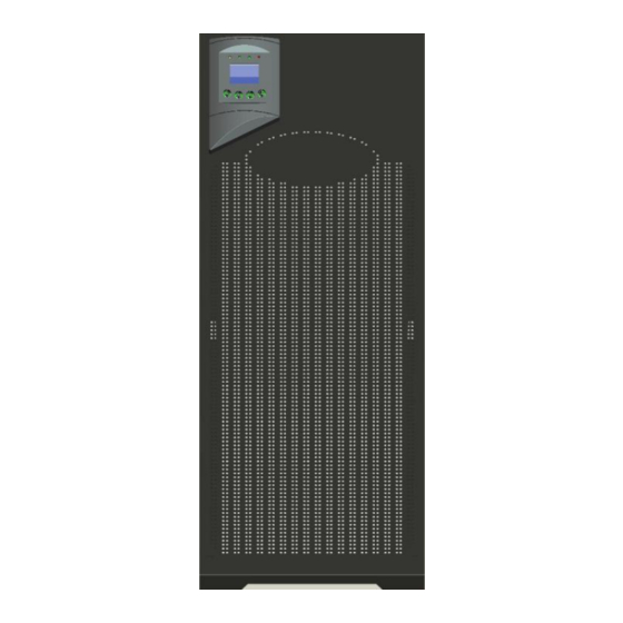
Seite 7: Abbildung 1: Xanto S 10000 3/1Bzw. Xanto S 20000 3/1
E I N L E I T U N G Hot-Swap Batterie Wirkungsgrad von bis zu 98% dank Hocheffizienzbetrieb RS-232- und USB-Schnittstelle Slot für optionale SNMP-Adapter Slot für optionale AS400- oder Relais-Karte Notaus-Funktion (REPO = Remote Emergency Power-Off) ... -
Seite 8: Sicherheitswarnungen
S I C H E R H E I T S W A R N U N G E N Sicherheitswarnungen Dieses Handbuch enthält wichtige Anweisungen, die Sie während der Installation und Wartung der USV-Anlage und der Batterien be- folgen müssen. Bitte lesen Sie alle Anweisungen des Handbuches, bevor sie mit dem Gerät arbeiten. -
Seite 9: Montage
M O N T A G E Montage Überprüfung der Lieferung Bewahren Sie die Transportkartons und das Verpackungsmaterial für die Spedition oder die Verkaufsstelle auf. Falls Anlagenteile wäh- rend des Transports beschädigt wurden, reichen Sie innerhalb von 24 Stunden eine Transportschaden-Reklamation bei Ihrem Lieferan- ten ein. -
Seite 10: Abbildung 2: Äußere Verpackung
M O N T A G E Abbildung 2: Äußere Verpackung 3. Entfernen Sie die Schaumteile und die Rampe. Nehmen Sie die Zubehörteile heraus (siehe Abbildung 3 links). Abbildung 3: Innere Verpackung 4. Lösen Sie die vier Schrauben (Gabelschlüssel 13mm) mit denen die USV-Anlage an der Unterseite an der Palette festgeschraubt ist. -
Seite 11: Überprüfung Des Zubehörs
M O N T A G E Überprüfung des Zubehörs Der Lieferumfang ist folgender Tabelle zu entnehmen: USV-Anlage Batteriepaket XANTO S XANTO S Batteriepaket XANTO Beschreibung 10000 3/1 20000 3/1 S 10000 / 20000 3/1 RS-232 Schnittstellenkabel Parallelkabel Abdeckung Parallel-Anschluss Halterung Parallel-Anschluss Drahtbrücke Software DataWatch... -
Seite 12: Elektrische Installation
Garantieanspruch verloren geht Der Anschluss der USV-Anlage an die Versorgungsspan- nung muss durch eine Elektrofachkraft erfolgen 3.5.1 Kabelquerschnitte XANTO S 10000 3/1 XANTO S 20000 3/1 Eingang / Main 1 2,5mm - 4mm - 10mm Bypass / Main 2... -
Seite 13: Klemmleiste
M O N T A G E 3.5.2 Klemmleiste Lösen Sie bitte die die 4 Schrauben an der Klemmenabdeckung für den Zugriff auf die Klemmleiste (siehe Abbildung 5). Abbildung 5: Klemmenabdeckung Unterhalb der Klemmenabdeckung sind vier Aussparungen für Ka- beldurchführungs-Verschraubungen vorgesehen, 3x 32mm Ø und 1x 40mm Ø. -
Seite 14: Anschließen Des Externen Batteriepakets
Sie das Flachbandkabel vom Display der Frontblende (siehe Abbildung 7). Abbildung 7: Entfernen der Frontblende der USV-Anlage 2. Trennen Sie die internen Batterieeinschübe (siehe Abbildung 8). XANTO S 10000 3/1 XANTO S 20000 3/1 Abbildung 8: Trennen der internen Batterieeinschübe 14 / 192 XS10000+XS20000_31_manual_ger_eng_it_V1.0.3.doc... -
Seite 15: Inbetriebnahme
M O N T A G E 3. Öffnen Sie die Sicherungen am Batteriepaket (siehe Abbildung Abbildung 9: Öffnen der Sicherungen am Batteriepaket 4. Verbinden Sie die Klemmleiste des externen Batteriepakets mit der Klemmleiste der USV-Anlage über das mitgelieferte Batteriekabel. 5. - Seite 16 Deaktivieren Sie den Notaus-Schalter und starten Sie die USV- Anlage neu. HINWEIS Die internen Batterien der XANTO S 10000 3/1 (XANTO S 20000 3/1) lassen sich in drei (fünf) Stunden auf 90% ihrer Kapazität aufladen. ONLINE empfiehlt, die Batterien nach der Installation oder nach einer längeren Lagerung 48 Stun-...
-
Seite 17: Betrieb
B E T R I E B Betrieb Funktionen auf dem Display Die USV-Anlage verfügt über ein Be- dienfeld mit vier Tasten, ein grafisches Display und vier Status-LED´s (siehe Abbildung 10). Im Normalbetrieb ist die Schrift weiß und die Hintergrund- beleuchtung blau. - Seite 18 B E T R I E B Status Grün Gelb Gelb △ △ △ △ Einschalten ● ↑ Normalbetrieb ● ● ↑ Batteriebetrieb ● ● ↑ Hocheffizienzbetrieb ● ↑ Bypassbetrieb ↑ ★ Standbybetrieb △ △ △ △ Batterietest ↑ ↑ ↑...
-
Seite 19: Startbildschirm
B E T R I E B USV-Anlagen Status Akustisches Alarmsignal Fehlermeldung Dauerhaft Warnmeldung 1x jede Sekunde Überlast 2x jede Sekunde Batteriebetrieb 1x alle 4 Sekunden, bei schwacher Batterie 1 x jede Sek. Bypassbetrieb 1x alle 2 Minuten Tabelle 5: Akustische Alarmsignale Startbildschirm Auf dem Startbildschirm sind alle wichtigen Daten auf einen Blick verfügbar. -
Seite 20: Hauptmenü
B E T R I E B Hauptmenü Hauptmenu Anzeigeinformation der Menüfunktion Untermenü USV-Status - Statusinformation - Warn- / Fehlermeldungen (sofern vorhanden) - Batteriestatus (Status und Ladestand) - Betriebsart u. Betriebszeit Ereignis- Zeigt bis zu 30 Warn- / Fehlermeldungen und protokoll Ereignisse an. -
Seite 21: Menü Einstellungen
B E T R I E B 4.3.1 Menü Einstellungen ACHTUNG Durch falsche Einstellungen können Sie den Stromversor- gungsschutz ausschalten oder sogar die angeschlossenen Verbraucher, die USV-Anlage oder die Batterien beschädi- gen. Beachten Sie die Empfehlungen bei den Einstellungen. Bei Fragen wenden Sie sich an den Support. HINWEIS Im Bypassbetrieb sind alle Einstellungen zugänglich. - Seite 22 B E T R I E B „Aktiviert“, „Deaktiviert“ „Aktiviert“ Automatischer Bypass Empfehlung: nicht ändern. „Aktiviert“, „Deaktiviert“ „Deaktiviert“ Kurzschluss <4s kein Alarm Bei Kurzschluss <4s am Ausgang wird bei „Aktiviert“ keine Warnmeldung erzeugt. Empfehlung: nicht ändern. 120V, …. 215V Bypassspannung 184V unteres Limit Empfehlung: nicht ändern.
-
Seite 23: Betriebszustände
B E T R I E B Betriebszustände Normalbetrieb Die USV-Anlage läuft im Normalbe- trieb (Online), das Versorgungsnetz ist vorhanden. Die USV-Anlage überwacht die Batte- rien und lädt diese je nach Bedarf auf. Zudem bietet sie den am Ausgang USV-Anlage angeschlossenen Abbildung 12: Normalbetrieb Geräten Stromversorgungsschutz. -
Seite 24: Abbildung 15: Standbybetrieb
B E T R I E B HINWEIS Bei Überlast schaltet sich die USV-Anlage nach einer vorge- gebenen Verzögerungszeit automatisch ab (siehe „Tabelle Elektrische Ausgangsleistung“ unter Technische Daten). Standbybetrieb Die USV-Anlage läuft im Standbybet- rieb. Die angeschlossene Last wird nicht mit Strom versorgt. -
Seite 25: Abbildung 19: Fehlermeldung
B E T R I E B Fehlermeldung Die USV-Anlage zeigt eine Fehler- meldung an. Ein akustisches Signal ertönt dauerhaft. Das Display wird rot. Schalten Sie die USV-Anlage aus. Wenden Sie sich an den Support. Abbildung 19: Fehlermeldung Überlast Die USV-Anlage zeigt eine Überlast an (siehe Technische Daten). -
Seite 26: Starten Und Abschalten Der Usv-Anlage
B E T R I E B Starten und Abschalten der USV-Anlage HINWEIS Überprüfen Sie vor dem Starten der USV-Anlage, ob alle Verbraucher ausgeschaltet sind. Schalten Sie nach dem Starten der USV-Anlage die Verbraucher der Reihe nach an. Schalten Sie vor dem Abschalten der USV-Anlage alle Ver- braucher aus. -
Seite 27: Abschalten Der Usv-Anlage Mit Versorgungsnetz
B E T R I E B 4.5.3 Abschalten der USV-Anlage mit Versorgungsnetz 1. Drücken Sie die Taste an der USV-Anlage drei Sekunden lang. Ein akustisches Signal von drei Sekunden Dauer ertönt. Die USV-Anlage wechselt in den Bypassbetrieb. HINWEIS Wird die Taste nach weniger als drei Sekunden losgelas- sen, so bleibt die USV-Anlage im Normalbetrieb. -
Seite 28: Konfigurieren Des Hocheffizienzbetriebs
B E T R I E B Konfigurieren des Hocheffizienzbetriebs In der Betriebsart Hocheffizienz wird ein Wirkungsgrad von bis zu 97% erreicht. Die USV-Anlage arbeitet normalerweise im Bypassbet- rieb, wechselt bei Ausfall des Netzes in weniger als 10ms zum Batte- riebetrieb und wechselt eine Minute nach Rückkehr des Netzstroms wieder in den Bypassbetrieb. -
Seite 29: Konfigurieren Der Bypass-Einstellungen
B E T R I E B Konfigurieren der Bypass-Einstellungen Automatischer Bypass: Standardmäßig wird ein Wechsel in den Bypassbetrieb erzwungen, wenn eine Überlast auftritt. Sie können die Einstellung deaktivieren. 1. Drücken Sie die Taste mindestens eine Sekunde lang, um die Menüoptionen zu aktivieren. Wählen Sie „EINSTEL- LUNGEN“... -
Seite 30: Konfigurieren Der Batterieeinstellungen
B E T R I E B Konfigurieren der Batterieeinstellungen 4.8.1 Externe Batteriepakete Konfigurieren Sie die USV-Anlage für externe Batteriepakete, um ei- ne maximale Batterielaufzeit zu gewährleisten: 1. Drücken Sie die Taste mindestens eine Sekunde lang, um die Menüoptionen zu aktivieren. Wählen Sie „EINSTEL- LUNGEN“... -
Seite 31: Konfigurieren Des Automatische Neustarts
B E T R I E B Voraussetzungen für den automatischen Batterietest: Die Einstellung „Automatische Batterietests“ darf nicht auf null stehen Die Batterien müssen vollständig aufgeladen sein (100%) Die USV-Anlage läuft im Normalzustand, es liegt keine Warn- / Fehlermeldung vor ... -
Seite 32: Spezial-Funktionen
S P E Z I A L - F U N K T I O N E N Spezial-Funktionen Redundanz- / Parallelbetrieb Die USV-Systeme XANTO S 10000 3/1 und XANTO S 20000 3/1 ermöglichen einen gemischten Redundanz- / Parallelbetrieb als zu- verlässiger N+X Verbund. N steht für die minimale Zahl der paralle- len USV-Anlagen die die Last benötigt. -
Seite 33: Ist Die Brücke Zwischen Jp1 Und Jp2 Am Klemmenanschluss
S P E Z I A L - F U N K T I O N E N 4. Ist die Brücke zwischen JP1 und JP2 am Klemmenanschluss eingelegt, so entfernen Sie diese bei jeder USV-Anlage (siehe Abbildung 6) Die Brücke ist nur für den Einzelbetrieb notwen- dig. -
Seite 34: Abbildung 24: Anschlussplan 2 Redundanz-/Parallelbetrieb
S P E Z I A L - F U N K T I O N E N Versorgungsspannung Supply Voltage Wartungs-Bypass für Redundanz- / Parallelbetrieb Maintenance Bypass for redundancy / parallel mode USV 1 USV 2 USV 3 USV 4 UPS 1 UPS 2 UPS 3... -
Seite 35: Inbetriebnahme Redundanz- / Parallelbetrieb
S P E Z I A L - F U N K T I O N E N 5.1.2 Inbetriebnahme Redundanz- / Parallelbetrieb HINWEIS Hocheffizienzbetrieb ist nicht verfügbar, bitte deaktivieren (siehe Menü Einstellungen) Weitere Einstellungen müssen nicht vorgenommen werden ... -
Seite 36: Wechseln Der Betriebsart Der Usv-Anlagen
S P E Z I A L - F U N K T I O N E N 5.1.3 Wechseln der Betriebsart der USV-Anlagen Vom Normal- zum Bypassbetrieb: Drücken Sie die Taste an ei- ner USV-Anlage drei Sekunden lang. Alle USV-Anlagen wechseln die Betriebsart. -
Seite 37: Rückspeiseschutz (Backfeed Protection)
USV-Anlage. Zusätzlich wird die Fehlermeldung „Alarm Rückleis- tung“ im Display der USV-Anlage angezeigt. Für den Rückspeiseschutz muss ein zusätzliches Schütz installiert werden (siehe Abbildung 25). Das Schütz muss mindestens 60A (XANTO S 10000 3/1) bzw. 125A (XANTO S 20000 3/1) schalten können. Bypass Bypass... -
Seite 38: Kommunikation
Intelligent Slot AS400 Slot AS400 Slot Wartungsbypass Lüfter Maintenance Switch Rückspeiseschutz- Anschluss Backfeed Protection Port Eingangsschalter Input Breaker Main 1 / Main 2 Klemmenabdeckung Terminal Blocks Cover Abbildung 26: Kommunikationsoptionen XANTO S 10000 3/1 38 / 192 XS10000+XS20000_31_manual_ger_eng_it_V1.0.3.doc R. Kistler... -
Seite 39: Kommunikationsoptionen
K O M M U N I K A T I O N Kommunikationsoptionen Die XANTO S verfügt über eine serielle (RS-232) - und eine USB - Kommunikationsschnittstelle sowie zwei Slots für optionale Schnitt- stellenkarten. HINWEIS Die Datenübertragungsgeschwindigkeit der USB-Schnitt- stelle (USB 1.1) ist auf 2400 Baud festgelegt. -
Seite 40: Slots Für Schnittstellenkarten
K O M M U N I K A T I O N Nummer des Signal Funktion Anschlussstiftes Übertragung an ein externes Gerät Empfang von externem Gerät Masse (mit dem Maschinengestell verbunden) Tabelle 9: Anschlussstiftbelegung der RS-232 6.1.2 Slots für Schnittstellenkarten Die XANTO S ist mit zwei Slots (siehe Abbildung 26) für die folgen- den Schnittstellenkarten ausgestattet: Intelligent Slot... -
Seite 41: Notaus-Funktion (Repo)
K O M M U N I K A T I O N 6.1.3 Notaus-Funktion (REPO) Die Notaus-Funktion (REPO = Remote Emergency Power-Off) dient zum Herunterfahren der USV-Anlage und zum sofortigen Abschalten der angeschlossenen Verbraucher aus der Ferne. Hierzu muss der REPO-Stecker (Rückseite USV-Anlage) entfernt und ein externer Notaus-Schalter angeschlossen werden. -
Seite 42: Datawatch Software
K O M M U N I K A T I O N DataWatch Software Zum serienmäßigen Lieferumfang der XANTO S-Serie gehört Data- Watch, die umfassende Softwarelösung zum Shutdown und Mana- gement des PC- oder Serversystems, sowie zum Monitoring der XANTO S und des Stromversorgungsnetzes. -
Seite 43: Wartung
W A R T U N G Wartung Pflege und Wartung von USV-Anlagen / Batte- rien Für eine lange Lebensdauer der Anlage sollte der Bereich um die USV sauber und staubfrei sein. Falls es in der Umgebung der Anla- ge sehr staubig ist, reinigen Sie die Außenflächen der Anlage mit ei- nem Staubsauger. -
Seite 44: Wartungsbetrieb
W A R T U N G Wartungsbetrieb ACHTUNG Wartungsarbeiten sollten durch einen qualifizierten Techni- ker durchgeführt werden, der mit USV-Anlagen und den nö- tigen Sicherheitsvorkehrungen vertraut ist. Halten Sie unbe- fugtes Personal von der USV-Anlage fern. Der Wartungsbetrieb wird für Servicearbeiten an der USV-Anlage benötigt, wenn dabei die Last weiterhin versorgt werden muss, z.B. -
Seite 45: Lagerung Von Usv-Anlagen / Batterien
W A R T U N G Lagerung von USV-Anlagen / Batterien Falls Sie die USV-Anlage über längere Zeit lagern, laden Sie die Bat- terie alle sechs Monate auf, indem Sie die USV-Anlage an das Ver- sorgungsnetz anschließen. Die internen Batterien laden sich in we- niger als drei Stunden auf bis zu 90% ihrer Kapazität auf. - Seite 46 W A R T U N G ACHTUNG Wartungsarbeiten sollten durch einen qualifizierten Techni- ker durchgeführt werden, der mit Batterien und den nötigen Sicherheitsvorkehrungen vertraut ist. Halten Sie unbefugtes Personal von den Batterien fern Die internen Batterien der USV haben ein hohes Gewicht. Beim Umgang mit den schweren Batterien ist Vorsicht gebo- ...
-
Seite 47: Abbildung 28: Entfernen Der Frontblende Der Usv-Anlage
W A R T U N G 1. Entfernen Sie die Frontblende von der USV-Anlage / des Bat- teriepakets und lösen Sie bei der USV-Anlage das Flachband- kabel vom Display der Frontblende (siehe Abbildung 28). Abbildung 28: Entfernen der Frontblende der USV-Anlage 2. - Seite 48 W A R T U N G 4. Tauschen Sie die Batterien im Batterieeinschub aus. Lesen Sie den Abschnitt „Entsorgen der Altbatterien oder der USV- Anlage“ für eine sachgemäße Entsorgung. 5. Schieben Sie den Batterieeinschub mit den neuen Batterien in das Gehäuse.
-
Seite 49: Testen Der Neuen Batterien
W A R T U N G Testen der neuen Batterien 1. Drücken Sie die Taste mindestens eine Sekunde lang, um die Menüoptionen zu aktivieren. Wechseln Sie ins Menü „KONTROLLE“ und anschließend zu „BATTERIETEST“. 2. Drücken Sie die Taste, um den Batterietest zu starten. HINWEIS Voraussetzungen für den Batterietest: ... -
Seite 50: Fehlerbehebung
F E H L E R B E H E B U N G Fehlerbehebung Die XANTO S ist für den selbständigen Betrieb ausgelegt und meldet etwaige auftretende Probleme beim Betrieb automatisch. Normaler- weise bedeuten die auf dem Bedienfeld angezeigten Warnmeldun- gen nicht, dass die Ausgangsspannung betroffen ist. -
Seite 51: Warn- Und Fehlermeldungen
F E H L E R B E H E B U N G Warn- und Fehlermeldungen Prüfen Sie den Status der Warn- und Fehlermeldungen anhand fol- gender Tabelle. Führen Sie geeignete Maßnahmen durch, um die- sen Zustand zu beheben. Warn- bzw. - Seite 52 F E H L E R B E H E B U N G Warn- bzw. Mögliche Ursache Maßnahme Fehlermeldung 41 Warnung Der Energiebedarf über- Verringern Sie die Last an der USV- Ausgang Überlast schreitet die Kapazität Anlage. Der USV-Betrieb wird fortge- der USV-Anlage im setzt, die USV-Anlage kann in den 42 Fehler...
- Seite 53 F E H L E R B E H E B U N G Warn- bzw. Mögliche Ursache Maßnahme Fehlermeldung Spezifische Warn- / Fehlermeldungen bei Parallelschaltung. E2 Fehler Parallelkabel fehlerhaft Überprüfen Sie das Parallelkabel auf Parallelkabel Fehler korrekten Steckkontakt. E3 Warnung Parallelkabel fehlerhaft Überprüfen Sie das Parallelkabel auf Parallelkabel Fehler...
-
Seite 54: Sonstige Fehlerursachen
F E H L E R B E H E B U N G Sonstige Fehlerursachen Sonstige Fehler Mögliche Ursache Maßnahme Die USV stellt nicht Die Batterien müssen Schließen Sie die USV-Anlage 48 die erwartete Zeit aufgeladen oder Stunden lang an den Netzstrom an, für die Datensiche- tauscht werden. -
Seite 55: Stummschalten Des Alarmsignals
F E H L E R B E H E B U N G Stummschalten des Alarmsignals 1. Drücken Sie die Taste mindestens eine Sekunde lang, um die Menüoptionen zu aktivieren. Wechseln Sie ins Menü „KONTROLLE“ und anschließend zu „ALARM LAUTLOS“. 2. -
Seite 56: Technische Daten
Technische Daten Spezifikationen der USV-Anlagen 9.1.1 Liste der Gerätetypen USV-Anlage Artikel-Nr. Leistung Batteriepaket Artikel-Nr. 10000 VA Batteriepaket XANTO S 10000 3/1 XST1000031 9000 W XANTO S XST1000031BP 10000 / 20000 VA XANTO S 20000 3/1 XST2000031 20000 3/1 18000 W Tabelle 14: Liste USV-Anlagen und Batteriepakete 9.1.2... - Seite 57 T E C H N I S C H E D A T E N Modell Eingangsanschluss Ausgangsanschlüsse XANTO S 10000 3/1 Klemmenanschluss Klemmenanschluss XANTO S 20000 3/1 Klemmenanschluss Klemmenanschluss Tabelle 18: Elektrische Ein- und Ausgangsanschlüsse Wirkungsgrad >97% Hocheffizienzbetrieb >93% Normalbetrieb >92% Batteriebetrieb...
-
Seite 58: Batterie
9.1.4 Batterie Interne Batterie Batteriepaket (BP) Siche- rung XANTO S 10000 3/1 288V (24 x 12V / 9Ah) 1 Reihe parallel 288V (48 x 12V / 9Ah) 2 Reihen parallel XANTO S 20000 3/1 288V (48 x 12V / 9Ah) 2 Reihen parallel Ausführung... -
Seite 59: Umwelt Und Sicherheit
T E C H N I S C H E D A T E N 9.1.7 Umwelt und Sicherheit Überspannungsschutz EN 61000-4-2, Ebene 4 EN 61000-4-3, Ebene 3 EN 61000-4-4, Ebene 4 EN 61000-4-5, Ebene 4 EMV-Zertifikate CE gemäß IEC/EN 62040-2 Kategorie C3 Sicherheit IEC 62040-1-1 Zulassung... -
Seite 60: Rückansichten Der Usv-Anlagen
T E C H N I S C H E D A T E N Rückansichten der USV-Anlagen Beschreibung der Anschlüsse siehe Kommunikation. Abbildung 30: Rückseiten XANTO S 10000 3/1 und 20000 3/1 60 / 192 XS10000+XS20000_31_manual_ger_eng_it_V1.0.3.doc R. Kistler... -
Seite 61: Ce Bestätigung
T E C H N I S C H E D A T E N CE Bestätigung 61 / 192 XS10000+XS20000_31_manual_ger_eng_it_V1.0.3.doc R. Kistler... -
Seite 62: Garantie
G A R A N T I E Garantie Die ONLINE USV-Systeme AG (ONLINE) gewährleistet, dass dieses Produkt für die Dauer von zwei Jahren ab Kaufdatum frei von Mate- rial- und Fertigungsfehlern ist. Die Verpflichtung von ONLINE gemäß dieser Garantie ist auf die Reparatur oder den Ersatz (Entscheidung trifft ONLINE) jeglicher defekter Produkte begrenzt. - Seite 63 63 / 192 XS10000+XS20000_31_manual_ger_eng_it_V1.0.3.doc R. Kistler...
- Seite 64 64 / 192 XS10000+XS20000_31_manual_ger_eng_it_V1.0.3.doc R. Kistler...
-
Seite 65: User Manual
Page English: Page 65 - 128 Italia: Pagina 129 - 192 Germany Italy Switzerland ONLINE USV-Systeme AG ONLINE UPS-Systems S.r.l. ONLINE USV-Systeme AG Dreimühlenstraße 4 Via Edison 12 Eigenheimstraße 11 D-80469 Munich I-20852 Villasanta (MB) CH-8304 Wallisellen (Zürich) Phone +49 (89) 2423990-10... - Seite 66 66 / 192 XS10000+XS20000_31_manual_ger_eng_it_V1.0.3.doc R. Kistler...
- Seite 67 Contents User Manual ..................65 Introduction ................70 Safety warnings ................ 72 Installation ................73 Inspecting the shipment ............ 73 Unpacking the UPS system ..........73 Checking the accessories ..........75 Mechanical installation ............75 Electrical installation ............76 3.5.1 Cable cross-section ............76 3.5.2 Terminal strip ..............
- Seite 68 Special functions ..............96 Redundancy/parallel operation ......... 96 5.1.1 Electrical installation redundant/parallel operation .... 96 5.1.2 Commissioning redundant/parallel operation ....99 5.1.3 Switching the operating mode of the UPS systems ..100 Converter mode............... 100 Backfeed protection ............101 Communication ............... 102 Communication options ...........
- Seite 69 List of figures Figure 1: XANTO S 10000 3/1 resp. XANTO S 20000 3/1 ....71 Figure 2: Outer packaging ..............74 Figure 3: Inner packaging ..............74 Figure 4: Floor attachment..............76 Figure 5: Terminal cover ..............77 Figure 6: Terminal strip ............... 77 Figure 7: Removing the front cover of the UPS system .....
-
Seite 70: Introduction
I N T R O D U C T I O N Introduction ONLINE USV-Systeme AG (ONLINE) is one of the leading manufac- turers of Uninterruptible Power Supplies (UPS). Since 1988, the German company has specialised in the development, manufacture and sales &... -
Seite 71: Figure 1: Xanto S 10000 3/1 Resp. Xanto S 20000 3/1
Slot for optional SNMP adapter Slot for optional AS400 or relay card Emergency-off function (REPO = Remote Emergency Power- Off) Maintenance Switch Figure 1: XANTO S 10000 3/1 resp. XANTO S 20000 3/1 71 / 192 XS10000+XS20000_31_manual_ger_eng_it_V1.0.3.doc R. Kistler... -
Seite 72: Safety Warnings
S A F E T Y W A R N I N G S Safety warnings This handbook contains important instructions that you must comply with during the installation and maintenance of the UPS system and the batteries. Please read these instructions completely before you begin working with the device. -
Seite 73: Installation
I N S T A L L A T I O N Installation Inspecting the shipment Keep the shipping cartons and the packaging material for the ship- ping company or the sales agency. If parts of the system were dam- aged during transport, please submit a transport damage claim to your supplier within 24 hours. -
Seite 74: Figure 2: Outer Packaging
I N S T A L L A T I O N Figure 2: Outer packaging 8. Remove the foam pieces and the ramp. Take out the acces- sory parts (see Figure 3 left). Figure 3: Inner packaging 9. Unscrew the four bolts (13 mm open-end wrench) which secure the UPS system at the bottom side to the pallet. -
Seite 75: Checking The Accessories
I N S T A L L A T I O N Checking the accessories Refer to the following table for the scope of supply: UPS system Battery module XANTO S XANTO S Battery module XANTO Description 10000 3/1 20000 3/1 S 10000 / 20000 3/1 RS-232 interface cable Parallel cable... -
Seite 76: Electrical Installation
Only qualified electricians may connect the UPS system to the power supply 3.5.1 Cable cross-section XANTO S 10000 3/1 XANTO S 20000 3/1 Line input / Main 1 2.5 mm - 4 mm 6 mm - 10 mm... -
Seite 77: Terminal Strip
I N S T A L L A T I O N 3.5.2 Terminal strip Please unscrew the four screws at the terminal cover for access to the terminal strip (see Figure 5). Figure 5: Terminal cover Below the terminal cover are four openings for cable gland fittings, 3x 32 mm Ø... -
Seite 78: Connecting The External Battery Module
(see Figure 7). Figure 7: Removing the front cover of the UPS system 10. Disconnect the internal battery module inserts (see Figure 8). XANTO S 10000 3/1 XANTO S 20000 3/1 Figure 8: Disconnecting the internal battery module inserts 78 / 192 XS10000+XS20000_31_manual_ger_eng_it_V1.0.3.doc... -
Seite 79: Commissioning
I N S T A L L A T I O N 11. Open the fuses on the battery module (see Figure 9) Figure 9: Opening the fuses on the battery module 12. Connect the terminal strip of the external battery module with the terminal strip of the UPS system using the supplied battery cable. - Seite 80 Deactivate the emergency-off switch and restart the UPS system. NOTE The internal batteries of the XANTO S 10000 3/1 (XANTO S 20000 3/1) can be charged to 90% of their capacity in three (five) hours. ONLINE recommends charging the batter- ies for 48 hours after installation or after a longer period of storage.
-
Seite 81: Operation
O P E R A T I O N Operation Functions on the display The UPS system has a control panel with four buttons, a graphical display and four status LEDs (see Figure 10). In normal mode, the text is white and the background illumination is blue. - Seite 82 O P E R A T I O N Status Green Yellow Yellow △ △ △ △ Switch on ● ↑ Normal mode ● ● ↑ Battery mode ● ● ↑ ECO mode ● ↑ Bypass mode ↑ ★ Standby mode △...
-
Seite 83: Start Screen
O P E R A T I O N UPS systems status Audio alarm signal Error message Continuous Warning message 1x per second Overload 2x per second Battery mode 1x every 4 seconds, for weak battery 1x every second. Bypass mode 1x every 2 minutes Table 5: Audio alarm signals Start screen... -
Seite 84: Main Menu
O P E R A T I O N Main menu Main menu Display information of the menu function Submenu UPS status - Status information - Warning/error messages (if existing) - Battery status (status and charging status) - Operating mode and running time Event log Displays up to 30 warning/error messages and events. -
Seite 85: Settings Menu
O P E R A T I O N 4.3.1 Settings menu CAUTION Incorrect settings can cause you to inadvertently switch off the power supply protection or even damage the connected consumers, the UPS system or the batteries. Observe the recommendations for the settings. - Seite 86 O P E R A T I O N Automatic bypass "Enabled", "Disabled" "Enabled" Recommendation: Do not change. Short circuit <4s "Enabled", "Disabled" "Disabled" no alarm In the event of a short circuit <4s on the out- put, no warning messages are generated for "Enabled".
-
Seite 87: Operating States
O P E R A T I O N Operating states Normal mode The UPS system is running in normal mode (online), the mains power supply is available. The UPS system monitors the batteries and charges these as needed. The bat- teries also provide power supply protec- tion to the devices connected to the Figure 12: Normal mode... -
Seite 88: Figure 15: Standby Mode
O P E R A T I O N NOTE In the event of an overload, the UPS system will automatical- ly switch off after a prespecified time delay (see "Electrical output power table" under Technical Data). Standby mode The UPS system is running in standby mode. -
Seite 89: Figure 19: Error Message
O P E R A T I O N Error message The UPS system is displaying an error message. An audio signal is emitted continuously. The display turns red. Switch off the UPS system. Please contact support. Figure 19: Error message Overload The UPS system is displaying an overload (see Technical Data). -
Seite 90: Starting And Switching Off The Ups System
O P E R A T I O N Starting and switching off the UPS system NOTE Before starting the UPS system, check whether all consum- ers are switched off. After starting the UPS system, switch on the consumers one after the other. ... -
Seite 91: Switching Off The Ups System With Mains Power Supply
O P E R A T I O N 4.5.3 Switching off the UPS system with mains power supply 4. Press the button on the UPS system for 3 seconds. An audio signal is emitted for 3 seconds. The UPS system switches to bypass mode. -
Seite 92: Configuring The Eco Mode
O P E R A T I O N Configuring the ECO mode In the high-efficiency mode, an efficiency of up to 97% is achieved. The UPS system normally works in bypass mode. It will switch to battery mode in less than 10 ms if the mains power fails and will switch back to bypass mode 1 minute after the mains power has returned. -
Seite 93: Configuring The Bypass Settings
O P E R A T I O N Configuring the bypass settings Automatic bypass: By default, a switch to the bypass mode will be forced if an overload occurs. You can disable the setting. 4. Press the button for at least one second to enable the menu options. -
Seite 94: Configuring The Battery Settings
O P E R A T I O N Configuring the battery settings 4.8.1 External battery modules Configure the UPS system for external battery modules to ensure a maximum battery runtime: 5. Press the button for at least one second to enable the menu options. -
Seite 95: Configuring The Automatic Restart
O P E R A T I O N Requirements for the automatic battery test: The "Automatic battery tests" setting may not be set to zero The batteries must be fully charged (100%) The UPS system is running in normal mode and there are no warning/error messages present ... -
Seite 96: Special Functions
S P E C I A L F U N C T I O N S Special functions Redundancy/parallel operation The UPS systems XANTO S 10000 3/1 and XANTO S 20000 3/1 facilitate a mixed redundancy/parallel operation as reliable N+X net- work. N stands for the minimum number of parallel UPS systems which the load requires. -
Seite 97: Figure 23: Connection Diagram 1 Redundant/Parallel Operation
S P E C I A L F U N C T I O N S 9. If the jumper between JP1 and JP2 on the terminal connection is inserted, then remove this for each UPS system (see Figure 6); the jumper is only necessary for individual mode. 10. -
Seite 98: Figure 24: Connection Diagram 2 Redundant/Parallel Operation
S P E C I A L F U N C T I O N S Versorgungsspannung Supply Voltage Wartungs-Bypass für Redundanz- / Parallelbetrieb Maintenance Bypass for redundancy / parallel mode USV 1 USV 2 USV 3 USV 4 UPS 1 UPS 2 UPS 3 UPS 4... -
Seite 99: Commissioning Redundant/Parallel Operation
S P E C I A L F U N C T I O N S 5.1.2 Commissioning redundant/parallel operation NOTE ECO mode is not available, please disable (see Settings menu) Additional settings must not be made This chapter discusses the the main features of the parallel operation and additionally refers to the Commissioning section... -
Seite 100: Switching The Operating Mode Of The Ups Systems
S P E C I A L F U N C T I O N S 5.1.3 Switching the operating mode of the UPS systems From normal to bypass mode: Press the button on one of the UPS systems for 3 seconds. All UPS systems switch to the operating mode. -
Seite 101: Backfeed Protection
"Backfeed alarm" is shown in the display of the UPS system. An additional contactor must be installed for the backfeed protection (see Figure 25). The contactor must be able to switch at least 60A (XANTO S 10000 3/1) resp. 125A (XANTO S 20000 3/1). Bypass Bypass... -
Seite 102: Communication
AS400 Slot Maintenance Switch Maintenance Switch Backfeed Protection Port Backfeed Protection Port Input Breaker Input Breaker Main 1 / Main 2 Terminal Blocks Cover Terminal Blocks Cover Figure 26: Communication options XANTO S 10000 3/1 102 / 192 XS10000+XS20000_31_manual_ger_eng_it_V1.0.3.doc R. Kistler... -
Seite 103: Communication Options
C O M M U N I C A T I O N Communication options The XANTO S features a serial (RS-232) and a USB communica- tions port as well as two slots for optional interface cards. NOTE The data transfer rate of the USB interface (USB 1.1) is set to 2400 baud. -
Seite 104: Slots For Interface Cards
C O M M U N I C A T I O N Number of the Signal Function connection pin Transmission to an external device Reception from external device Ground (connected to the machine frame) Table 9: Connection assignment of the RS-232 6.1.2 Slots for interface cards The XANTO S is equipped with two slots (see Figure 26) for the fol-... -
Seite 105: Emergency-Off Function (Repo)
C O M M U N I C A T I O N 6.1.3 Emergency-off function (REPO) The emergency-off function (REPO = Remote Emergency Power- Off) serves to shut down the UPS system and to immediately switch off the connected consumers remotely. The REPO connector (rear side of the UPS system) must be removed and an external emer- gency-off switch must be connected for this. -
Seite 106: Datawatch Software
C O M M U N I C A T I O N DataWatch software The XANTO S series includes DataWatch, the comprehensive soft- ware solution for the shutdown and management of the PC or server system, as well as monitoring the XANTO S and the mains power supply. -
Seite 107: Maintenance
M A I N T E N A N C E Maintenance Care and maintenance of UPS sys- tems/batteries To ensure a long service life of the system, the area around the UPS system should be kept clean and free of dust. If the area around the system is very dusty, clean the outer surfaces of the system using a vacuum cleaner. -
Seite 108: Maintenance Mode
M A I N T E N A N C E Maintenance mode CAUTION Maintenance work should be performed by a qualified tech- nician who is experienced in working with UPS systems and understands the necessary safety precautions. Keep unau- thorised personnel away from the UPS system. -
Seite 109: Storing Ups Systems/Batteries
M A I N T E N A N C E Storing UPS systems/batteries If you store the UPS system over a longer period of time, charge the batteries every six months by connecting the UPS system to the mains power supply. The internal batteries will charge up to 90% of their capacity in less than three hours. - Seite 110 M A I N T E N A N C E CAUTION Maintenance work should be performed by a qualified tech- nician who is experienced in working with batteries and un- derstands the necessary safety precautions. Keep unauthor- ised personnel away from batteries ...
-
Seite 111: Figure 28: Removing The Front Cover Of The Ups System
M A I N T E N A N C E Figure 28: Removing the front cover of the UPS system 11. Disconnect the internal battery plug connections of the individ- ual battery module inserts and remove the battery cover by releasing both upper screws (see Figure 29). - Seite 112 M A I N T E N A N C E 14. Insert the battery module insert with the new batteries into the housing. This requires some effort. 15. Insert the battery cover again. CAUTION A small spark can occur when the batteries are being connect- ed.
-
Seite 113: Testing The New Batteries
M A I N T E N A N C E Testing the new batteries 3. Press the button for at least one second to enable the menu options. Switch to the "CHECKS" menu and then to "BATTERY TEST". 4. Press the button to start the battery test. -
Seite 114: Troubleshooting
T R O U B L E S H O O T I N G Troubleshooting The XANTO S is designed for automatic operation and reports any occurring problems during operation automatically. Normally, the warning messages shown on the control panel do not mean that the output voltage is affected. -
Seite 115: Warning And Error Messages
T R O U B L E S H O O T I N G Warning and error messages Check the status of the warning and error messages using the fol- lowing table. Perform suitable measures to rectify this state. Warning or error Possible causes Measure... - Seite 116 T R O U B L E S H O O T I N G Warning or error Possible causes Measure message 41 Warning The energy demand ex- Reduce the load on the UPS Output Overload ceeds the capacity of the system.
- Seite 117 T R O U B L E S H O O T I N G Warning or error Possible causes Measure message Specific warning/error messages for parallel connection. E2 Fault Parallel Cable Faulty Check the parallel cable for cor- Parallel Cable Fault rect connector contact.
-
Seite 118: Other Fault Causes
T R O U B L E S H O O T I N G Other fault causes Other faults Possible causes Measure The UPS does not The batteries must be Connect the UPS system to the make the expected charged or replaced. -
Seite 119: Muting The Alarm Signal
T R O U B L E S H O O T I N G Muting the alarm signal 3. Press the button for at least one second to enable the menu options. Switch to the "CHECKS" menu and then to "BUZZER MUTE". -
Seite 120: Technical Data
List of the device types UPS system Article Power Battery Article number number module 10000 VA Battery module XANTO S 10000 3/1 XST1000031 9000 W XANTO S XST1000031BP 10000 / 20000 VA XANTO S 20000 3/1 XST2000031 20000 3/1 18000 W Table 14: List of the UPS systems and battery modules 9.1.2... - Seite 121 T E C H N I C A L D A T A Model Input connection Output connections XANTO S 10000 3/1 Terminal connection Terminal connection XANTO S 20000 3/1 Terminal connection Terminal connection Table 18: Electrical input and output connections Efficiency >97% ECO mode...
-
Seite 122: Battery
Battery Internal battery Battery module Fuse (BP) XANTO S 10000 3/1 288V (24 x 12 V / 9 Ah) 288V (48 x 12V / 9 1 row parallel XANTO S 20000 3/1 288V (48 x 12 V / 9 Ah) -
Seite 123: Environment And Safety
T E C H N I C A L D A T A 9.1.7 Environment and safety Overvoltage protection EN 61000-4-2, Level 4 EN 61000-4-3, Level 3 EN 61000-4-4, Level 4 EN 61000-4-5, Level 4 EMC Certificate CE according to IEC/EN 62040-2 Category C3 Safety IEC 62040-1-1 Approval... -
Seite 124: Back Views Of The Ups Systems
T E C H N I C A L D A T A Back views of the UPS systems Description of the connections, see Communication. Figure 30: Rear sides XANTO S 10000 3/1 and 20000 3/1 124 / 192 XS10000+XS20000_31_manual_ger_eng_it_V1.0.3.doc... -
Seite 125: Ce Conformity
T E C H N I C A L D A T A CE conformity 125 / 192 XS10000+XS20000_31_manual_ger_eng_it_V1.0.3.doc R. Kistler... -
Seite 126: Warranty
W A R R A N T Y Warranty ONLINE USV-Systeme AG (ONLINE) hereby warrants this product to be free from defects in material and workmanship for a period of two years from the date of purchase. The obligation of ONLINE under this warranty is limited to the replacement or repair of any product which proves upon our examination to be defective. - Seite 127 127 / 192 XS10000+XS20000_31_manual_ger_eng_it_V1.0.3.doc R. Kistler...
- Seite 128 128 / 192 XS10000+XS20000_31_manual_ger_eng_it_V1.0.3.doc R. Kistler...
-
Seite 129: Manuale Dell'utente
Seite English: Page 65 - 128 Italiano: Pagina 129 - 192 Germania Italia Svizzera ONLINE USV-Systeme AG ONLINE UPS-Systems S.r.l. ONLINE USV-Systeme AG Dreimühlenstraße 4 Via Edison 12 Eigenheimstraße 11 D-80469 München I-20852 Villasanta (MB) CH-8304 Wallisellen (Zürich) Phone +49 (89) 2423990-10... - Seite 130 130 / 192 XS10000+XS20000_31_manual_ger_eng_it_V1.0.3.doc R. Kistler...
- Seite 131 Indice Manuale dell'utente ................ 129 Introduzione ................134 Avvertenze di sicurezza ............136 Montaggio ................137 Controllo della fornitura ........... 137 Disimballaggio dell’UPS ..........137 Controllo degli accessori ..........139 Installazione meccanica ..........139 Installazione elettrica ............140 3.5.1 Sezioni del cavo .............. 140 3.5.2 Morsettiera ..............
- Seite 132 5.1.3 Commutazione della modalità d'esercizio degli UPS ..164 Modalità Convertitore di Frequenza ........ 164 Protezione da corrente di ritorno (Backfeed Protection) 165 Comunicazione ............... 166 Opzioni di comunicazione ..........167 6.1.1 Interfaccia di comunicazione RS-232 e USB ....167 6.1.2 Slot per schede d'interfaccia ...........
- Seite 133 Elenco delle figure Figura 1: XANTO S 10000 3/1 oppure XANTO S 20000 3/1 ... 135 Figura 2: Imballaggio esterno ............138 Figura 3: Imballaggio interno ............138 Figura 4: Fissaggio al pavimento ............140 Figura 5: Copertura morsetti ............. 141 Figura 6: Morsettiera .................
-
Seite 134: Introduzione
I N T R O D U Z I O N E Introduzione ONLINE USV-Systeme AG (ONLINE) è un'azienda tedesca leader nel settore dei gruppi di continuità (UPS), attiva dal 1988 nello sviluppo, produzione, commercializzazione e assistenza di UPS. L'azienda è al primo posto nel mercato tedesco dei gruppi di continuità... - Seite 135 Slot per scheda AS400 o scheda relè opzionale Funzione di arresto d'emergenza remoto (REPO = Remote Emergency Power-Off) Bypass di manutenzione Figura 1: XANTO S 10000 3/1 oppure XANTO S 20000 3/1 135 / 192 XS10000+XS20000_31_manual_ger_eng_it_V1.0.3.doc R. Kistler...
-
Seite 136: Avvertenze Di Sicurezza
A V V E R T E N Z E D I S I C U R E Z Z A Avvertenze di sicurezza Il presente manuale contiene istruzioni importanti da osservare du- rante l'installazione e la manutenzione dell’UPS e delle batterie. Pri- ma di lavorare con l'apparecchio, leggere attentamente tutte le istru- zioni del presente manuale. -
Seite 137: Montaggio
M O N T A G G I O Montaggio Controllo della fornitura Il cliente è tenuto al momento della consegna a premettere alla firma sul documento di consegna del trasportatore la dicitura “RITIRATO CON RISERVA DI VERIFICA”. In caso contrario, le compagnie assi- curative non accettano il rimborso della merce e di conseguenza ONLINE non potrà... - Seite 138 M O N T A G G I O Figura 2: Imballaggio esterno 3. Rimuovere le parti in polistirolo e la rampa. Prelevare gli accessori (vedi Figura 3 a sinistra). Figura 3: Imballaggio interno 4. Allentare le quattro viti (con una chiave fissa da 13 mm) che fissano il lato inferiore dell’UPS al pallet.
-
Seite 139: Controllo Degli Accessori
M O N T A G G I O Controllo degli accessori La dotazione della fornitura è riportata nella seguente tabella: Cabinet batterie Cabinet batterie XANTO XANTO XANTO S 10000 / Descrizione S 10000 3/1 S 20000 3/1 20000 3/1 Cavo d'interfaccia RS-232 Cavo parallelo Copertura porta parallela... -
Seite 140: Installazione Elettrica
Il collegamento dell’UPS alla tensione di alimentazione deve essere effettuato da un elettrotecnico qualificato 3.5.1 Sezioni del cavo XANTO S 10000 3/1 XANTO S 20000 3/1 Ingresso / Main 1 2,5 mm - 4 mm 6 mm... -
Seite 141: Morsettiera
M O N T A G G I O 3.5.2 Morsettiera Allentare le 4 viti sulla copertura dei morsetti per accedere alla mor- settiera (vedi Figura 5). Figura 5: Copertura morsetti Sotto la copertura dei morsetti sono previste quattro fessure per i passacavi a vite, 3 x 32 mm Ø... -
Seite 142: Collegamento Del Cabinet Batterie Esterno
(vedi Figura 7). Figura 7: Rimozione del pannello frontale dell’UPS 2. Scollegare gli inserti batterie interni (vedi Figura 8). XANTO S 10000 3/1 XANTO S 20000 3/1 Figura 8: Scollegamento degli pacchi batterie interni 142 / 192 XS10000+XS20000_31_manual_ger_eng_it_V1.0.3.doc... -
Seite 143: Messa In Funzione
M O N T A G G I O 3. Aprire i fusibili sul pacco batterie (vedi Figura 9) Figura 9: Apertura dei fusibili sul pacco batterie 4. Collegare i morsetti del cabinet batterie esterno ai morsetti del sistema UPS mediante il cavo batterie fornito in dotazione. 5. - Seite 144 Disattivare l'interruttore di arresto d'emergenza e riavviare il sistema UPS. AVVERTENZA Le batterie interne del sistema XANTO S 10000 3/1 (XANTO S 20000 3/1) possono essere ricaricate in tre (cinque) ore fino al 90% della loro capacità. ONLINE consiglia di ricarica- re le batterie per 48 ore dopo l'installazione o dopo un lungo periodo di immagazzinamento.
-
Seite 145: Funzionamento
F U N Z I O N A M E N T O Funzionamento Funzioni sul display L’UPS dispone di un quadro di co- mando quattro tasti, display grafico e di quattro spie LED di stato (vedi Figura 10). Durante il fun- zionamento normale la scritta è... - Seite 146 F U N Z I O N A M E N T O Stato Verde Giallo Giallo Rosso △ △ △ △ Accensione ● ↑ Funzionamento normale ● ● ↑ Funzionamento a batteria ● ● ↑ ECO mode ● ↑ Modalità...
-
Seite 147: Schermata Iniziale
F U N Z I O N A M E N T O Stato dell’UPS Segnale acustico di allarme Messaggio di guasto permanente Messaggio di allarme 1 al secondo Sovraccarico 2 al secondo 1 ogni 4 secondi, in caso di batteria scarica Funzionamento a batteria 1 ogni secondo Modalità... -
Seite 148: Menu Principale
F U N Z I O N A M E N T O Menu principale Menu Informazione della funzione del menu Sottomenu principale UPS Status - Informazione di stato - Messaggi di allarme /guasto (se presenti) - Stato delle batterie (stato e livello di carica) - Modalità... -
Seite 149: Menu Settings
F U N Z I O N A M E N T O 4.3.1 Menu Settings ATTENZIONE Impostazioni errate possono disattivare la protezione dell'ali- mentazione o danneggiare le utenze collegate, l’UPS o le batte- rie. Prestare attenzione alle raccomandazioni per lle imposta- zioni. - Seite 150 F U N Z I O N A M E N T O "Enabled", "Disabled" "Enabled" Auto Bypass Raccomandazione: non modificare. "Enabled", "Disabled" "Disabled" Short Circuit Clea- In caso di cortocircuito sull'uscita minore di 4 rance secondi, con "enabled" non viene generato al- (Tolleranza al cor- cun messaggio di allarme.
-
Seite 151: Stati Di Esercizio
F U N Z I O N A M E N T O Stati di esercizio Funzionamento normale L’UPS funziona in modalità normale (Online), la rete di alimentazione è presente. L’UPS monitora le batterie e le ricari- ca se necessario. Inoltre protegge gli apparecchi collegati all'uscita dell’UPS da qualsiasi interruzione dell'alimenta- Figura 12: Funzionamento normale... - Seite 152 F U N Z I O N A M E N T O AVVERTENZA In caso di sovraccarico, l’UPS si disattiva automaticamente dopo un tempo di ritardo predefinito (vedi "Tabella Potenza elettrica in uscita" in in Dati tecnici). Modalità Standby L’UPS funziona in modalità...
- Seite 153 F U N Z I O N A M E N T O Messaggio di guasto L’UPS visualizza un messaggio di guasto. attiva segnale acustico permanente. Il display diven- ta di colore rosso. Spegnere l’UPS. Contattare il Servizio Assistenza. Figura 19: Messaggio di guasto Sovraccarico L’UPS visualizza un sovraccarico (vedi Dati tecnici).
-
Seite 154: Avvio E Spegnimento Dell'ups
F U N Z I O N A M E N T O Avvio e spegnimento dell’UPS AVVERTENZA Prima di avviare l’UPS verificare che tutte le utenze siano di- sattivate. Dopo l'avvio dell’UPS disattivare le utenze in se- quenza ... -
Seite 155: Spegnimento Dell' Ups Connesso Con La Rete
F U N Z I O N A M E N T O Spegnimento dell’ UPS connesso con la rete 4.5.3 sull’UPS. 1. Premere per tre secondi il tasto Viene emesso un segnale acustico della durata di tre secondi. L’UPS commuta sulla modalità Bypass. AVVERTENZA viene rilasciato dopo meno di tre secondi, l’UPS Se il tasto... -
Seite 156: Configurazione Della Modalità "Eco Mode
F U N Z I O N A M E N T O Configurazione della modalità "ECO mode" Nella modalità di esercizio "ECO mode" viene raggiunto un rendi- mento del 97%. L’UPS funziona normalmente in modalità Bypass, ma in caso di caduta di rete commuta in meno di 10 secondi sulla modalità... -
Seite 157: Configurazione Delle Impostazioni Di Bypass
F U N Z I O N A M E N T O Configurazione delle impostazioni di bypass Auto Bypass (Bypass automatico): in genere la commutazione sulla modalità Bypass viene forzata quando si verifica un sovraccarico. Questa impostazione può essere disattivata. 1. -
Seite 158: Configurazione Delle Impostazioni Delle Batterie
F U N Z I O N A M E N T O Configurazione delle impostazioni delle batterie 4.8.1 Pacchi batterie esterni Configurare l’UPS per pacchi batterie esterni al fine di garantire la massima autonomia: 1. Premere per almeno un secondo il tasto per attivare le opzioni di menu. -
Seite 159: Configurazione Del Riavvio Automatico
F U N Z I O N A M E N T O Requisiti per il test automatico delle batterie: L'impostazione "Automatic battery tests“ non deve essere su "zero" Le batterie devono essere completamente cariche (100%) L’UPS deve funzionare in modalità normale, non devono essere presenti messaggi di allarme/guasto ... -
Seite 160: Funzioni Speciali
Funzioni speciali Funzionamento ridondante / parallelo Gli UPS XANTO S 10000 3/1 e XANTO S 20000 3/1 consentono un funzionamento ridondante / parallelo misto come un'affidabile unità N+X. N indica il numero minimo di UPS paralleli richiesti dal carico. X indica gli UPS ridondanti. - Seite 161 F U N Z I O N I S P E C I A L I 3. Inoltre, ONLINE raccomanda di installare un bypass di manu- tenzione supplementare (non incluso nella fornitura) per l'unità (vedi Figura 24). 4. Se il ponticello è inserito nel collegamento a morsetto tra JP1 e JP2, rimuoverlo in ogni UPS (vedi Figura 6).
- Seite 162 F U N Z I O N I S P E C I A L I Versorgungsspannung Supply Voltage Wartungs-Bypass für Redundanz- / Parallelbetrieb Maintenance Bypass for redundancy / parallel mode USV 1 USV 2 USV 3 USV 4 UPS 1 UPS 2 UPS 3 UPS 4...
-
Seite 163: Messa In Funzione In Modalità Di Funzionamento Ridondante/ Parallelo
F U N Z I O N I S P E C I A L I 5.1.2 Messa in funzione in modalità di funzionamento ridondan- te/ parallelo AVVERTENZA La modalità "ECO mode" non è disponibile, pertanto disatti- varla (vedi Menu Settings) ... -
Seite 164: Commutazione Della Modalità D'esercizio Degli Ups
F U N Z I O N I S P E C I A L I 5.1.3 Commutazione della modalità d'esercizio degli UPS Dal funzionamento normale alla modalità Bypass: premere per tre secondi il tasto su un UPS. Tutti gli UPS commutano la modali- tà... -
Seite 165: Protezione Da Corrente Di Ritorno (Backfeed Protection)
Alarm". Per la protezione da corrente di ritorno (backfeed) deve essere in- stallato un relè supplementare (vedi Figura 25). Il relè deve essere almeno da 60 A (XANTO S 10000 3/1) o 125 A (XANTO S 20000 3/1). Bypass... -
Seite 166: Comunicazione
Maintenance Switch Porta per protezione da corrente di ritorno Backfeed Protection Port Interruttore d'ingresso Input Breaker Main 1 / Main 2 Copertura morsetti Terminal Blocks Cover Figura 26: Opzioni di comunicazione XANTO S 10000 3/1 166 / 192 XS10000+XS20000_31_manual_ger_eng_it_V1.0.3.doc R. Kistler... -
Seite 167: Opzioni Di Comunicazione
C O M U N I C A Z I O N E Opzioni di comunicazione Il sistema XANTO S dispone di un'interfaccia di comunicazione seriale (RS-232) e di un'interfaccia USB, così come di due slot per schede d'interfaccia opzionali. AVVERTENZA La velocità... -
Seite 168: Slot Per Schede D'interfaccia
C O M U N I C A Z I O N E Numero del pin Segnale Funzione Trasmissione a un apparecchio esterno Ricezione da apparecchio esterno Massa (collegata al telaio della macchina) Tabella 9: Scheda dei pin dell'RS-232 6.1.2 Slot per schede d'interfaccia Il sistema XANTO S è... -
Seite 169: Funzione Di Arresto D'emergenza Remoto (Repo)
C O M U N I C A Z I O N E 6.1.3 Funzione di arresto d'emergenza remoto (REPO) La funzione di arresto d'emergenza remoto (REPO = Remote Emer- gency Power-Off) serve per lo spegnimento dell’UPS e per la disatti- vazione immediata a distanza delle utenze collegate. -
Seite 170: Software Datawatch
C O M U N I C A Z I O N E Software DataWatch In dotazione con ogni sistema della Serie XANTO S viene fornito il software DataWatch, la soluzione completa per lo spegnimento e la gestione del sistema di PC o server, come anche per il monitoraggio del gruppo XANTO S e della rete. -
Seite 171: Manutenzione
M A N U T E N Z I O N E Manutenzione Cura e manutenzione degli UPS/delle batterie Per una lunga durata del sistema è necessario che l'area circostante l'UPS sia pulita e priva di polvere. Se l'area in cui si trova il sistema è... -
Seite 172: Modalità Di Manutenzione
M A N U T E N Z I O N E Modalità di manutenzione ATTENZIONE Gli interventi di manutenzione devono essere eseguiti da un tecnico qualificato, che possieda una certa familiarità con gli UPS e le misure di sicurezza necessarie. Tenere il personale non autorizzato lontano dall’UPS. -
Seite 173: Immagazzinamento Degli Ups/Delle Batterie
M A N U T E N Z I O N E Immagazzinamento degli UPS/delle batterie Se l’UPS viene immagazzinato per un periodo di tempo prolungato, caricare la batteria ogni sei mesi collegando l’UPS alla rete di ali- mentazione. Le batterie interne si ricaricano in meno di tre ore fino al 90% della loro capacità. - Seite 174 M A N U T E N Z I O N E ATTENZIONE Gli interventi di manutenzione devono essere eseguiti da un tecnico qualificato, che possieda una certa familiarità con le batterie e le misure di sicurezza necessarie. Tenere il perso- nale non autorizzato lontano dalle batterie ...
- Seite 175 M A N U T E N Z I O N E Figura 28: Rimozione del pannello frontale dell’UPS 2. Staccare i collegamenti a innesto dei singoli inserti batterie interni e rimuovere la copertura delle batterie allentando entrambe le viti superiori (vedi Figura 29). Viti Collegamento a innesto...
-
Seite 176: Test Delle Batterie Nuove
M A N U T E N Z I O N E 5. Spingere l'pacco batterie con le batterie nuove nell'alloggia- mento. A tal fine esercitare una lieve pressione. 6. Montare nuovamente la copertura delle batterie. ATTENZIONE Durante il collegamento delle batterie può verificarsi un pic- colo arco elettrico. -
Seite 177: Smaltimento Delle Batterie Vecchie O Dell'ups
M A N U T E N Z I O N E Smaltimento delle batterie vecchie o dell’UPS Informarsi presso il centro di riciclaggio o l'impianto di smaltimento dei rifiuti speciali presente nella propria zona per lo smaltimento cor- retto delle batterie vecchie o dell’UPS. Le batterie vecchie possono essere smaltite gratuitamente anche inviandole (a proprio carico) ad ONLINE (vedi Servizio Assistenza). -
Seite 178: Eliminazione Dei Guasti
E L I M I N A Z I O N E D E I G U A S T I Eliminazione dei guasti La serie XANTO S è predisposta per il funzionamento autonomo e segnala automaticamente eventuali problemi durante il funziona- mento. -
Seite 179: Messaggi Di Avvertimento E Di Guasto
E L I M I N A Z I O N E D E I G U A S T I Messaggi di avvertimento e di guasto Controllare lo stato dei messaggi di avvertimento e di guasto sulla base della seguente tabella. Adottare misure adeguate per eliminare questo stato. - Seite 180 E L I M I N A Z I O N E D E I G U A S T I Messaggio di avver- Possibile causa Misura timento o guasto 41 Warning Il fabbisogno di Ridurre il carico sul’’UPS. L'UPS resta Output Overload energia supera la in funzione, l’UPS può...
- Seite 181 E L I M I N A Z I O N E D E I G U A S T I Messaggio di avver- Possibile causa Misura timento o guasto Messaggi di allarme/guasto specifici per collegamento in parallelo. E2 Fault Cavo parallelo guasto Controllare il corretto contatto Parallel Cable Fault...
-
Seite 182: Altre Cause Di Guasto
E L I M I N A Z I O N E D E I G U A S T I Altre cause di guasto Altri guasti Possibile causa Misura Collegare l’UPS alla corrente di re- L'UPS non mette Le batterie devono esse- a disposizione il re caricate o sostituite. -
Seite 183: Silenziamento Del Segnale Di Allarme
E L I M I N A Z I O N E D E I G U A S T I Silenziamento del segnale di allarme 1. Premere per almeno un secondo il tasto per attivare le op- zioni di menu. Passare al menu "Control", quindi a "Buzzer mute". -
Seite 184: Dati Tecnici
Specifiche degli UPS 9.1.1 Elenco dei tipi modelli Modello UPS Cod. articolo Potenza Pacco batterie Cod. articolo 10.000 VA Pacco batterie XANTO S 10000 3/1 XST1000031 9.000 W XANTO S XST1000031B 10000 / 20.000 VA XANTO S 20000 3/1 XST2000031 20000 3/1 18.000 W... - Seite 185 D A T I T E C N I C I Modello Connettore di ingresso Connettori di uscita XANTO S 10000 3/1 Collegamento a morsetto Collegamento a morsetto XANTO S 20000 3/1 Collegamento a morsetto Collegamento a morsetto Tabella 18: Connettori elettici di ingresso e di uscita Rendimento >97% ECO mode...
-
Seite 186: Batteria
Tabella 20: Potenza elettrica in uscita nel funzionamento parallelo 9.1.4 Batteria Batteria interna Pacco batterie (BP) Fusibile XANTO S 10000 3/1 288V (24 x 12V / 9Ah) 1 stringa in parallelo 288V (48 x 12V / 9Ah) 2 x 50A 2 stringhe in parallelo... -
Seite 187: Ambiente E Sicurezza
D A T I T E C N I C I 9.1.7 Ambiente e sicurezza Protezione contro EN 61000-4-2, Livello 4 sovratensioni EN 61000-4-3, Livello 3 EN 61000-4-4, Livello 4 EN 61000-4-5, Livello 4 Certificati EMC CE secondo IEC/EN 62040-2 Categoria C3 Sicurezza IEC 62040-1-1 Omologazione... -
Seite 188: Viste Posteriori Degli Ups
D A T I T E C N I C I Viste posteriori degli UPS Descrizione dei collegamenti, vedi Comunicazione. Figura 30: Viste posteriori XANTO S 10000 3/1 e 20000 3/1 188 / 192 XS10000+XS20000_31_manual_ger_eng_it_V1.0.3.doc R. Kistler... -
Seite 189: Dichiarazione Ce
D A T I T E C N I C I Dichiarazione CE 189 / 192 XS10000+XS20000_31_manual_ger_eng_it_V1.0.3.doc R. Kistler... -
Seite 190: Garanzia
Tutti i contenuti sono protetti dal diritto d'autore. Copyright © 2012 di ONLINE USV-Systeme AG. Tutti i diritti riservati. È vietata la riprodu- zione, integrale o parziale, senza autorizzazione. 190 / 192 XS10000+XS20000_31_manual_ger_eng_it_V1.0.3.doc... - Seite 191 191 / 192 XS10000+XS20000_31_manual_ger_eng_it_V1.0.3.doc R. Kistler...
- Seite 192 192 / 192 XS10000+XS20000_31_manual_ger_eng_it_V1.0.3.doc R. Kistler...