Inhaltsverzeichnis
Werbung
Verfügbare Sprachen
Verfügbare Sprachen
(YUNTO P 500, YUNTO P 750, YUNTO P 1250)
Deutschland
ONLINE USV-Systeme AG
Dreimühlenstr.4
D-80469 München
Phone +49 (0) 89 / 2423990-10
Fax
+49 (0) 89 / 2423990-20
Internet: www.online-usv.de
Benutzerhandbuch
Italien
Online UPS Systems S.r.l.
Via Edison 12
I-20058 Villasanta (Milano)
Phone +39 (0) 39 / 2 05 14 44
Fax
+39 (0) 39 / 2 05 14 35
Internet: www.online-ups.it
1 / 54
Schweiz
Online USV-Systeme AG
Eigenheimstraße 11
CH-8304 Wallisellen
Tel: +41 (0)44-9452829
Fax: +41 (0)44-9453288
Internet: http://www.online-
usv.ch/
2/6/2012
Werbung
Kapitel
Inhaltsverzeichnis

Verwandte Anleitungen für Online USV YUNTO P 500


Inhaltszusammenfassung für Online USV YUNTO P 500
- Seite 1 Benutzerhandbuch (YUNTO P 500, YUNTO P 750, YUNTO P 1250) Deutschland Italien Schweiz ONLINE USV-Systeme AG Online UPS Systems S.r.l. Online USV-Systeme AG Dreimühlenstr.4 Via Edison 12 Eigenheimstraße 11 D-80469 München I-20058 Villasanta (Milano) CH-8304 Wallisellen Phone +49 (0) 89 / 2423990-10...
-
Seite 2: Inhaltsverzeichnis
1. Inhalt Inhalt ........................2 Einleitung ......................3 Sicherheitshinweise .................... 4 Anzeige- und Bedienelemente ................7 Installieren und Einschalten ................9 Fehler beheben ....................10 Wartung ......................12 Betrieb ...................... 12 Lagerung ....................12 Technische Daten ..................... 13 Elektrische Spezifikation ................13 Typische Überbrückungszeit (Batteriebetrieb) ......... -
Seite 3: Einleitung
2. Einleitung Die ONLINE USV YUNTO P-Serie ist eine neu entwickelte Line-Interactive-USV mit simulierter Sinuswelle zur unterbrechungsfreien Stromversorgung. Die Line- Interactive Technologie basiert auf der permanenten Analyse der Eingangsspan- nung. Weicht die Spannung von den Idealwerten ab oder fällt sie vollkommen aus, übernimmt ein Hochleistungswechselrichter innerhalb von 2 Millisekunden die Ver-... -
Seite 4: Sicherheitshinweise
3. Sicherheitshinweise VOR INSTALLATION UND INBETRIEBNAHME DAS BENUTZERHAND- BUCH UND DIE SICHERHEITSHINWEISE AUFMERKSAM LESEN UND BEACHTEN! Transport USV-Anlage nur in der Originalverpackung transportieren (Schutz gegen Stoß und Schlag). Aufstellung Wird die USV-Anlage aus kalter Umgebung in den Arbeitsraum gebracht, kann Betauung auftreten. - Seite 5 Keine Haushaltsgeräte, beispielsweise Haartrockner, USV- Ausgangssteckdosen anschließen. Keine Geräte an die USV-Ausgangssteckdosen anschließen, die die USV- Anlage überlasten (z. B. Laserdrucker). Leitungen so verlegen, daß niemand darauf treten oder darüber stolpern kann. Betrieb Netzkabel während des Betriebs nicht von der USV-Anlage oder der Steckdose der Hausinstallation (Schutzkontaktsteckdose) abziehen, da sonst die Schutzer- dung der USV-Anlage und aller angeschlossenen Verbraucher aufgehoben wird.
- Seite 6 Batterien können Stromschlag verursachen und weisen hohen Kurzschlußstrom auf. Bei Arbeiten mit Batterien sind u. a. folgende Vorsichtsmaßregeln zu beach- ten: Armbanduhren, Ringe oder andere Metallgegenstände entfernen. nur Werkzeuge mit isolierten Griffen verwenden. Beim Austauschen der Batterien dieselbe Anzahl und denselben Batterietyp verwenden.
-
Seite 7: Anzeige- Und Bedienelemente
4. Anzeige- und Bedienelemente Schalter/Tasten Funktion Ein-/Aus- USV-Anlage ein- und ausschalten: Schalter USV-Anlage ist eingeschaltet, wenn Druckschalter eingeras- (Gerätevorder- tet ist. seite) USV-Anlage ist ausgeschaltet, wenn Druckschalter entspannt ist. 1. Abschalten des akustischen Alarms bei Batteriebetrieb Reset-Taste (Geräterückseite, (wenn die Batterien soweit entladen sind, daß... - Seite 8 DIP Schalter Einstellungen an diesen Schaltern dürfen nur von Fach- (Geräterückseite) personal vorgenommen werden! Schalter 1: Reduzieren der unteren Schwelle der Eingangsspannung, bei der auf Batteriebetrieb geschaltet wird, um 10 V (von 196 V auf 186 V) in ON-Position. Schalter 2: Anheben der Ausgangsspannung um 5 % in ON-Position.
-
Seite 9: Installieren Und Einschalten
5. Installieren und Einschalten 1) Überprüfen Sie den Verpackungskarton und den Inhalt auf Schäden. Sollten Sie Schäden feststellen, informieren Sie sofort den Spediteur. Bewahren Sie die Verpackung für künftige Verwendungszwecke auf. 2) Schließen USV-Anlage über VDE-geprüftes gekennzeichnetes Netzkabel (z.B. das Ihres Computers) an eine Schutzkontakt- steckdose der Hausinstallation an. -
Seite 10: Fehler Beheben
6. Fehler beheben Wenn die USV-Anlage nicht einwandfrei arbeitet, versuchen Sie bitte anhand fol- gender Tabelle das Problem zu lösen. Problem Mögliche Ursache Abhilfe keine Ausgangs- Ein-/Aus-Schalter in Stel- Ein-/Aus-Schalter in Stellung spannung lung AUS (entspannt) EIN (eingerastet) bringen Eingangssicherung Last überprüfen, bei Überlast USV-Anlage defekt / Si- Anzahl der Verbraucher redu-... - Seite 11 USV-Anlage gibt Überlastung USV- Anzahl der Verbraucher am akustischen Anlage USV-Ausgang reduzieren Alarm im Sekun- dentakt (nur YUNTO P 1250) Überbrückungs- Batterien nicht voll gela- Batterien mindestens 4 Stunden zeit kürzer den / Batterien defekt laden. Kapazität kontrollieren. Nennwert Falls Problem nicht behoben, bitte an Ihren Fachhändler wen- den.
-
Seite 12: Wartung
7. Wartung 7.1 Betrieb Die USV-Anlage bedarf keiner Wartung durch den Benutzer. Wenn die Batteriegebrauchsdauer (3 - 5 Jahre bei 25°C Umgebungstemperatur) überschritten ist, müssen die Batterien ausgetauscht werden. Wenden Sie sich in diesem Fall an Ihren Fachhändler. 7.2 Lagerung Bei Lagerung in gemäßigten Klimazonen sollten die Batterien alle drei Monate für 8 Stunden geladen werden (siehe Kapitel “Installieren und einschalten”). -
Seite 13: Technische Daten
8. Technische Daten 8.1 Elektrische Spezifikation Modell YUNTO P 500 YUNTO P 750 YUNTO P 1250 EINGANG Spannung 230VAC Frequenz 50 Hz Stromstärke (ohne 2,2 A 3,3 A 5,4 A Batterieladung) AUSGANG Nennleistung 500 VA 750 VA 1250 VA 300 W... -
Seite 14: Typische Überbrückungszeit (Batteriebetrieb)
8.2 Typische Überbrückungszeit (Batteriebetrieb) Modell typisch bei 25 °C und Typisch bei 25 °C und 50 % Last 100 % Last YUNTO P 500 YUNTO P 750 YUNTO P 1250 8.3 Maße und Gewichte Modell Abmessungen Gewicht B x H x T (mm) - Seite 15 Zur Realisierung dieser Funktionen muss eine Gleichspannung zwischen PIN 4 (Po- sitiv) und PIN 5 (Masse) angelegt werden. Schnittstellenanschluss: Batteriekapazität niedrig 1kΩ Batteriebetrieb 1kΩ 1kΩ USV-Abschaltung 1kΩ 1kΩ Anmerkung: Optokoppler, max. 50VDC / 50mA 15 / 54 2/6/2012...
- Seite 16 Beschreibung der PIN-Belegung: Pin-Nr. Batteriebetrieb normalerweise PIN 1 wird gegen PIN 5 (Masse) offen kurzgeschlossen, falls das Strom- versorgungsnetz ausfällt oder au- ßerhalb der zulässigen Toleranzen ist. Positives Max. 50VDC Spannungspotenzial Masseanschluss USV-Abschaltung Wenn ein positiver Signalpegel (+5 V bis + 12 VDC) anliegt, schaltet sich die USV-Anlage ab (PIN 5 an Masse).
-
Seite 17: Anhang
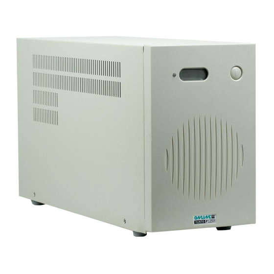
9. Anhang Vorder- und Rückansicht YUNTO P 500 / 750 17 / 54 2/6/2012... - Seite 18 Vorder- und Rückansicht YUNTO P 1250 18 / 54 2/6/2012...
- Seite 19 Manuale d’uso (YUNTO P 500, YUNTO P 750, YUNTO P 1250) Germania Italia Svizzera ONLINE USV-Systeme AG Online UPS Systems S.r.l. ONLINE USV-Systeme AG Dreimühlenstr.4 Via Edison 12 Industriestrasse 26 D-80469 München I-20058 Villasanta (Milano) CH-8604 Volketswil Phone +49 (0) 89 / 2423990-10...
-
Seite 20: Indice
Specifiche elettriche ................. 31 Autonomie tipiche (funzionamento in modo batteria) ......32 Dimensioni e peso ..................32 Condizioni ambientali di funzionamento ..........32 Porta di comunicazione (YUNTO P 500, YUNTO P 750, YUNTO P 1250) ........32 Appendice......................35 20 / 54 2/6/2012... -
Seite 21: Introduzione
2. Introduzione Gli ONLINE UPS YUNTO Serie P sono i più avanzati gruppi di continuità a tecno- logia Line-Interactive con forma d’onda in uscita di sinuoide simulata. La tecnolo- gia Line-Interactive si basa su una costante analisi della tensione elettrica di rete. In caso di scostamento della tensione dal valore ideale, nel giro di 2 ms, le utenze ven- gono alimentate direttamente dall’inverter dell’UPS. -
Seite 22: Norme Di Sicurezza
3. Norme di sicurezza LEGGERE ATTENTAMENTE E SEGUIRE LE ISTRUZIONI E LE NORME DI SICUREZZA DEL PRESENTE MANUALE PRIMA DELL’INSTALLAZIONE E DELLA MESSA IN FUNZIONE DELL’ UPS ! Trasporto Effettuate il trasporto del gruppo di continuità solo all’interno dell’imballo ori- ginale (protezione contro urti e scossoni). - Seite 23 Collocate i cavi in maniera che nessuno possa schiaccarli o inciampare. Funzionamento Non sconnettete il cavo di alimentazione dalla presa di rete o dall’UPS durante il funzionamento. In tal caso verrebbe a mancare istantaneamente la protezione (messa a terra) per il gruppo di continuità e per tutte le utenze ad esso collegate. ...
- Seite 24 Le batterie possono causare forti scosse elettriche e corto circuito. Nel caso di manutenzione delle batterie, seguire attentamente le seguenti norme di sicurezza: - Non indossare orologio, anelli ed eventuali ulteriori oggetti metallici. - Utilizzare solo attrezzi con impugnatura isolata. ...
-
Seite 25: Comandi E Segnalazioni
YUNTO P 500, YUNTO P 750 2. Avvia l’UPS da modo batteria (solo YUNTO P 500, YUN- TO P 750, YUNTO P 1250), qualora non presente la tensio- YUNTO P 1250) ne di rete. In questo caso, schiacciare il tasto On/Off in posi- zione ON, e premere il tasto reset per ca. - Seite 26 Segnala lo stato dell’UPS: LED di stato Funzionamento normale (LED illuminato in verde) Funzionamento in batteria o guasto-UPS (LED illuminato in rosso) Display di stato a Vengono visualizzate le seguenti indicazioni di stato: cristalli liquidi Funzionamento normale (NORMAL) (LCD) ...
-
Seite 27: Installazione E Messa In Funzione
5. Installazione e messa in funzione 1) Verificate le condizioni dell’imballo ed in caso di presenza di danneggiamenti avvertite immediatamente lo spedizioniere e ritirate la merce “con riserva”. Conservare l’imballo per eventuali utilizzi futuri. 2) Collegate l’UPS tramite cavo certificato VDE e marchiato CE ad una presa tri- polare. -
Seite 28: Eliminazione Dei Problemi
6. Eliminazione dei problemi Se il funzionamento dell’UPS presenta delle anomalie, provate ad eliminarle secon- do le istruzioni della seguente tabella: Problema Causa probabile Rimedio Schiacciare l’interruttore On/Off Nessuna tensione Interruttore On/Off in po- in uscita UPS sizione OFF (rilasciato) portandolo in posizione ON Danno alla protezione di Verificare il carico collegato... - Seite 29 Periodo di auto- Batterie non a pieno carico Ricaricate le batterie per almeno 4 nomia più breve / Batterie difettose ore e testate il tempo di autono- del valore previ- mia. Se il problema permane, ri- volgetevi al Vs. fornitore. Per una tempestiva assistenza comunicate le seguenti informazioni: 1.
-
Seite 30: Manutenzione
7. Manutenzione 7.1 Funzionamento L’UPS non richiede manutenzione da parte dell’utilizzatore. Passato un certo periodo (3-5 anni a 25°C) occorre sostituire le batterie dell’UPS. In questo caso rivolgetevi al Vs. fornitore. 7.2 Magazzinaggio In caso di magazzinaggio a temperature normali, caricate le batterie per 1-2 ore ogni tre mesi (consultate il capitolo “Installazione e messa in funzione”). -
Seite 31: Dati Tecnici
8. Dati tecnici 8.1 Specifiche elettriche Modello YUNTO P 500 YUNTO P 750 YUNTO P 1250 ENTRATA Tensione 230 V AC Frequenza 50 Hz Assorbimento 2,2 A 3,3 A 5,4 A (senza Carica- batterie) USCITA Potenza nomi- 500 VA 750 VA... -
Seite 32: Autonomie Tipiche (Funzionamento In Modo Batteria)
0 a 95 % senza condensa 8.5 Porta di comunicazione (YUNTO P 500, YUNTO P 750, YUNTO P 1250) E’ possibile collegare i computer alla porta di comunicazione (Contatti a potenziale zero) posta sul retro dell’UPS. Questo collegamento consente: ... - Seite 33 Per la realizzazione di queste funzioni devono avere una tensione continua tra il Pin 4 (Po positivamente) e il Pin 5 (massa) è applicato. Schema porta relais di comunicazione: Capacita delle batterie insufficiente 1kΩ Funzionamento in modo batteria 1kΩ 1kΩ Shut down UPS 1kΩ...
- Seite 34 Descrizione della funzione dei PIN: Pin-Nr. Funzionamento in mo- normalmente PIN 1 si cortocircuita con PIN 5 do batterie aperto (Massa), in caso di blackout o di tensione di rete in ingresso al di fuori del range permesso. Tensione potenziale Max.
-
Seite 35: Appendice
9. Appendice Fronte e Retro YUNTO P 500 / 750 35 / 54 2/6/2012... - Seite 36 Fronte e Retro YUNTO P 1250 36 / 54 2/6/2012...
- Seite 37 User Manual (YUNTO P 500, YUNTO P 750, YUNTO P 1250) Germany Italy Switzerland ONLINE USV-Systeme AG Online UPS Systems S.r.l. ONLINE USV-Systeme AG Dreimühlenstr.4 Via Edison 12 Industriestrasse 26 D-80469 München I-20058 Villasanta (Milano) CH-8604 Volketswil Phone +49 (0) 89 / 2423990-10...
-
Seite 38: Contents
Electrical specifications ................49 Typical stored energy time (Battery mode) ..........50 Dimensions and weights ................50 Operating environment ................50 Port connector (YUNTO P 500, YUNTO P 750, YUNTO P 1250) ..50 Annex ....................... 53 38 / 54 2/6/2012... -
Seite 39: Introduction
2. Introduction The Online UPS YUNTO P-Series is a newly developed Line-Interactive system with simulated sine wave for uninterruptible power supply. Line Interactive tech- nology is based on permanent analysis of the input voltage. If the voltage deviates from the ideal values or if it fails entirely, a high-performance inverter assumes the task of powering the loads within a period of 2 milliseconds. -
Seite 40: Safety Instructions
3. Safety Instructions PLEASE READ THROUGH AND FOLLOW THE USER MANUAL AND THE SAFETY INSTRUCTIONS BEFORE INSTALLING THE UNIT AND STARTING IT UP! Transport Please transport the UPS system only in the original packaging (to protect against shock and impact). Set-up ... - Seite 41 Do not connect appliances or items of equipment which would overload the UPS system (e.g. laser printers) to the UPS output sockets. Place the cables in such a way that no one can step on or trip over them. Operation ...
- Seite 42 take off wristwatches, rings and other metal objects use only tools with insulated grips and handles. When changing batteries, install the same number and same type of batteries. Do not attempt to dispose of batteries by burning them. This could cause battery explosion.
-
Seite 43: Indicators And Operating Controls
2 minutes, the audible alarm can no longer only YUNTO P 500, be deactivated in Battery mode). YUNTO P 750 2. Starts the UPS system from the batteries (only YUNTO... - Seite 44 DIP switches These switches may be set only by specialised personnel! (on rear panel) Switch 1: Reduces the lower threshold of input voltage at which the sys- tem switches over to Battery mode by 10 V (from 196V to 186V) in the ON position. Switch 2: Increases the output voltage by 5 % in the ON position.
-
Seite 45: Installation And Start Up
5. Installation and Start Up 1) Inspect the packaging carton and its contents for damage. Please inform the transport agency immediately should you find signs of damage. Please keep the packaging in a safe place for future use. 2) Connect the UPS system to a shockproof building-wiring socket outlet using a VDE-tested, CE-marked mains cable (e.g. -
Seite 46: Troubleshooting
6. Troubleshooting If the UPS system does not operate correctly, please attempt to solve the problem using the table below. Problem Possible cause Remedy No output voltage On/Off switch in position Set the On/Off switch to OFF (released) position ON (engaged) Line-side fuse of UPS sys- Check the load. - Seite 47 value ty. If the problem still per- sists, please consult your dealer. Please have the following information ready at hand before calling the After-Sales Service Department: 1. Model number, serial number 2. Date on which the problem occurred 3. Detailed description of the problem 47 / 54 2/6/2012...
-
Seite 48: Maintenance
7. Maintenance 7.1 Operation The UPS system contains no user-serviceable parts. If the battery service life (3 - 5 years at 25 °C ambient temperature) has been ex- ceeded, the batteries must be exchanged. Please consult your dealer in this case. 7.2 Storage If the batteries are to be stored in temperate climatic zones, they should be charged every three months for 8 hours (see Chapter "Installation and Switching On"). -
Seite 49: Technical Data
8. Technical Data 8.1 Electrical specifications Model YUNTO P 500 YUNTO P 750 YUNTO P 1250 INPUT Voltage 230VAC Frequenzy 50 Hz Current (without 2,2 A 3,3 A 5,4 A battery-charging) OUTPUT Power rating 500 VA 750 VA 1250 VA... -
Seite 50: Typical Stored Energy Time (Battery Mode)
0 to 95 %, no condensation 8.5 Port connector (YUNTO P 500, YUNTO P 750, YUNTO P 1250) A computer can be connected to the port connector (potential free contacts) on the rear panel of the UPS system. This allows ... - Seite 51 To realize these functions must be a DC voltage connected between PIN 4 (positive) and PIN 5 (ground). Port connector: Battery capacity low 1kΩ Battery mode 1kΩ 1kΩ UPS shut down 1kΩ 1kΩ Note: Optocouplers, max. 50VDC / 50mA 51 / 54 2/6/2012...
- Seite 52 Description of the PIN assignment: Pin No. Battery mode normally open PIN 1 is shorted to PIN 5 (ground) if the mains power supply fails or is out of toler- ance. Positive voltage po- Max. 50VDC tential Ground terminal UPS shut-down If a positive signal level (+ 5 V to + 12 V DC) is applied, the UPS system switches off (PIN 5...
-
Seite 53: Annex
9. Annex Front and back view, YUNTO P 500 / 750 53 / 54 2/6/2012... - Seite 54 Front and back view, YUNTO P 1250 54 / 54 2/6/2012...