Inhaltsverzeichnis
Werbung
Verfügbare Sprachen
Verfügbare Sprachen
Quicklinks
Benutzerhandbuch
Deutschland
ONLINE USV-Systeme AG
Luise-Ullrich-Str. 8
D-82031 Grünwald
Phone +49 (89) 2423990-10
Fax
+49 (89) 2423990-20
www.online-usv.de
ZE800_manual_ger_eng_it_V1.0.2.doc
ONLINE ZINTO E-Serie
Modell 800
Version: 1.0.2
Deutsch:
Seite
English:
Page
Italia:
Pagina
Italien
ONLINE UPS-Systems S.r.l.
Via Gilera Ferruccio 110
I-20862 Arcore (MB)
Phone +39 (039) 2051444
Fax
+39 (039) 2051435
www.online-ups.it
1 / 90
..............................................................................
1 -
30
31 -
60
61 -
90
Schweiz
ONLINE USV-Systeme AG
Eigenheimstraße 11
CH-8304 Wallisellen (Zürich)
Phone
+41 (44) 9452829
Fax
+41 (44) 9453288
www.online-usv.ch
R. Kistler
Werbung
Kapitel
Inhaltsverzeichnis
Fehlerbehebung

Verwandte Anleitungen für Online USV Modell 800


Inhaltszusammenfassung für Online USV Modell 800
-
Seite 1: Benutzerhandbuch
Benutzerhandbuch ONLINE ZINTO E-Serie Modell 800 Version: 1.0.2 Deutsch: Seite English: Page 31 - Italia: Pagina 61 - Deutschland Italien Schweiz ONLINE USV-Systeme AG ONLINE UPS-Systems S.r.l. ONLINE USV-Systeme AG Luise-Ullrich-Str. 8 Via Gilera Ferruccio 110 Eigenheimstraße 11 D-82031 Grünwald I-20862 Arcore (MB) CH-8304 Wallisellen (Zürich) - Seite 2 2 / 90 ZE800_manual_ger_eng_it_V1.0.2.doc R. Kistler ................
-
Seite 3: Inhaltsverzeichnis
Inhalt Benutzerhandbuch ................1 Einleitung ..................5 Sicherheitswarnungen ..............7 Montage ..................8 Überprüfung der Lieferung ..........8 Auspacken ................8 Überprüfung des Zubehörs ..........9 Inbetriebnahme ..............9 Betrieb ..................11 Bedienfeld ................. 11 Display ................11 Einstellungen ..............12 Betriebszustände............... - Seite 4 Abbildungsverzeichnis Abbildung 1: Prinzipschaltplan ............. 5 Abbildung 2: ZINTO E 800..............6 Abbildung 3: Bedienfeld ..............11 Abbildung 4: Display ................11 Abbildung 5: Einstellungen ..............12 Abbildung 6: RS232- und USB-Schnittstelle ........16 Abbildung 7: Entfernen der Frontblende..........20 Abbildung 8: Trennen der Batterie-Steckverbindung ......
-
Seite 5: Einleitung
E I N L E I T U N G 1. Einleitung Die ONLINE USV-Systeme AG (ONLINE) gehört zu den führenden Herstellern von unterbrechungsfreien Stromversorgungen (USV). Seit 1988 beschäftigt sich das deutsche Unternehmen mit Entwick- lung, Fertigung, Vertrieb und Support von USV-Systemen. Nach ver- kauften Stückzahlen sind die Produkte der ONLINE die deutsche... -
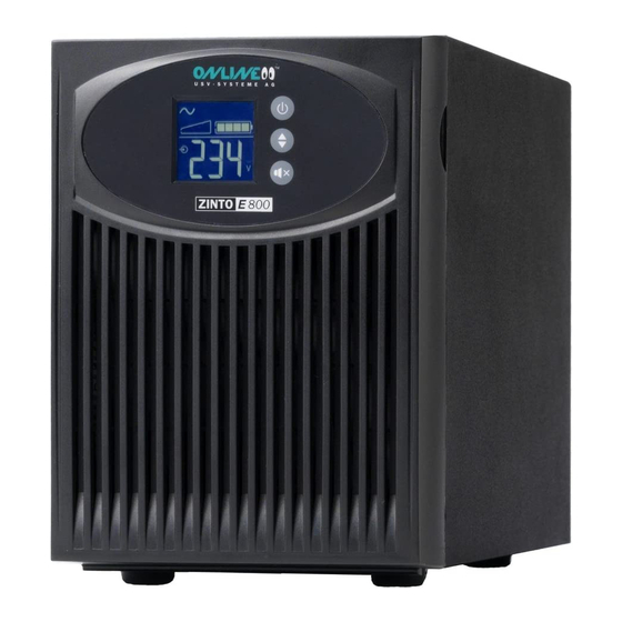
Seite 6: Abbildung 2: Zinto E 800
E I N L E I T U N G Daneben bietet die ZINTO E die folgenden Vorzüge: Kompakte Bauform Leises Betriebsgeräusch NAS-Kompatibilität Perfekte Sinus-Ausgangsspannung Wirkungsgrad von 95% EBM+ Ladetechnologie für 72 Monate Batterielebenserwar- tung ... -
Seite 7: Sicherheitswarnungen
S I C H E R H E I T S W A R N U N G E N 2. Sicherheitswarnungen Dieses Handbuch enthält wichtige Anweisungen, die Sie während der Installation und Wartung der USV-Anlage und der Batterien be- folgen müssen. -
Seite 8: Montage
M O N T A G E 3. Montage 3.1 Überprüfung der Lieferung Bewahren Sie die Transportkartons und das Verpackungsmaterial für die Spedition oder die Verkaufsstelle auf. Falls Anlagenteile wäh- rend des Transports beschädigt wurden, reichen Sie innerhalb von 24 Stunden eine Transportschaden-Reklamation bei Ihrem Lieferan- ten ein. -
Seite 9: Überprüfung Des Zubehörs
M O N T A G E 3.3 Überprüfung des Zubehörs RS-232 Schnittstellenkabel USB Schnittstellenkabel 10A Kaltgeräteverlängerung Software DataWatch Bedienungsanleitung Tabelle 1: Lieferumfang 3.4 Inbetriebnahme HINWEIS Vergewissern Sie sich, dass die Gesamtnennleistung aller angeschlossenen Geräte die Kapazität der USV-Anlage nicht überschreitet. - Seite 10 M O N T A G E HINWEIS Beim ersten Starten wird die Ausgangsfrequenz auf den Wert der Eingangsfrequenz gesetzt (die automatische Er- kennung ist standardmäßig aktiviert). 6. Schalten Sie die Verbraucher der Reihe nach ein. HINWEIS Die internen Batterien lassen sich in weniger als drei Stun- den auf 90% ihrer Kapazität aufladen.
-
Seite 11: Betrieb
B E T R I E B 4. Betrieb Dieser Abschnitt enthält Informationen über die Verwendung der ZINTO E, wie Nutzung des Bedienfeldes an der Vorderseite, Einstel- lungen, Betriebsarten sowie Starten und Abschalten der USV- Anlage. 4.1 Bedienfeld Abbildung 3: Bedienfeld 4.2 Display Abbildung 4: Display HINWEIS... -
Seite 12: Einstellungen
B E T R I E B 4.3 Einstellungen Wenn Sie die Scroll-Taste gedrückt halten, können Sie auf folgen- de Menüpunkte zugreifen: 5 Sekunden lang für das Menü „Output voltage“ 7 Sekunden lang für das Menü „Alarm“ 9 Sekunden lang für das Menü... -
Seite 13: Betriebszustände
B E T R I E B 4.4 Betriebszustände Der Status der USV-Anlage wird auf dem Bedienfeld angezeigt. Normalbetrieb Im Normalbetrieb leuchtet die Anzeige und die USV-Anlage wird vom Versorgungsnetz gespeist. Die USV-Anlage überwacht die Bat- terien und lädt diese je nach Bedarf auf. Die angeschlossenen Ver- braucher werden mit Strom versorgt. -
Seite 14: Starten Und Abschalten
B E T R I E B 4.5 Starten und Abschalten Starten 1. Stecken Sie das Netzanschlusskabel der USV-Anlage in eine Steckdose. Das Display an der USV-Anlage leuchtet auf. 2. Halten Sie die Taste an der USV-Anlage mindestens zwei Sekunden lang gedrückt. 3. - Seite 15 B E T R I E B Abschalten 1. Halten Sie die Taste an der USV-Anlage drei Sekunden lang gedrückt. Die USV-Anlage gibt ein kurzes akustisches Signal. Die USV- Anlage wechselt in den Standby-Betrieb und die Anzeige erlischt. HINWEIS Wird die Taste nach weniger als drei Sekunden losgelas- sen, so kehrt die USV-Anlage wieder zu ihrer vorherigen Be- triebsart zurück.
-
Seite 16: Kommunikation
K O M M U N I K A T I O N 5. Kommunikation 5.1 RS232- und USB-Schnittstelle Um die Kommunikation zwischen der USV-Anlage und einem Com- puter herzustellen, schließen Sie den Computer mithilfe eines geeig- neten Datenkabels (Kabel im Lieferumfang) an die RS-232- oder USB-Schnittstelle der USV-Anlage an (siehe Abbildung 6). -
Seite 17: Datawatch Software
K O M M U N I K A T I O N 1. Schließen Sie Kabel (5) oder (6) an die RS-232- bzw. USB- Schnittstelle des zu schützenden Rechnersystems an (Kabel im Lieferumfang enthalten). 2. Schließen Sie das jeweils andere Ende der Kabel (5) oder (6) an die USB-Schnittstelle (1) bzw. -
Seite 18: Wartung
W A R T U N G 6. Wartung 6.1 Pflege und Wartung Für eine lange Lebensdauer sollte der Bereich um die USV-Anlage sauber und staubfrei sein. Falls es in der Umgebung der USV- Anlage sehr staubig ist, reinigen Sie die Außenflächen der Anlage mit einem Staubsauger. -
Seite 19: Batteriewechsel
W A R T U N G 6.4 Batteriewechsel HINWEIS Entfernen Sie die Batterien nicht, solange die USV-Anlage im Batteriebetrieb läuft. Dank der Hot-Swap-Funktion können die Batterien ohne vorheriges Abschalten der USV-Anlage und ohne Trennen der angeschlosse- nen Verbraucher ausgetauscht werden. Falls Sie die USV-Anlage vor dem Batteriewechsel lieber vom Netz trennen möchten, lesen Sie den Abschnitt „Starten und Abschalten“. -
Seite 20: Abbildung 7: Entfernen Der Frontblende
W A R T U N G ACHTUNG GEFAHR EINES ELEKTRISCHEN SCHLAGS. Nehmen Sie auf keinen Fall selbst Veränderungen an der Verkabelung oder den Anschlüssen der Batterie vor. Der Versuch, eigen- ständig die Verkabelung der Batterie zu verändern, kann zu ernsthaften Verletzungen führen ... -
Seite 21: Abbildung 8: Trennen Der Batterie-Steckverbindung
W A R T U N G 2. Trennen Sie die Batte- rie-Steckverbindung, Ziehen Sie bitte nicht an den Kabeln (siehe Abbildung 8). Abbildung 8: Trennen der Batterie- Steckverbindung 3. Entfernen Sie die Me- tall-Schutzabdeckung, die mit einer Schraube gesichert (siehe Abbildung 9). -
Seite 22: Entsorgen Der Altbatterien Oder Der Usv-Anlage
W A R T U N G 5. Tauschen Sie die Batterien im Batterieeinschub aus. HINWEIS Überprüfen Sie, ob die Ersatzbatterien dieselben Spezifikati- onen aufweisen wie die Altbatterien. Lesen Sie den Abschnitt Entsorgen der Altbatterien oder der USV-Anlage für eine sachgemäße Entsorgung. 6. -
Seite 23: Fehlerbehebung
F E H L E R B E H E B U N G 7. Fehlerbehebung Die ZINTO E ist für den selbstständigen Betrieb ausgelegt und mel- det eventuell auftretende Probleme automatisch im Display. 7.1 Warnmeldungen Betriebszustand Mögliche Ursache Maßnahme Die Ausgangsleistung der Verringern Sie die angeschlossene Überlastung... -
Seite 24: Allgemeine Fehler
F E H L E R B E H E B U N G 7.2 Allgemeine Fehler Betriebszustand Mögliche Ursache Maßnahme USV-Anlage Die Batterien müssen aufge- Schließen Sie die USV-Anlage 48 stellt nicht die er- laden oder getauscht wer- Stunden an den Netzstrom an, um wartete Zeit für die den. -
Seite 25: Support
F E H L E R B E H E B U N G 7.4 Support Als deutscher Anbieter garantiert ONLINE direkte Ansprechbarkeit, unbürokratische Bearbeitung und kürzeste Reaktionszeiten. Umfas- sende Unterstützung ist selbstverständlich – vor und nach dem Kauf. Bei ONLINE werden umfassende Support- und Serviceleistungen groß... -
Seite 26: Technische Daten
T E C H N I S C H E D A T E N 8. Technische Daten 8.1 Spezifikation Modell ZINTO E 800 Artikel-Nr. ZE800 Elektrische Eigenschaften Nennleistung (VA/W) 800VA / 625W Technologie Line-Interactive mit Sinusausgangsspannung und Buck- &-Boost-Funktion Eingangsspannung und 184 - 276V Frequenzbereiche... -
Seite 27: Rückansicht
T E C H N I S C H E D A T E N 8.2 Rückansicht Beschreibung der Kommunikationsfunktionen siehe Abbildung 6 Abbildung 11: Rückansicht 27 / 90 ZE800_manual_ger_eng_it_V1.0.2.doc R. Kistler ................ -
Seite 28: Ce Bestätigung
T E C H N I S C H E D A T E N 8.3 CE Bestätigung 28 / 90 ZE800_manual_ger_eng_it_V1.0.2.doc R. Kistler ................ -
Seite 29: Garantie
G A R A N T I E 9. Garantie Die ONLINE USV-Systeme AG (ONLINE) gewährleistet, dass dieses Produkt für die Dauer von zwei Jahren ab Kaufdatum frei von Mate- rial- und Fertigungsfehlern ist. Die Verpflichtung von ONLINE gemäß dieser Garantie ist auf die Reparatur oder den Ersatz (Entscheidung trifft ONLINE) jeglicher defekter Produkte begrenzt. - Seite 30 30 / 90 ZE800_manual_ger_eng_it_V1.0.2.doc R. Kistler ................
-
Seite 31: User Manual
English: Page 31 - Italia: Pagina 61 - Germany Italy Switzerland ONLINE USV-Systeme AG ONLINE UPS-Systems S.r.l. ONLINE USV-Systeme AG Luise-Ullrich-Str. 8 Via Gilera Ferruccio 110 Eigenheimstraße 11 D-82031 Grünwald I-20862 Arcore (MB) CH-8304 Wallisellen (Zürich) Phone +49 (89) 2423990-10... - Seite 32 32 / 90 ZE800_manual_ger_eng_it_V1.0.2.doc R. Kistler ................
- Seite 33 Contents User Manual ..................31 Introduction ................35 Safety warnings ................ 37 Installation ................38 Inspecting the shipment ............ 38 Unpacking the UPS system ..........38 Checking the accessories ..........39 Commissioning ..............39 Operation .................. 41 Control panel ..............41 Display ................
- Seite 34 List of figures Figure 1: Principle wiring diagram ............35 Figure 2: ZINTO E 800 ............... 36 Figure 3: Control panel ............... 41 Figure 4: Display ................. 41 Figure 5: Settings ................42 Figure 6: RS232 and USB interface ........... 46 Figure 7: Removing the front cover ............
-
Seite 35: Introduction
I N T R O D U C T I O N 1. Introduction ONLINE USV-Systeme AG (ONLINE) is one of the leading manufac- turers of Uninterruptible Power Supplies (UPS). Since 1988, the German company has specialised in the development, manufacture, and sales and support of UPS systems. -
Seite 36: Figure 2: Zinto E 800
I N T R O D U C T I O N In addition, ZINTO E provides the following advantages: Compact construction Quiet operating noise NAS compatibility Perfect sinusoidal output voltage 95% efficiency EBM+ charging technology for expected 72-month battery ser- vice life ... -
Seite 37: Safety Warnings
S A F E T Y W A R N I N G S 2. Safety warnings This handbook contains important instructions that you must comply with during the installation and maintenance of the UPS system and the batteries. Please read these instructions completely before you begin working with the device. -
Seite 38: Installation
I N S T A L L A T I O N 3. Installation 3.1 Inspecting the shipment Keep the shipping cartons and the packaging material for the ship- ping company or the sales agency. If parts of the system were dam- aged during transport, please submit a transport damage claim to your supplier within 24 hours. -
Seite 39: Checking The Accessories
I N S T A L L A T I O N 3.3 Checking the accessories RS232 interface cable USB interface cable 10A low-heat devices power cord extension DataWatch software Operating instructions Table 1: Package 3.4 Commissioning NOTE Make sure that the total nominal power of all connected de- vices does not exceed the capacity of the UPS system. - Seite 40 I N S T A L L A T I O N NOTE When starting for the first time, the output frequency is set to the value of the input frequency (the automatic detection is enabled by default). 6. Switch on the consumers one after the other. NOTE The internal batteries will charge up to 90% of their capacity in less than three hours.
-
Seite 41: Operation
O P E R A T I O N 4. Operation This section contains information on the use of ZINTO E, like the use of the front control panel, settings, operating modes, and starting and stopping the UPS system. 4.1 Control panel Figure 3: Control panel 4.2 Display Figure 4: Display... -
Seite 42: Settings
O P E R A T I O N 4.3 Settings If you keep the scroll button pressed, you can access the following menu items: 5 seconds long for the "Output voltage" menu 7 seconds long for the "Alarm" menu ... -
Seite 43: Operating States
O P E R A T I O N 4.4 Operating states The status of the UPS system is displayed on the control panel. Normal mode In normal mode, the display lights up continuously and the UPS system is supplied by the mains power supply. The UPS system monitors the batteries and charges these as needed. -
Seite 44: Startup And Shutdown
O P E R A T I O N 4.5 Startup and shutdown Startup 1. Plug the power cable of the UPS system into a socket. The display of the UPS system lights up. 2. Keep the button on the UPS system pressed for at least two seconds. - Seite 45 O P E R A T I O N Shutdown 1. Keep the button on the UPS system pressed for three sec- onds. The UPS system emits a brief acoustic signal. The UPS sys- tem switches to standby mode and the display goes out.
-
Seite 46: Communication
C O M M U N I C A T I O N 5. Communication 5.1 RS232 and USB interface To establish communication between the UPS system and a com- puter, connected the computer to the RS232 or USB interface of the UPS system using a suitable data cable (included in delivery) (see Figure 6). -
Seite 47: Datawatch Software
C O M M U N I C A T I O N 1. Connect cable (5) or (6) to the RS-232 or USB interface of the computer system to be protected (cable included in delivery). 2. Connect the other end of cable (5) or (6) to the USB interface (1) or RS232 port (2) of the UPS system. -
Seite 48: Maintenance
M A I N T E N A N C E 6. Maintenance 6.1 Care and maintenance To ensure a long service life of the system, the area around the UPS system should be kept clean and free of dust. If the area around the system is very dusty, clean the outer surfaces of the system using a vacuum cleaner. -
Seite 49: Battery Change
M A I N T E N A N C E 6.4 Battery change NOTE Do not remove the batteries while the UPS system is running in battery mode. Thanks to the hot-swap function, the batteries can be replaced with- out shutting down the UPS system and without having to disconnect the connected loads. -
Seite 50: Figure 7: Removing The Front Cover
M A I N T E N A N C E CAUTION DANGER OF AN ELECTRICAL SHOCK. Do not perform modifications to the cabling or the connections of the batter- ies yourself. Attempting to modify the cabling of the batteries yourself can lead to serious injuries ... -
Seite 51: Figure 8: Disconnecting The Battery Plug Connection
M A I N T E N A N C E 2. Disconnect the battery plug connection whilst making sure you does not pull on the cable (see Figure 8). Figure 8: Disconnecting the battery plug con- nection 3. Remove the protective metal cover, which is secured with a screw (see Figure 9). -
Seite 52: Disposing Of Old Batteries Or The Ups System
M A I N T E N A N C E 5. Replace the batteries in the battery module insert. NOTE Check whether the replacement batteries have the same specifications as the old batteries. Please read the "Disposing of old batteries or the UPS sys- tem"... -
Seite 53: Troubleshooting
T R O U B L E S H O O T I N G 7. Troubleshooting ZINTO E is designed for independent operation and automatically indicates any problems on the display. 7.1 Warning messages Operating state Possible causes Measure The output power of the Reduce the connected load. -
Seite 54: General Faults
T R O U B L E S H O O T I N G 7.2 General faults Operating state Possible causes Measure The UPS system batteries must Connect the UPS system to the does not make the charged or replaced. mains power for 48 hours to charge expected time... -
Seite 55: Support
T R O U B L E S H O O T I N G 7.4 Support As German provider, ONLINE guarantees direct responsiveness, hassle-free processing and the shortest reaction times. Comprehen- sive support is understood – before and after the purchase. At ONLINE, comprehensive support and service solutions are our top priority. -
Seite 56: Technical Data
T E C H N I C A L D A T A 8. Technical data 8.1 Specification Model ZINTO E 800 Article number ZE800 Electrical properties Nominal output (VA/W) 800VA / 625W Technology Line-interactive with sinusoidal output voltage and buck- boost function Input voltage and 184 - 276V... -
Seite 57: Rear View
T E C H N I C A L D A T A 8.2 Rear view Description of the communication functions, see Figure 6 Figure 11: Rear view 57 / 90 ZE800_manual_ger_eng_it_V1.0.2.doc R. Kistler ................ -
Seite 58: Ce Conformity
T E C H N I C A L D A T A 8.3 CE conformity 58 / 90 ZE800_manual_ger_eng_it_V1.0.2.doc R. Kistler ................ -
Seite 59: Warranty
W A R R A N T Y 9. Warranty ONLINE USV-Systeme AG (ONLINE) hereby warrants this product to be free from defects in material and workmanship for a period of two years from the date of purchase. The obligation of ONLINE un- der this warranty is limited to the replacement or repair of any prod- uct which proves upon our examination to be defective. - Seite 60 60 / 90 ZE800_manual_ger_eng_it_V1.0.2.doc R. Kistler ................
-
Seite 61: Manuale Dell'utente
English: Page 31 - Italia: Pagina 61 - Germania Italia Svizzera ONLINE USV-Systeme AG ONLINE UPS-Systems S.r.l. ONLINE USV-Systeme AG Luise-Ullrich-Str. 8 Via Gilera Ferruccio 110 Eigenheimstraße 11 D-82031 Grünwald I-20862 Arcore (MB) CH-8304 Wallisellen (Zürich) Phone +49 (89) 2423990-10... - Seite 62 62 / 90 ZE800_manual_ger_eng_it_V1.0.2.doc R. Kistler ................
- Seite 63 Indice Manuale dell'utente ................61 Introduzione ................65 Avvertenze di sicurezza ............67 Montaggio ................. 68 Controllo della fornitura ............. 68 Disimballaggio dell’UPS ............ 68 Controllo degli accessori ........... 69 Messa in funzione ............. 69 Funzionamento ................. 71 Quadro di comando ............71 Display ................
- Seite 64 Elenco delle figure Figura 1: Schema di principio ............. 65 Figura 2: ZINTO E 800 ............... 66 Figura 3: Quadro di comando ............. 71 Figura 4: Display ................. 71 Figura 5: Impostazioni ................ 72 Figura 6: Interfaccia RS232 e interfaccia USB ........76 Figura 7: Smontaggio del pannello frontale ........
-
Seite 65: Introduzione
I N T R O D U Z I O N E 1. Introduzione ONLINE USV-Systeme AG (ONLINE) è un'azienda tedesca leader nel settore dei gruppi di continuità (UPS), attiva dal 1988 nello svi- luppo, produzione, commercializzazione e assistenza di sistemi UPS. - Seite 66 I N T R O D U Z I O N E Inoltre ZINTO E offre i seguenti vantaggi: Forma compatta Funzionamento silenzioso Compatibilità NAS Tensione di uscita sinusoidale perfetta Rendimento del 95% Tecnologia di carica EBM+ per una durata prevista della batte- ria di 72 mesi ...
-
Seite 67: Avvertenze Di Sicurezza
A V V E R T E N Z E D I S I C U R E Z Z A 2. Avvertenze di sicurezza Il presente manuale contiene istruzioni importanti da osservare du- rante l'installazione e la manutenzione del sistema UPS e delle bat- terie. -
Seite 68: Montaggio
M O N T A G G I O 3. Montaggio 3.1 Controllo della fornitura Il cliente è tenuto al momento della consegna a premettere alla firma sul documento di consegna del trasportatore la dicitura “RITIRATO CON RISERVA DI VERIFICA”. In caso contrario, le compagnie assi- curative non accettano il rimborso della merce e di conseguenza ONLINE non potrà... -
Seite 69: Controllo Degli Accessori
M O N T A G G I O Per il disimballaggio della scatola e degli accessori: 1. Aprire il cartone esterno e prelevare gli accessori imballati con il sistema UPS. 2. Prelevare l’UPS dal cartone esterno sollevandolo con cautela. 3. - Seite 70 M O N T A G G I O AVVERTENZA Al primo avvio la frequenza di uscita viene impostata sul va- lore della frequenza d'ingresso (il rilevamento automatico è attivato di default). 6. Attivare le utenze, una dopo l'altra. AVVERTENZA Le batterie interne si ricaricano in meno di tre ore fino al 90% della loro capacità.
-
Seite 71: Funzionamento
F U N Z I O N A M E N T O 4. Funzionamento Nel presente paragrafo sono contenute informazioni sull'utilizzo di ZINTO E, come l'uso del quadro di comando sul lato frontale, le mo- dalità di funzionamento e l'avvio e lo spegnimento dell’UPS.. 4.1 Quadro di comando Figura 3: Quadro di comando 4.2 Display... -
Seite 72: Impostazioni
F U N Z I O N A M E N T O 4.3 Impostazioni Tenendo premuto il tasto Scroll si può accedere alle seguenti voci del menu: Premendo per 5 secondi si arriva al menu "Output voltage" Premendo per 7 secondi si arriva al menu "Alarm"... -
Seite 73: Modalità D'esercizio
F U N Z I O N A M E N T O 4.4 Modalità d’esercizio Lo stato dell’UPS viene visualizzato sul quadro di comando. Funzionamento normale In modalità di funzionamento normale il simbolo è costantemente acceso e l’UPS viene alimentato dalla rete di alimentazione. L’UPS monitora le batterie e le ricarica se necessario. -
Seite 74: Avvio E Spegnimento
F U N Z I O N A M E N T O 4.5 Avvio e spegnimento Avvio dell’UPS 1. Collegare il cavo di alimentazione ad una presa di corrente. Il display dell’UPS si accende. dell’UPS per almeno due secondi. 2. - Seite 75 F U N Z I O N A M E N T O Disattivazione dell’UPS per almeno tre secondi. 1. Premere il tasto L’UPS emette un breve segnale acustico, commuta sulla mo- dalità Standby e il simbolo si spegne. AVVERTENZA Se il tasto viene rilasciato dopo meno di tre secondi, l’UPS torna alla modalità...
-
Seite 76: Comunicazione
C O M U N I C A Z I O N E 5. Comunicazione 5.1 Interfaccia RS232 e interfaccia USB Per ripristinare la comunicazione tra l’UPS e un computer, collegare il computer a una delle interfacce di comunicazione dell’UPS me- diante un cavo dati idoneo (cavo fornito in dotazione) (vedi Figura 6). -
Seite 77: Software Datawatch
C O M U N I C A Z I O N E 1. Collegare il cavo (5) o (6) all'interfaccia RS-232 o USB del si- stema computer da proteggere (cavo compreso nella dotazio- ne). 2. Collegare l'altra estremità del cavo (5) o (6) all'interfaccia USB (1) o alla porta RS-232 (2) dell’UPS. -
Seite 78: Manutenzione
M A N U T E N Z I O N E 6. Manutenzione 6.1 Cura e manutenzione dell’UPS e delle batterie Per una lunga durata del sistema è necessario che l'area circostante l'UPS sia pulita e priva di polvere. Se l'area in cui si trova l’UPS è molto polverosa, pulire le superfici esterne del sistema con un aspi- rapolvere. -
Seite 79: Sostituzione Delle Batterie
M A N U T E N Z I O N E 6.4 Sostituzione delle batterie AVVERTENZA Non rimuovere le batterie finché l’UPS funziona nella modali- tà a batteria. Grazie alla funzione hot-swap è possibile sostituire le batterie senza prima spegnere l’UPS e senza separare i carichi collegati. Se prima di sostituire le batterie si desidera separare l’UPS dalla re- te, leggere il paragrafo "Avvio e spegnimento". - Seite 80 M A N U T E N Z I O N E ATTENZIONE PERICOLO DI SCOSSA ELETTRICA. Non apportare in al- cun caso modifiche al cablaggio o ai collegamenti della bat- teria. Il tentativo di modificare in proprio il cablaggio della bat- teria può...
- Seite 81 M A N U T E N Z I O N E 2. Staccare collega- mento a innesto della batteria, senza tirare il cavo (vedi Figura 8). Figura 8: Distacco del collegamento a innesto delle batterie 3. Togliere la protezione metallica, che è...
-
Seite 82: Smaltimento Delle Batterie Vecchie O Dell'ups
M A N U T E N Z I O N E 5. Sostituire le batterie nell'inserto batterie. AVVERTENZA Verificare che le batterie sostitutive abbiano le stesse speci- fiche delle batterie vecchie. Per uno smaltimento corretto leggere il paragrafo "Smalti- mento delle batterie vecchie o dell’UPS". -
Seite 83: Risoluzione Dei Guasti
R I S O L U Z I O N E D E I G U A S T I 7. Risoluzione dei guasti L’UPS ZINTO E è predisposto per il funzionamento autonomo e se- gnala automaticamente sul display eventuali problemi durante il fun- zionamento. -
Seite 84: Guasti Generali
R I S O L U Z I O N E D E I G U A S T I 7.2 Guasti generali Segnale di Possibile causa Misura allarme o stato L’UPS non mette a Collegare l’UPS alla corrente di rete Le batterie devono essere disposizione caricate o sostituite. -
Seite 85: Servizio Assistenza
R I S O L U Z I O N E D E I G U A S T I 7.4 Servizio Assistenza In qualità di fornitore tedesco, ONLINE garantisce disponibilità im- mediata, un'elaborazione semplificata delle richieste e brevi tempi di reazione. -
Seite 86: Dati Tecnici
D A T I T E C N I C I 8. Dati tecnici 8.1 Specifiche dei sistemi UPS Modello ZINTO E 800 Cod. articolo ZE800 Caratteristiche elettriche Potenza nominale (VA/W) 800VA / 625W Tecnologia Line interactive con tensione in uscita sinusoidale e fun- zione buck &... -
Seite 87: Vista Posteriore Dell'ups
D A T I T E C N I C I 8.2 Vista posteriore dell’UPS Descrizione delle funzioni di comunicazione, vedi Figura 6 Figura 11: Vista posteriore 87 / 90 ZE800_manual_ger_eng_it_V1.0.2.doc R. Kistler ................ -
Seite 88: Dichiarazione Ce
D A T I T E C N I C I 8.3 Dichiarazione CE 88 / 90 ZE800_manual_ger_eng_it_V1.0.2.doc R. Kistler ................ -
Seite 89: Garanzia
Tutti i contenuti sono protetti dal diritto d'autore. Copyright © 2014 di ONLINE USV-Systeme AG. Tutti i diritti riservati. È vietata la riprodu- zione, integrale o parziale, senza autorizzazione. 89 / 90 ZE800_manual_ger_eng_it_V1.0.2.doc... - Seite 90 90 / 90 ZE800_manual_ger_eng_it_V1.0.2.doc R. Kistler ................