BEHA TELARIS' 010 Bedienungsanleitung
Inhaltsverzeichnis
Quicklinks
12 month Warranty
Display ............................................0...50 V
Resolution ......................................0,1 V at I∆N 100, 300, 500, 1000mA
........................................................1V at I∆N 10, 30mA
Tolerance ........................................-0%...+10% /+6 Digit
Limits .............................................25V / 50V, contact voltage limit UL to be pre-selected
Auto function
Measurement ranges .....................10,30, 100, 300, 500, 1000mA idem
........................................................100, 300, 500, 1000 mA selective
Test currents ..................................0.5 x I∆N,
........................................................1 x I∆N,
........................................................2 x I∆N,
........................................................5 x I∆N (not at I∆N = 500 / 1000 mA (S) ),
........................................................automatic selection, also refer to table A
Phase position ................................0° / 180°, automatic selection
Measurement time ..........................see table C, when exceeding limits, immediate cut-off
Display ............................................O.K. / bad ( POS / Err )
Limits .............................................25V / 50V, contact voltage limit UL to be pre-selected
Mains Voltage Range
Measurement range ........................3...300V AC
Tolerance ........................................+/-(3%+3 Digit)
Frequency range .............................50/60Hz +/- 10%
Internal resistance ...........................approx. 300kΩ
Overvoltage protection ....................400V AC/DC
12 month Warranty
UNITEST instruments are subject to strict quality control. However, should the instrument function impro-
perly during daily use, your are protected by our 12 months warranty (valid only with invoice).We will
repair free of charge any defects in workmanship or material, provided the instrument is returned unope-
ned and untampered with, i.e. with undamaged warranty label.Any damage due to dropping or incorrect
handling are not covered by the warranty. If the instrument shows failure following expiration of warranty,
our service department can offer you a quick and economical repair.
CH. BEHA GmbH
Elektronik - Elektrotechnik
In den Engematten 14
D-79286 Glottertal
Tel.:07684/ 8009-0
Fax.:07684/ 8009-10
Internet.: http://www.beha.de
Subject to technical changes without notice! 05/99
48
UNITEST
Bedienungsanleitung Best.-Nr.: 9061
Instruction Manual Cat. No. 9061
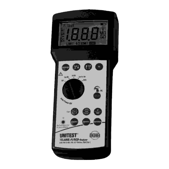
TELARIS Fi/RCD Analyzer
PTDB9061-00
®
®
• TELARIS 0100
®
• TELARIS ERDE
®
• TELARIS ISO
• TELARIS Fi/RCD
®
• TELARIS S C H L E I F E
Inhaltsverzeichnis

Verwandte Anleitungen für BEHA TELARIS' 010


Inhaltszusammenfassung für BEHA TELARIS' 010
- Seite 1 If the instrument shows failure following expiration of warranty, our service department can offer you a quick and economical repair. CH. BEHA GmbH • TELARIS Fi/RCD Elektronik - Elektrotechnik...
- Seite 2 Testing Contact Voltage UB Measurement conditions ....0.4 I∆N Measurement time ......<2s,when exceeding limits, immediate cut-off Measurement range ......0,6V ... 70,0 V at I∆N 100, 300, 500, 1000mA ............1V...70,0V at I∆N 10, 30mA Resolution ........0,1 V at I∆N 100, 300, 500, 1000mA Tolerance ........-0%...+10% /+6 Digit Limits ..........5V / 50V, contact voltage limit UL to be pre-selected Testing Ground Resistance RE...
-
Seite 3: Inhaltsverzeichnis
General Technical Data I n h a l t s v e r z e i c h n i s F I / R C D - T y p e Current Type Current Type Test Current prescribed Test Time S t a n d a r d FI/RCD Inhaltsverzeichnis . -
Seite 4: Test Current Prescribed
2000ms, I∆N≥100mA: 500ms Sie haben ein hochwertiges Meßgerät der Firma Ch. 1 St. Tragetasche / Nylon BEHA GmbH erworben, mit dem Sie über einen sehr 1 St. Bedienungsanleitung 1 0 < t < 2 0 0 m s5 0 0 m s VDE 664-1 ¸... -
Seite 5: Technical Data
Technical Data Sicherheitsmaßnahmen / Bestimmungsgemäße Ve rw e n d u n g F I / R C D - T y p e Current Type Current Type Test Current prescribed Test Time S t a n d a r d FI/RCD 3 . -
Seite 6: Display / Bedienelemente
Display / Bedienelemente Technical Data 4 . 0 Display / Bedienelemente 12.0 Technical Data D i s p l a y Table A Test Currents: 1 . Achtung, Warnsymbol I∆N UB/RE- x 0 . 5 2 . Symbol für Zeit-/Stromüberschreitung Measurement: 3 . -
Seite 7: Battery Replacement / Maintenance
Battery Replacement / Maintenance Durchführen von Messungen / Spannungsmessung Energy Management returned to their point of sale. 5 . 0 Durchführen von Messungen Approximately 5 minutes after last key operation, the instrument switches off automatically (auto- Please, comply with the appropriate regulati- Messungen in gefährlicher Nähe elektrischer power-off). -
Seite 8: Fi/Rcd-Prüfung Allgemein
Fi / RCD-Prüfung allgemein Infrared Interface, send Measurement Data 5 . 2 Fi/RCD-Prüfung allgemein Infrared Interface, send Measurement Delete Last Stored Measurement Value: Das Telaris Fi-RCD Analyzer bietet die Möglichkeit, Hinter der Fehlerstrom-Schutzeinrichtung vor- Data 4 Set measurement range selection switch (30) die Auslösezeiten von Standard –... -
Seite 9: Funktion Ub/Re
Thermometer-Symbol gestartet beschrieben mit dem Prüfobjekt verbinden (12) together with the phase position of nominal saving. CH. BEHA will not be held liable for finan- 4 Die gewünschte Meßfunktion UB/ RE mittels werden, da diese Ströme das Gerät nicht erwärmen. - Seite 10 Starting Automatic RCD Test with RCD Tripping Löst der Fi/RCD aus, wird dies durch das "Achtung” Bei erscheinen des Symbols "Steckdosenfehler” Symbol (1) und das "Steckdosen fehler”- Symbol (4) 5.2.4 Starting Automatic RCD Test with RCD (4) liegt ein PE-Fehler vor. angezeigt.
-
Seite 11: Starten Der Fi/Rcd-Prüfung Mit Auslösen Des Fi/Rcd
Starten der Fi/RCD-Prüfung mit Auslösen des FI/RCD, Funktion tA/UB 5 . 2 . 2 Starten der Fi/RCD-Prüfung mit Auslösen Die wählbaren Stromarten und Multiplikatoren If trip time tA of an RCD exceeds 200ms, the The ramp current must be between 50% and des FI/RCD, Funktion tA/UB bei dem gewählten Nennfehlerstrom sind in der Ta- measurement value for trip time is displayed as... -
Seite 12: Starten Der Fi/Rcd-Prüfung Mit Auslösen Des Fi/Rcd, Funktion I
Starten der FI/RCD-Prüfung mit Auslösen des FI/RCD, Funktion I< /ta / UB Die Messung wird abgebrochen, wenn die "Die Meßergebnisse können durch Drücken der The RCD test is continued after successful preli- Berührungsspannung das eingestellte Berührungs- Taste Speichern (23) abgespeichert werden. minary test. - Seite 13 Starting RCD Test with RCD Tripping, Function I</ta/UB Die FI-Prüfung wird nach erfolgreichem Vortest fort- The measurement is interrupted if the Measurement results may be saved pressing gesetzt. Bei der Stromart ‘AC’ wird mit einem Fehler- contact voltage exceeds the set contact voltage key Save (23).
- Seite 14 Starting RCD Test with RCD Tripping, Funvtion ta/UB Wenn die Auslösezeit tA des FI/RCD größer als Der Rampenstrom muß zwischen 50% und 100% 5.2.2 Starting RCD Test with RCD Tripping, The current types and multiplication factors 200ms ist, dann erscheint als Meßwert für die Aus- I∆N liegen, ansonsten ist der FI/RCD defekt, dies wird Funvtion ta/UB to be selected at set nominal residual current are...
-
Seite 15: Starten Der Fi-Prüfung Auto Mit Auslösen Des Fi/Rcd
Starten der Fi/ RCD-Prüfung Auto mit Auslösen des FI / RCD If the RCD trip, the ?"Attention" symbol (1) and 5 . 2 . 4 Starten der Fi/ RCD-Prüfung Auto mit Aus- If the symbol "Socket Error" (14) is display- "Socketerror"... -
Seite 16: Speichern Von Meßwerten
I∆N for selec- strom-Multiplikator (12) zusammen mit der Phasen- verloren gehen oder verändert werden. CH. BEHA on the display. Subsequent measurements can tive RCDs. lage des Nennfehlerstroms (9) gibt einen Hinweis GmbH übernimmt keine Haftung für finanzielle oder... -
Seite 17: General Information About Rcd Tests
General Information about RCD Tests Datenübertragung durch Infrarotschnittstelle 5.2 General Information about RCD Tests 7 . 0 Datenübertragung durch Meßwerte um 1 vermindert wird und ein weite- Any leakage current (within the current cir- The instrument TELARIS RCD Analyzer allows the I n f r a r o t s c h n i t t s t e l l e rer Signalton ertönt. -
Seite 18: 0 . 0 B A T T E R I E W E C H S E L
Batteriewechsel / Wa r t u n g General Information to carry out Measurements 1 0 . 0 B a t t e r i e w e c h s e l 1 1 . 0 W a r t u n g 5.0 General Information to carry out Das Gerät vor dem Batteriewechsel von allenMeß- Das Meßgerät benötigt bei einem Betrieb gemäß... -
Seite 19: Technische Daten
Display / Operation Elements Technische Daten 4.0 Display / Operation Elements 12.0 Technische Daten Display Tabelle A Prüfströme: 1. Attention, warning symbol I∆N U B / R E - M e s s u n g : x 0 . 5 2. -
Seite 20: Transport And Storage
Transport and Storage / Safety Measures F I / R C D - T y p S t r o m - S t r o m f a k t o r P r ü f s t r o m vorgeschriebene P r ü... -
Seite 21: Introduction / Scopy Of Supply
1 pc carrying holster / nylon you to carryout measurement over a long time 1 pc instruction manual period. The company Ch. BEHA GmbH is a mem- ber of the world -wide operating BEHA Group with its head office in Glottertal/Schwarzwald wich also... - Seite 22 Contents F F I / R C D - T y p S t r o m S t r o m f a k t o r P r ü f s t r o m vorgeschriebene P r ü f z e i t N o r m FI/RCD Contents...
- Seite 23 Prüfung der Berührspannung UB: M e ß b e d i n g u n g e n :..... . 0.4 I∆N M e ß...
- Seite 24 12 Monate Garantie ® UNITEST A u f l ö s u n g :........1 m s T o l e r a n z :.