Sharp PG-C20XU, PG-C20XE Handbuch
Inhaltsverzeichnis
Verfügbare Sprachen
Verfügbare Sprachen
Quicklinks
In the interests of user-safety (Required by safety regulations in some countries) the set should be restored
to its original condition and only parts identical to those specified should be used.
Im lnteresse der Benutzersicherheit (erforderliche Sicherheitsregeln in einigen Ländern) muß das Gerät in seinen
Originalzustand gebracht werden. Außerdem dürfen für die spezifizierten Bauteile nur identische Teile verwendet
werden.
SHARP CORPORATION
SERVICE MANUAL
SERVICE-ANLEITUNG
LCD PROJECTOR
LCD PROJEKTOR
MODELS
MODELLE
This document has been published to be used for
after sales service only.
1
The contents are subject to change without notice.
S31Q7PG-C20XU
PG-C20XU
PG-C20XE
ATTACHMENT ADAPTOR
ANSCHLUSSADAPTER
AN-Z7T
PG-C20XU
PG-C20XE
AN-Z7T
Inhaltsverzeichnis

Verwandte Anleitungen für Sharp PG-C20XU, PG-C20XE


Inhaltszusammenfassung für Sharp PG-C20XU, PG-C20XE
-
Seite 43: Technische Daten
7204CEZZ (PG-C20XU), TINS-7271CEZZ (PG-C20XE)), Kurzanleitungen für den LCD-Projektor (TINS-7205CEZZ (PG-C20XU), TINS-7272CEZZ (PG-C20XE), TINS-7284CEZZ (PG-C20XE), TINS-7285CEZZ (PG-C20XE)) Dieser Projektor von SHARP ist mit 3 LCD-(Flüssigkristallanzeige) Dieses Gerät hat einige inaktive,innerhalb akzeptierter Toleranzgrenzen Projektionspaneels ausgestattet. Diese neuartigen Projektionspaneels liegende TFTs, die als beleuchtete oder als nicht aktive Punkte auf der enthalten TFTs (Dünnfilmtransistoren) mit insgesamt 786.432... -
Seite 44: Hinweise Für Das
PG-C20XU PG-C20XE AN-Z7T HINWEIS FÜR DAS WARTUNGSPERSONAL 1 2 3 4 5 6 7 8 9 0 1 2 3 4 5 6 7 8 9 0 1 2 3 4 5 6 7 8 9 0 1 2 1 2 3 4 5 6 7 8 9 0 1 2 3 4 5 1 2 3 4 5 6 7 8 9 0 1 2 3 4 5 6 7 8 9 0 1 2 3 4 5 6 7 8 9 0 1 2 1 2 3 4 5 6 7 8 9 0 1 2 3 4 5 Auswechseln der Lampe ACHTUNG: UV-STRAHLUNG... -
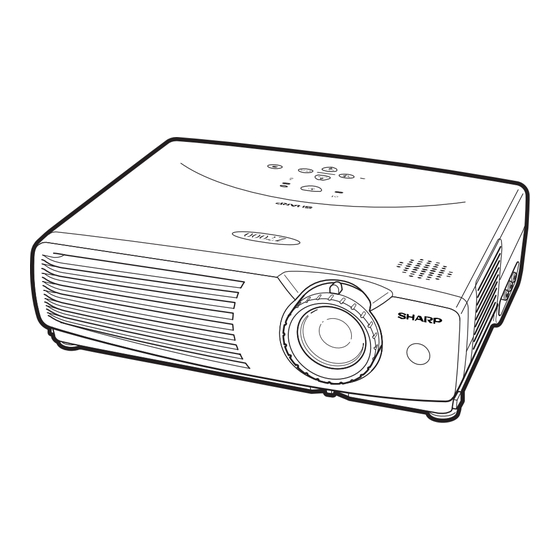
Seite 45: Lage Der Bedienelemente
PG-C20XU PG-C20XE AN-Z7T Lage der Bedienelemente Projektor Ansicht von vorne und oben Betriebs-Taste (ON/OFF) Lampenaustausch-Anzeige ON/OFF LAMP POWER Betriebs-anzeige Temperaturwarnanzeige TEMP. KEYSTONE Automatische Eingang-/Zur ü ck-Taste Synchronisierung-/Eingabe- INPUT AUTO SYNC (INPUT/BACK) Taste (AUTO SYNC/ENTER) BACK ENTER MENU Trapezverzeichnungs-/ Einstellungs-Tasten Menü-Taste (MENU) (KEYSTONE/ ]/[) Luftfilter/Kühlventilator Zoom-Knopf... -
Seite 46: Fernbedienung
PG-C20XU PG-C20XE AN-Z7T Fernbedienung Vorderansicht Ansicht von hinten Maus-(]/[)/ Maustaste (> ) Einstellungs-(]/[) Tasten Netz-Taste Linke Klick-/ Maustaste (< ) (POWER) Zurück-taste (L-CLICK/ Rechte Klick-/ BACK) MAUS-T aste Eingabe-Taste (MOUSE) (R-CLICK/ENTER) Vergrößern-Taste Standbild-Taste (ENLARGE) (FREEZE) Auto-Synchron-Taste Menü-Taste (AUTO SYNC) (MENU) AV-Stummschaltungs- Eingangs-Taste Taste (AV MUTE) -
Seite 47: Verwendung Als Eine Drahtlose Maus
PG-C20XU PG-C20XE AN-Z7T Positionierung der Fernbedienung bzw. des Mausempfängers Die Fernbedienung kann zur Steuerung des Projektors innerhalb des unten gezeigten Bereiches verwendet werden. Der Fernbedienungs-Mausempfänger kann mit der Fernbedienung zusammen zur Steuerung der Mausfunktion eines angeschlossenen Computers innerhalb des unten gezeigten Bereiches verwendet werden. Das Signal der Fernbedienung kann für einen einfacheren Betrieb von der Bildwand reflektiert werden. -
Seite 48: Pin-Belegung
PG-C20XU PG-C20XE AN-Z7T Pin-Belegung Computer-Eingangsport 1 (COMPUTER INPUT 1): 15-Pin Mini-D-Sub-Buchse Computereingang Analog 1. Videoeingang (rot) 9. Nicht belegt 2. Videoeingang 10. Nicht belegt (Grün/Sync. auf Grün) 11. MASSE 3. Videoeingang (blau) 12. Bi-direktionale Daten 4. Nicht belegt 13. Horizontales Sync.- 5. -
Seite 49: Abmessungen
PG-C20XU PG-C20XE AN-Z7T Abmessungen Ansicht der Rückseite Ansicht von oben Seitenansicht Ansicht von vorne Anhang Ansicht von unten Einheit:mm... -
Seite 50: Entfernen Der Hauptteile
PG-C20XU PG-C20XE AN-Z7T ENTFERNEN DER HAUPTTEILE 1. Abnehmen der Einlaßabdeckung und der Lampen-Einheit. 1-1. Die Einlaßabdeckung abnehmen. 1-2. Die Halteschraube aus der Lampenabdeckung herausdrehen, dann die Lampenabdeckung abnehmen. 1-3. Die beiden Halteschraube aus der Lampen-Einheit herausdrehen, dann die Lampen-Einheit ausbauen. Einlaßabdeckung Lampen-Einheit Lampenabdeckung... -
Seite 51: Abnehmen Der Vorderen Und Oberen Verkleidungen
PG-C20XU PG-C20XE AN-Z7T 2. Abnehmen der vorderen und oberen Verkleidungen 2-1. Die drei Halteschrauben (silberfarben) aus der vorderen Verkleidung herausdrehen. 2-2. Die sieben Halteschrauben (silberfarben) aus der oberen Verkleidung herausdrehen. 2-3. Die mit ∗ markierten Stellen der oberen Verkleidung nach unten drücken, um die Haken zu lösen; danach die obere Verkleidung abnehmen. -
Seite 52: Temperatursensor
PG-C20XU PG-C20XE AN-Z7T 3. Ausbau der Platine-Ausgabeeinheit, des Fernbedienungs-Sensors, der Platine-Empfängereinheit für die Fernbedienung und der Lüfter-Einheit 3-1. Die fünf Halteschrauben (gelb) aus der Platine-Ausgabeeinheit herausdrehen.Die Massefeder und die elektrostatische Schutzfolie entfernen. 3-2. Die Platine-Ausgabeeinheit anheben, die Stecker abziehen, dann die Platine-Ausgabeeinheit herausheben. 3-3. -
Seite 53: Ausbau Der Vorderen Luftführungseinheit, Pc-I/F-Platine Und Der Optik-Einheit
PG-C20XU PG-C20XE AN-Z7T 4.Ausbau der vorderen Luftführungseinheit, PC-I/F-platine und der Optik-Einheit 4-1. Die Halteschraube (silberfarben) aus dem Bimetall herausdrehen, dann das Bimetall abnehmen. 4-2. Die beiden Halteschrauben (eine schwarze und eine silberfarbene) aus der vorderen Luftführungseinheit herausdrehen, dann die vordere Luftführungseinheit ausbauen. 4-3. - Seite 54 PG-C20XU PG-C20XE AN-Z7T 5. Ausbau der Ballast-/Leistungs-/Netzeingangseinheit-Platine, des Kühlgebläses und des Spannungswählschalters 5-1. Die Halteschraube (gelb oder silberfarben) aus der Ballast-Abdeckung herausdrehen. Das Teflon-Klebeband entfernen, das zur Befestigung der Steckerkabel an der Ballast-Abdeckung dient. Die Ballast-Abdeckung herausnehmen. 5-2. Die drei Halteschrauben (gelb oder silberfarben) aus der Ballast-Platineneinheit herausdrehen. Die Stecker aus der Leistungs-Platineneinheit herausdrehen, dann die Ballast-Platineneinheit entfernen.
-
Seite 55: Ausbau Der Mittleren Luftführung Und Des Pbs-Kühlgebläses
PG-C20XU PG-C20XE AN-Z7T 6. Ausbau der Anschlußklemmen-/ 3D Y/C-Trennplatinen-Einheit 6-1. Die beiden Halteschrauben (gelb) und die beiden Halterungen aus der Anschlußklemmen-/dreidimensionalen Y/C-Trennplatinen-Einheit herausdrehen. Die Platineneinheit zur Seite schieben und die Anschlußklemmen aus der Bodenplatte herausziehen. 6-2. Den Stecker (EA) von der Anschlußklemmen-Platineneinheit abziehen. 7. -
Seite 56: Rückstellen Des Lampenbetriebszeit-Timers
PG-C20XU PG-C20XE AN-Z7T Rückstellen des Lampenbetriebszeit-Timers Rückstellen des Lampenbetriebszeit-Timers Nach dem Auswechseln der Lampe muß der Lampenbetriebszeit-Timer entsprechend den nachfolgenden Anweisungen zurückgestellt werden. Lichtquelle (Lampe) Die als Lichtquelle verwendete Lampe weist eine Lebensdauer von ungefähr 1000 Stunden auf. Nachdem die Gesamtbetriebszeit mehr als 900 Stunden beträgt, muß... -
Seite 57: Beschreibung Der Optik-Einheit
PG-C20XU PG-C20XE AN-Z7T Beschreibung der Optik-Einheit Erläuterungen für das korrekte Setup der optischen Komponenten und Baugruppen (Ansicht von oben) Projektionsobjektiv Eingabe-polarisator B Eingabe-Polarisator R Beleuchtungsquelle Relaislinse (Lampe) LCD(R) LCD(B) Zweifarbiges Kreuzprisma Fliegenaugenoptik (Eingang) Fliegenaugenoptik (Ausgang) Sammellinse R UV-Absorptionsscheibe LCD(G) Eingabe-Polarisator G Relaislinse Sammellinse G Grün... -
Seite 58: Einstellen Der Spiegel
PG-C20XU PG-C20XE AN-Z7T Einstellen der Spiegel Diese Einstellung wird erforderlich, wenn eine der Komponenten des optischen Mechanismus ersetzt wurde. 1. Die Flachkabel von allen LCD-Tafeln abziehen. 2. Die Lampe einschalten. 3. Ein Weißlicht-Bild projizieren und überprüfen, ob in irgendeinem Bereich der Abbildung ein Farbton zu sehen ist. Wenn Farbtöne angezeigt werden, die Halteschrauben der Lichteinfall-Gleitplatte lösen, dann die Gleitplatte so einstellen, daß... -
Seite 59: Auswechseln Der Prismenhalter-Einheit
PG-C20XU PG-C20XE AN-Z7T Auswechseln der Prismenhalter-Einheit 1. Die drei Halteschrauben herausdrehen, dann die Prismenhalter-Einheit und die Objektiv-Einheit aus der Optik-Einheit herausnehmen. 2. Die vier Halteschrauben entfernen, dann die Prismenhalter-Einheit und die Objektiv-Einheit trennen. 3. Die Prismenhalter-Einheit durch ein Neuteil ersetzen. Die obigen Schritte 1 und 2 in umgekehrter Reihenfolge ausführen. -
Seite 60: Videoeinstellung
PG-C20XU PG-C20XE AN-Z7T ELEKTRISCHE EINSTELLUNGEN Einen Signalgenerator bzw. einen PC oder Macintosh-Computer an den Projektor anschließen, um die Signale zuzuführen, die in den Einstellbedingungen aufgeführt sind. ADJUSTMENT PRECAUTIONS 1 Vorsichtsmaßnahmen bei der Initialisierung Es dauert nur 5 Sekunden, um den Speicher zu initialisieren und die Anfangseinstellungen zu überschreiben. Bei der Initialisierung wechselt der Bildschirm-Hintergrund der Menüanzeige auf Rot, und die Meldung „INITIALIZE“... - Seite 61 PG-C20XU PG-C20XE AN-Z7T Einstellgegenstand Einstellbedingungen Einstellverfahren » Zuerst eine Einstellung vornehmen, wo sich der 10- Einstellung des 1. Das XGA 10-Stufensignal RGB-Antriebs zuführen. Farbtonpegel sättigt. Danach ist die Einstellung um 2. Die folgende Gruppe, einen Punkt zu erniedrigen. Untergruppe bzw. Positionen wählen.
- Seite 62 PG-C20XU PG-C20XE AN-Z7T Nr. Einstellgegenstand Einstellbedingungen Einstellverfahren » Den Steuerschalter des Geräts oder die Taste der Einstellung der 1. Ein Gegenspannungs- RGB- Einstellsignal im XGA- Fernbedienungseinheit verwenden, um die Gegenspannung Modus zuführen Einstellung vorzunehmen, daß 2. Die folgende Gruppe, Bildschirmflickern auf ein Minimum reduziert ist. »...
- Seite 63 PG-C20XU PG-C20XE AN-Z7T Einstellgegenstand Einstellbedingungen Einstellverfahren » Sicherstellen, daß die Einstellung der nachfolgenden Einstellung der 1. Das NTSC 10-Stufensignal Video-Helligkeit zuführen. Beschreibung entspricht. (BRIGHTNESS) 2. Die folgende Gruppe, PG-C20XU ..142 Untergruppe und Position PG-C20XE ..145 wählen. Gruppe: Adjust VIDEO Image Untergruppe: VPC3230 Position: Bright »...
- Seite 64 PG-C20XU PG-C20XE AN-Z7T Nr. Einstellgegenstand Einstellbedingungen Einstellverfahren Einstellung der 1. AMP-R-Gain wählen, dann die Signalamplitude 1. Die folgende Gruppe, auf 3,8 ± 0,1 Vs-s einstellen. Eingangs- Untergruppe bzw. signal-Amplitude 2. AMP-R-BLK wählen, dann die Signalamplitude Positionen wählen. des Weiß-Weiß-Signals auf 2,1 ± 0,1 Vs-s des VIDEO- Gruppe: Adjust VIDEO Image Eingabefelds...
- Seite 65 PG-C20XU PG-C20XE AN-Z7T Einstellgegenstand Einstellbedingungen Einstellverfahren » Benutzereinstellung: Überprüfung der 1. Ein Audiosignal zuführen. Audio- Die Lautstärkeleistung überprüfen. Leistungswerte » Benutzereinstellung: Überprüfung der 1. Das RGB-Signal RGB- empfangen. Die Geräteleistung in bezug auf Kontrast, Helligkeit, Leistungswerte Rot, Blau, Takt, Phase, H-POS und V-POS überprüfen.
-
Seite 66: Prozeßmenü
PG-C20XU PG-C20XE AN-Z7T Prozeßmenü 1 Gruppe Untergruppe Position R-Bright R-Contrast G-Bright G-Contrast B-Bright B-Contrast AMP-R-BLK Adjust PC Image AMP-R-GAIN AMP-G-BLK AMP-G-GAIN CXA2111R AMP-B-BLK AMP-B-GAIN AMP-BLK AMP-GAIN Bright Contrast VPC3230 Color H-Position AMP-R-BLK AMP-R-Gain Adjust VIDEO Image AMP-G-BLK AMP-G-Gain CXA2111R AMP-B-BLK AMP-B-Gain CLPLVL PRGLEV... - Seite 67 G_REVHCONV B_REVHCONV LCD4 (Adjust Conv) R_VCONV G_VCONV B_VCONV Adjust Vert. Conv R_REVVCONV G_REVVCONV B_REVVCONV Boot Code Config Sharp Table Version Rom Code Sub CPU Inside Temp/ref Temp Outside Temp/ref Temp/Fan State Lamp Fan Fan Speed Other Fan Gamma Off on/off...
-
Seite 68: Fehlersuchtabelle
PG-C20XU PG-C20XE AN-Z7T FEHLERSUCHTABELLE Überprüfung der grundlegenden Ist die POWER LED NEIN eingeschaltet, oder blinkt sie rot oder grün? Mit dem Abschnitt "Überprüfung des Netzteils" fortfahren. Kann das Gerät mit der Einschalttaste oder über NEIN die Fernbedienungseinheit eingeschaltet werden? Mit dem Abschnitt "Überprüfung der Mikrocomputer-Peripherieschaltkreise"... - Seite 69 PG-C20XU PG-C20XE AN-Z7T Überprüfen des Netzteils Sind die Stecker CN751, NEIN P1707 und P3701 fest eingesteckt? Sind die Stecker CN751, P1707 und P3701 fest eingesteckt? NEIN Ist die Lampenabdeckung fest geschlossen? Die Lampenabdeckung fest schließen. Ist der Bimetall-Schalter NEIN ausgeschaltet? Den Bimetall-Schalter ersetzen.
- Seite 70 PG-C20XU PG-C20XE AN-Z7T Überprüfung der Mikrocomputer- Peripherieschaltkreise Liegt eine Spannung von NEIN ca. 3 V an Stift (33) (RCS) von IC1601 an? Die Abdeckung des Einlaßfilters auf inkorrekte Einpassung sowie das Kühlgebläse auf Funktionsstörung überprüfen. NEIN Ist SW1602 auf "NORMAL" gesetzt? SW1602 auf die "NORMAL"- Position setzen.
- Seite 71 PG-C20XU PG-C20XE AN-Z7T Überprüfung des PLL- Schaltkreises Liegt ein 120-MHz- NEIN Taktsignal an Stift (8) von IC8001 an? Liegt ein 40-MHz- NEIN Taktsignal an Stift (9) von IC8001 an? Liegt ein 16-MHz- NEIN Taktsignal an Stift (7) von IC8001 an? IC8001 oder dessen periphärer Schaltkreis defekt.
- Seite 72 PG-C20XU PG-C20XE AN-Z7T Überprüfung der Ausgangsleitung NEIN Liegen Video-Eingangssignale an P8001 und SC1701 auf gerissene TP1401, TP1402 und TP1403 an? Lötstellen überprüfen. Q8013, Q8014, Q8015 Liegen Video-Ausgangssignale an und deren periphäre den Stiften (42), (44) und (46) von Schaltkreise IC8024 an? überprüfen.
- Seite 73 PG-C20XU PG-C20XE AN-Z7T Überprüfung des RGB- Eingangssignals Das RGB-Synchrontrennsignal dem Anschluß INPUT1 zuführen (Stift (15) von D-SUB). INPUT1 (RGB) mit der Gerätetaste oder der Fernbedienungseinheit wählen. Treten Bildstörungen auf? NEIN Erscheint die Anzeige NO SIGNAL? Mit dem Abschnitt "Überprüfung des Synchronsignals" fortfahren. Erscheinen die Farben R, G NEIN und B?
- Seite 74 PG-C20XU PG-C20XE AN-Z7T Überprüfung der Eingangssignal-Einstellung Entspricht die NEIN Eingangssignal-Einstellung der Spezifikation? Das spezifizierte Signal wählen. NEIN Ist der Stecker korrekt angeschlossen? Den Stecker wieder anschließen. Ende Überprüfung des Synchronsignals Liegt ein vertikales NEIN Synchronsignal an TP8003 Liegt ein horizontales NEIN Synchronsignal an Stift (3) der Anschlußklemmen-...
- Seite 75 PG-C20XU PG-C20XE AN-Z7T Überprüfung des RGB- Signals Um das Eingangssignal überprüfen zu können, muß der Signalgenerator auf das Farbabstufungssignal eingestellt werden. Mit dem Oszilloskop die Kontaktstege (R-, G- und B- Eingangssignale an IC8026) von C8204, C8208 und C8213 überprüfen. IC8026 oder dessen Liegt das spezifizierte periphärer Schaltkreis defekt.
- Seite 76 PG-C20XU PG-C20XE AN-Z7T Überprüfung des SOG- Schaltkreises Mit dem Oszilloskop den Kontaktsteg von R8231 (Stift (32) von IC8026) überprüfen. Liegt das zusammengesetzte Synchronsignal an? Ende NEIN Mit dem Oszilloskop den NEIN Kontaktsteg von R8110 (Sockel von Q8010) überprüfen. Ist das Liegt ein Videosignal NEIN Synchronsignal im...
- Seite 77 PG-C20XU PG-C20XE AN-Z7T Überprüfung des Video- Synchronsignals Mit dem Oszilloskop das Signal an TL8006 messen. (Das vertikale Synchronsignal überprüfen.) Entspricht das vertikale NEIN Synchronsignal der Spezifikation? Mit dem Oszilloskop das Signal an TL8009 messen. (Das horizontale Synchronsignal überprüfen.) Mit dem Abschnitt Entspricht das horizontale NEIN "Überprüfung der...
- Seite 78 PG-C20XU PG-C20XE AN-Z7T Überprüfung des digitalen Signalverarbeitungs- Schaltkreis NEIN Liegt ein 40-MHz- Taktsignal an FL8024 an? Mit dem Abschnitt "Überprüfung des PLL- Schaltkreises" fortfahren. NEIN Liegt ein 38-MHz-Impuls- signal (Synchronsignal) an FL8026 an? Liegt ein 60-MHz-Impuls- IC8022, IC8021 oder NEIN signal (Synchronsignal) an deren periphäre FL8025 an?
- Seite 79 PG-C20XU PG-C20XE AN-Z7T Überprüfung des Audiosignals Liegen Audio-Audiosignale NEIN an den Stiften (7) von IC3301 und IC3302 an? Das Audiokabel berpr fen. IC3301 und IC3302 miteinander vertauschen, um die periph ren Schaltkreise zu berpr fen. NEIN Liegt Spannung an Stift (4) von IC1901 an? Zuerst R1914, dann den Leistungsschaltkreis berpr fen.
- Seite 80 PG-C20XU PG-C20XU PG-C20XE PG-C20XE AN-Z7T AN-Z7T CHASSIS LAYOUT / CHASSIS-ANORDNUNG...
-
Seite 81: Blockschaltbild
PG-C20XU PG-C20XU PG-C20XE PG-C20XE AN-Z7T AN-Z7T BLOCK DIAGRAM / BLOCKSCHALTBILD... -
Seite 82: Gesamtschaltplan
PG-C20XU PG-C20XU PG-C20XE PG-C20XE AN-Z7T AN-Z7T OVERALL WIRING DIAGRAM / GESAMTSCHALTPLAN... -
Seite 83: Beschreibung Des Schematischen Schaltplans
PG-C20XU PG-C20XE AN-Z7T DESCRIPTION OF BESCHREIBUNG DES SCHEMATIC DIAGRAM SCHEMATISCHEN SCHALTPLANS VOLTAGE MEASUREMENT CONDITION: SPANNUNGSMESSUNGEN: 1. Voltages at test points are measured at the 1. Spannungen an den Prüfpunkten werden bei einer Netzspannung von 220V gemessen, Signale werden supply voltage of AC 220V. Signals are fed by a für die Wartung mit einem Farbbalken-Signal generator color bar signal generator for servicing purpose and zugeführt, und Spannungen werden mit einem... - Seite 84 PG-C20XU PG-C20XE AN-Z7T WAVEFORMS / WELLENFORMEN 1 TP1101 2 TP1201 3 TP1301 4 IC8003(55)pin (TL8009) (RSIG1) (GSIG1) (BSIG1) (H-OUT) H : 10µ sec/div H : 10µ sec/div H : 10µ sec/div H : 20µ sec/div V : 2V/div V : 2V/div V : 2V/div V : 1V/div 5 IC8003 (72)pin...
- Seite 85 PG-C20XU PG-C20XU PG-C20XE PG-C20XE AN-Z7T AN-Z7T Ë OUTPUT UNIT / AUSGABEEINHEIT-1/7...
- Seite 86 PG-C20XU PG-C20XU PG-C20XE PG-C20XE AN-Z7T AN-Z7T Ë OUTPUT UNIT / AUSGABEEINHEIT-2/7...
- Seite 87 PG-C20XU PG-C20XU PG-C20XE PG-C20XE AN-Z7T AN-Z7T Ë OUTPUT UNIT / AUSGABEEINHEIT-3/7...
- Seite 88 PG-C20XU PG-C20XU PG-C20XE PG-C20XE AN-Z7T AN-Z7T Ë OUTPUT UNIT / AUSGABEEINHEIT-4/7...
- Seite 89 PG-C20XU PG-C20XU PG-C20XE PG-C20XE AN-Z7T AN-Z7T Ë OUTPUT UNIT / AUSGABEEINHEIT-5/7...
- Seite 90 PG-C20XU PG-C20XU PG-C20XE PG-C20XE AN-Z7T AN-Z7T Ë OUTPUT UNIT / AUSGABEEINHEIT-6/7...
- Seite 91 PG-C20XU PG-C20XU PG-C20XE PG-C20XE AN-Z7T AN-Z7T Ë OUTPUT UNIT / AUSGABEEINHEIT-7/7...
- Seite 92 PG-C20XU PG-C20XU PG-C20XE PG-C20XE AN-Z7T AN-Z7T Ë INPUT UNIT / EINGANGSEINHEIT-1/3...
- Seite 93 PG-C20XU PG-C20XU PG-C20XE PG-C20XE AN-Z7T AN-Z7T Ë INPUT UNIT / EINGANGSEINHEIT-2/3...
- Seite 94 PG-C20XU PG-C20XU PG-C20XE PG-C20XE AN-Z7T AN-Z7T Ë INPUT UNIT / EINGANGSEINHEIT-3/3...
- Seite 95 PG-C20XU PG-C20XE AN-Z7T Ë R/C RECEIVER UNIT / FERNBEDIENUNGSEMPFÄNGERSEINHEIT...
-
Seite 96: Ë Operation Board Unit/ Bedienungsplatineneinheit
PG-C20XU PG-C20XE AN-Z7T Ë OPERATION BOARD UNIT/ BEDIENUNGSPLATINENEINHEIT... - Seite 97 PG-C20XU PG-C20XU PG-C20XE PG-C20XE AN-Z7T AN-Z7T Ë 3D Y/C SEPARATE UNIT / EINHEIT...
- Seite 98 PG-C20XU PG-C20XU PG-C20XE PG-C20XE AN-Z7T AN-Z7T Ë POWER AND INLET UNIT / NETZTEILEINHEIT UND EINLASSEINHEIT...
- Seite 99 PG-C20XU PG-C20XU PG-C20XE PG-C20XE AN-Z7T AN-Z7T Ë PC I/F UNIT / PC-I/F-EINHEIT-1/7...
- Seite 100 PG-C20XU PG-C20XU PG-C20XE PG-C20XE AN-Z7T AN-Z7T Ë PC I/F UNIT / PC-I/F-EINHEIT-2/7...
- Seite 101 PG-C20XU PG-C20XU PG-C20XE PG-C20XE AN-Z7T AN-Z7T Ë PC I/F UNIT / PC-I/F-EINHEIT-3/7...
- Seite 102 PG-C20XU PG-C20XU PG-C20XE PG-C20XE AN-Z7T AN-Z7T Ë PC I/F UNIT / PC-I/F-EINHEIT-4/7...
- Seite 103 PG-C20XU PG-C20XU PG-C20XE PG-C20XE AN-Z7T AN-Z7T Ë PC I/F UNIT / PC-I/F-EINHEIT-5/7...
- Seite 104 PG-C20XU PG-C20XU PG-C20XE PG-C20XE AN-Z7T AN-Z7T Ë PC I/F UNIT / PC-I/F-EINHEIT-6/7...
- Seite 105 PG-C20XU PG-C20XU PG-C20XE PG-C20XE AN-Z7T AN-Z7T Ë PC I/F UNIT / PC-I/F-EINHEIT-7/7...
-
Seite 106: Printed Wiring Board Assemblies
PG-C20XU PG-C20XE AN-Z7T PRINTED WIRING BOARD ASSEMBLIES LEITERPLATTENEINHEITEN R/C Receiver Unit (Wiring Side) Fernbedienungsempfängerseinheit (Leiterbahnseite) Output Unit (Wiring Side) Ausgabeeinheit (Leiterbahnseite) - Seite 107 PG-C20XU PG-C20XE AN-Z7T R/C ReceiverUnit (Component Side) Fernbedienungsempfängerseinheit (Bestückungsseite) Output Unit (Component Side) Ausgabeeinheit (Bestückungsseite)
- Seite 108 PG-C20XU PG-C20XE AN-Z7T 3D Y/C Separation Unit (Wiring Side) 3D Y/C-Trennplatinen-Einheit (Leiterbahnseite) Inlet Unit (Wiring Side) Input Unit (Wiring Side) Einlasseinheit (Leiterbahnseite) Eingangseinheit (Leiterbahnseite)
- Seite 109 PG-C20XU PG-C20XE AN-Z7T 3D Y/C Separation Unit (Component Side) 3D Y/C-Trennplatinen-Einheit (Bestückungsseite) Input Unit (Component Side) Inlet Unit (Component Side) Eingangseinheit (Bestückungsseite) Einlasseinheit (Bestückungsseite)
- Seite 110 PG-C20XU PG-C20XE AN-Z7T Power Unit (Wiring Side) PC I/F Unit (Wiring Side) Netzteinheit (Leiterbahnseite) PC-I/F-einheit (Leiterbahnseite)
- Seite 111 PG-C20XU PG-C20XE AN-Z7T PC I/F Unit (Component Side) Power Unit (Component Side) PC-I/F-einheit (Bestückungsseite) Netzteinheit (Bestückungsseite)
-
Seite 112: Parts List
Contact your nearest SHARP Parts Distributor. For location of SHARP Parts Distributor, 5. KODE 6. QUANTITÄT Please call Toll-Free; 1-800-BE-SHARP in CANADA: Contact SHARP Electronics of Canada Limited Phone (416) 890-2100. MARK: SPARE PARTS-DELIVERY SECTION MARKIERUNG : ERSATZTEILE-LIEFERUNG Ref. No. -
Seite 133: Anschlussadapter
Contact your nearest SHARP Parts Distributor. For location of SHARP Parts Distributor, 5. KODE 6. QUANTITÄT Please call Toll-Free; 1-800-BE-SHARP in CANADA: Contact SHARP Electronics of Canada Limited Phone (416) 890-2100. MARK: SPARE PARTS-DELIVERY SECTION MARKIERUNG : ERSATZTEILE-LIEFERUNG Ref. No. - Seite 135 PG-C20XU PG-C20XE AN-Z7T...
- Seite 136 Code Ref. No. Part No. Description Code COPYRIGHT © 2001 BY SHARP CORPORATION ALL RIGHTS RESERVED. No part of this publication may be reproduced, stored in a retrieval system, or transmitted in any form or by any means, electronic, mechanical, photocopying, recording, or otherwise, without prior written permission of the publisher.