Sharp PG-C45X Anleitung
Inhaltsverzeichnis
Verfügbare Sprachen
Verfügbare Sprachen
Quicklinks
In the interests of user-safety (Required by safety regulations in some countries) the set should be restored
to its original condition and only parts identical to those specified should be used.
Im lnteresse der Benutzersicherheit (erforderliche Sicherheitsregeln in einigen Ländern) muß das Gerät in seinen
Originalzustand gebracht werden. Außerdem dürfen für die spezifizierten Bauteile nur identische Teile verwendet
werden.
CONTENTS
» SPECIFICATIONS ............................................. 2
NOTES (for USA) ............................................... 3
» NOTE TO SERVICE PERSONNEL ................... 4
» OPERATION MANUAL ...................................... 8
» REMOVING OF MAJOR PARTS ..................... 13
» RESETTING THE TOTAL LAMP TIMER ......... 15
» THE OPTICAL UNIT OUTLINE ....................... 16
» ELECTRICAL ADJUSTMENT ........................... 20
» TROUBLE SHOOTING TABLE ........................ 29
» CHASSIS LAYOUT .......................................... 90
» BLOCK DIAGRAM ........................................... 92
» OVERALL WIRING DIAGRAM ........................ 94
» SCHEMATIC DIAGRAM .................................. 96
Ë ELECTRICAL PARTS ................................ 148
Ë CABINET AND MECHANICAL PARTS ..... 164
Ë ACCESSORIES PARTS ............................ 169
Ë PACKING PARTS ....................................... 169
» PACKING OF THE SET ................................. 170
SHARP CORPORATION
SERVICE MANUAL
SERVICE-ANLEITUNG
MODEL
MODELL
Page
» TECHNISCHE DATEN .................................... 48
» BEDIENUNGSANLEITUNG ............................ 51
» AUSBAU WICHTIGER TEILE ......................... 56
» RÜCKSTELLUNG DESLAMPEN-TIMERS ..... 58
» ELEKTRISCH EINSTELLUNG ........................ 63
» FEHLERSUCHTABELLE ................................. 72
» CHASSIS-ANORDNUNG ................................ 90
» BLOCKSCHALTBILD ....................................... 92
» GESAMTSCHALTPLAN .................................. 94
» SCHEMATISCHER SCHALTPLAN ................. 96
» LEITERPLATTENEINHEITEN ....................... 138
» VERPACKEN DES GERÄTS ......................... 170
This document has been published to be used for
after sales service only.
The contents are subject to change without notice.
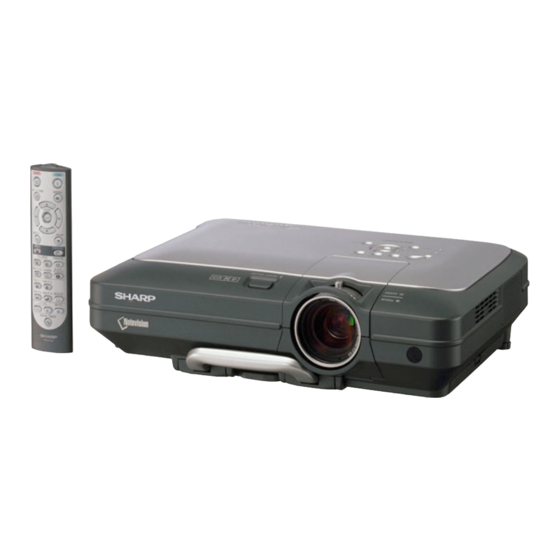
LCD PROJECTOR
LCD PROJEKTOR
PG-C45X
INHALT
WARTUNGSPERSONAL ................................ 49
DER OPTIK-EINHEIT ...................................... 59
Ë ELEKTRISCHE BAUTEILE ....................... 148
BAUTEILE ................................................. 164
Ë ZUBEHÖRTEILE ....................................... 169
Ë VERPACKUNGSTEILE ............................. 169
PG-C45X
SX2T3PG-C45X/
Seite
Inhaltsverzeichnis

Verwandte Anleitungen für Sharp PG-C45X


Inhaltszusammenfassung für Sharp PG-C45X
-
Seite 48: Technische Daten
*Bei vertikalen Frequenzen über 100 Hz kann eine zeitweise Störung sichtbar werden, wenn die OSD-Funktionen eingeschaltet sind. Dieser SHARP Projektor verwendet eine LCD (Liquid Crystal Display)-Anzeige.Diese hochmoderne Anzeige enthält 786.432 Pixel (xRGB) TFTs (Thin Film Transistors). Bei allen technologisch fortschrittlichen, elektronischen Geräten, z. B. Großbild-Fernsehern, Videosystemen bzw. Videokameras, sind bestimmte Toleranzgrenzen für die Funktionen gegeben. -
Seite 49: Hinweise Für Das Wartungspersonal
PG-C45X HINWEIS FÜR DAS WARTUNGSPERSONAL 1 2 3 4 5 6 7 8 9 0 1 2 3 4 5 6 7 8 9 0 1 2 3 4 5 6 7 8 9 0 1 2 1 2 3 4 5 6 7 8 9 0 1 2 3 4 5 1 2 3 4 5 6 7 8 9 0 1 2 3 4 5 6 7 8 9 0 1 2 3 4 5 6 7 8 9 0 1 2 1 2 3 4 5 6 7 8 9 0 1 2 3 4 5 Ë... -
Seite 50: Vorsichtsmaßregeln Für Bleifreien Lötzinn
PG-C45X Vorsichtsmaßregeln für bleifreien Lötzinn 1 Verwendung von bleifreiem Lötzinn Die "Eingangs-, Ausgangs-, Fernbedienungs-, Schlüsell-, Fächer-Platine" dieses Modells verwendet bleifreien Lötzinn. Das LF-Symbol zeigt bleifreien Lötzinn an und ist an den Platinen und Wartungsanleitungen angebracht. Der Buchstabe nach LF zeigt den Typ des bleifreien Lötzinns an. -
Seite 51: Bedienungsanleitung
PG-C45X Bedienungsanleitung Projektor (Vorder- und Draufsicht) Netz-Tasten(ON/OFF) INPUT-Taste Schaltet die Stromversorgung Für das Umschalten zwischen ein oder aus. Eingangsmodus 1, 2, 3 und 4. Netz-Anzeige KEYSTONE-Taste Leuchtet rot, wenn sich der Für das Einstellen der Projektor im Bereitschaftsbetrieb Trapezverzerrungs- oder Digitalen befindet. -
Seite 52: Projektor (Hintersicht)
PG-C45X Projektor (Hintersicht) USB-Anschluss AUDIO INPUT 1, 2- Anschluss Für den Anschluss eines Computers unter Geteilter Verwendung eines USB- Audioeingabeanschluss Kabels. für INPUT 1 und 2. WIRED REMOTE- RS-232C-Anschluss Eingabeanschluss Für die Bedienung des Projektors über Computers. INPUT 3-Anschluss Für den Anschluss eines AUDIO OUTPUT- Videogerätes. -
Seite 53: Fernbedienung (Draufsicht)
PG-C45X Fernbedienung (Vordersicht) KEYSTONE-Taste Netz-Tasten(ON/OFF) MENU-Taste ENTER-Taste Einstelltasten (', ", \, |) UNDO-Taste PinP-Taste ENLARGE-Tasten (Vergrößern/Verkleinern) FORWARD/BACK-Tasten GAMMA-Taste FREEZE-Taste BLACK SCREEN-Taste AUTO SYNC-Taste RESIZE-Taste INPUT-Tasten MUTE-Taste VOL-Tasten BREAK TIMER-Taste Fernbedienung (Draufsicht) WIRED R/C JACK Signalsender für Fernbedienung... -
Seite 54: Pin-Belegung
PG-C45X Pin-Belegung INPUT-1/2-RGB und OUTPUT-Signalanschluss: 15-Pin Mini-D-Sub weiblich RGB-Eingabe Komponenteneingabe 1. Videoeingabe (rot) 1. P 2. Videoausgabe (grün/sync auf grün) 2. Y 3. Videoausgabe (blau) 3. P 4. Reserveeingabe 1 4. Nicht angeschlossen 5. Composite-Sync 5. Nicht angeschlossen 6. Erde (rot) 6. -
Seite 55: Abmessungen
PG-C45X Abmessungen Einheiten: Zoll (mm) (1,5) (390) (1,5) 5 (126,5) ø 67,5 (80) (241,5) (100,5) (111,75) (75) (67,5) -
Seite 56: Ausbau Wichtiger Teile
PG-C45X AUSBAU WICHTIGER TEILE 1. Ausbau von Bodenfilter-Abdeckung und Lampeneinheit-Abdeckung 1-1. Bodenfilter-Abdeckung abtrennen. 1-2. Die Sperrschraube von der Lampeneinheit-Abdeckung lösen und die Lampeneinheit-Abdeckung abnehmen. 1-3. Den Tragegriff herausziehen. 1-4. Die mit * markierte Stelle auf der oberen Hälfte der Objektiv-Abdeckung drücken, um die Klaue zu lösen, und dann die obere Objektiv-Abdeckung entfernen. -
Seite 57: Entfernen Der Leiterplatten
PG-C45X 3. Entfernen der Leiterplatten 3-1. Die zwei Sperrschrauben vom Lampenfassung-Winkel entfernen. Den Lampenfassung-Winkel abtrennen. 3-2. Die Ballast-Einheit anheben. Den Steckverbinder abtrennen, und die Ballast-Einheit abtrennen. 3-3. Die Sperrschraube von der Leiterplatten-Einheit-Abdeckung lösen und die Abdeckung abnehmen. 3-4. Die drei Sperrschrauben vom Kühlgebläse entfernen, den Steckverbinder abtrennen, und die Leiterplatten- Baugruppe abnehmen. -
Seite 58: Rückstellung Deslampen-Timers
Die Lampe muss Restliche Lebensdauer der • Ersetzen Sie die Lampe. ausgetauscht Lampe sinkt auf 6% oder • Grün ein Den Projektor einem von Sharp autorisierten eingeschaltet werden weniger ab. Grün Händler für Projektoren oder dem Lampenaus- blinkt, Kundendienst zur Reparatur oder zum... -
Seite 59: Kurzbschreibung Der Optik-Einheit
PG-C45X KURZBESCHREIBUNG DER OPTIK-EINHEIT Layout für richtige Einrichtung der optischen Komponenten und Teile (Draufsicht) Projektionslinse Relaislinse 3 M5 Al-vergüteter Spiegel B M4 Al-vergüteter Spiegel R Fliegenauge-Objektiv (Ausgang) Fliegenauge-Objektiv (Eingang) Relaislinse 2 Reflektor G Reflektor R Reflektor B Relaislinse 1 Lichtquelle (Lampe) -
Seite 60: Einstellen Der Spiegel
PG-C45X Einstellen der Spiegel Diese Einstellung ist erforderlich, wenn optische Teile des Optik-Mechanismus ersetzt wurden. 1. Die Flachkabel von allen LCD-Platten abtrennen. 2. Die Lampe einschalten. 3. Ein Weißlichtbild projizieren und prüfen, ob ein Farbstich in einer Richtung vorhanden ist. Falls vorhanden, die Einstellhebel M2, M4 und M5 verwenden. -
Seite 61: Ersetzen Der Prismen-Einheit
PG-C45X Ersetzen der Prismen-Einheit 1. Die vier Sperrschrauben entfernen, und die Prismen-Einheit aus der Optik-Einheit nehmen. 2. Die Prismen-Einheit durch die neue ersetzen. Den obigen Schritt 1 in umgekehrter Reihenfolge ausführen. Hinweis: Auch wenn nur eine der LCD-Platten defekt ist, ist es erforderlich, die gesamte Prismen-Einheit zu ersetzen. -
Seite 62: Freigabe Der Systemsperre
PG-C45X Freigabe der Systemsperre Das Gerät einschalten. Wenn die Systemsperre aktiviert wird, erscheint die System-Nullstellungsanzeige. Danach sind die folgenden Tasten in der vorgeschriebenen Reihenfolge zu betätigen. MENU → ENTER → ENTER → MENU → UNDO → UNDO → MENU Zuerst die MENU-Taste drücken, dann die verbleibenden Tasten innerhalb von 10 Sekunden betätigen. -
Seite 63: Elektrisch Einstellung
PG-C45X ELEKTRISCHE EINSTELLUNG Einstellgegenstände Einstellbedingungen Einstellverfahren 1. Die folgenden Einstellungen vornehmen. Initialisieren von 1. Die S2601 drücken, um auf Prozessmodus zu EEPROM Betriebsstromversorgung schalten, und S2 im SSS-Menü einschalten (die Lampe ausführen. Jetzt ist der EEPROM, leuchtet auf), und das ausgenommen für die PC-... - Seite 64 PG-C45X Einstellgegenstände Einstellbedingungen Einstellverfahren Prüfen der 1. Das XGA-Mode 75-Hz 1. Den festen Wert prüfen. Abtasten-Halte- Schwarz-Signal Fester Wert: 6 Impulsphase einspeisen. 2. Die folgende Gruppe und die folgenden Gegenstände wählen. Gruppe: OUTPUT3 Gegenstand: GCK-PHASE Einstellung der 1. Das Gegenspannung- 1.
- Seite 65 PG-C45X Einstellgegenstände Einstellbedingungen Einstellverfahren Einstellung von 1. Das Teil-Farbbalken-Signal 1. Den festen Wert bestätigen. Video-Farbton einspeisen. Fester Wert: 128 2. Die folgende Gruppe und die folgenden Gegenstände wählen. Gruppe: VIDEO1 Gegenstand: TINT Einstellung von 1. Das Teil-Farbbalken-Signal 1. Den festen Wert bestätigen.
- Seite 66 PG-C45X Einstellgegenstände Einstellbedingungen Einstellverfahren Einstellung von 1. Das Y-0% Helligkeit, Cb und Cr 1. Das Signal einspeisen. Mit dem COMPO CB- 0% Weißmuster-Farbdifferenz- Steuerschalter am Gerät oder der Offset und CR- Signal (480I) einspeisen. betreffenden Taste an der Offset 2. Die folgende Gruppe und die Fernbedienung den Gegenstand folgenden Gegenstände wählen.
- Seite 67 PG-C45X Einstellgegenstände Einstellbedingungen Einstellverfahren Prüfen und 1. Die Einstellbedingungen für jeden 1. Sicherstellen, dass der Nachjustieren des Gegenstand sind wie folgt: Weißabgleich so ist, wie beim Weißabgleichs Für RGB-Eingang siehe Standardmonitor angegeben. Gegenstand 7. Nur Nachjustierung in der Für Video-Eingang siehe Reihenfolge RGB-Eingang, Video- Gegenstand 13.
-
Seite 68: Einstellung Der Pc-Schnittstelleneinheit
PG-C45X Einstellung der PC-Schnittstelleneinheit 1. Initialisieren von EEPROM 1) SW2801 drücken, um auf Prozessmodus zu schalten. 2) S1 im SSS-Menü ausführen. (Mit S1 wird die Platine alleine initialisiert. Nicht S2 ausführen, oder alle Justierdaten, ausgenommen die für PC-Schnittstelle, werden initialisiert. -
Seite 69: Eingabe Des Einstellprozeßmodus
PG-C45X » Eingabe des Einstellprozeßmodus Es gibt die folgenden zwei Verfahren. » Den SW2001 an der Ausgangs-Einheit drücken. » Die folgenden Tasten in der vorgeschriebenen Reihenfolge betätigen. Netz→Einstell oben→Einstell unten→Einstell oben→Einstell unten→ENTER→ENTER→MENU » Einstellmodus-Prozessmenü Gruppe Untergruppe Gegenstand Adjust PC Image... - Seite 70 PG-C45X Gruppe Untergruppe Gegenstand Process Mode LINE TEMP OFF SENSOR CHECK Initial Setting TIME Sample Pattern PATTERN RGB[50] CROSS FOCUS STEP COLOR Adjust CVIC CVIC PROGRESSIVE MODE MDSW PTGSW C-TESTSW C-ILG-LY C-MOD-LY C-VE-LV ENHANCE-VIDE ENH-PLUS ENH-MINUS ENHANCE-HDTV ENH-PLUS ENH-MINUS ENHANCE-RGB...
- Seite 71 PG-C45X Gruppe Untergruppe Gegenstand Adjust CVIC CMS-HUE CMS-HUE-R CMS-HUE-Y CMS-HUE-G CMS-HUE-C CMS-HUE-B CMS-HUE-M CMS-SAT CMS-SAT-R CMS-SAT-Y CMS-SAT-G CMS-SAT-C CMS-SAT-B CMS-SAT-M CMS-VAL CMS-VAL-R CMS-VAL-Y CMS-VAL-G CMS-VAL-C CMS-VAL-B CMS-VAL-M DEGAMMA Adust Digital Convergence CONVER R-CNV-H G-CNV-H B-CNV-H R-CNV-V G-CNV-V B-CNV-V Vesion Cehck etc...
-
Seite 72: Fehlersuchtabelle
PG-C45X FEHLERSUCHTABELLE Die Lampe leuchtet nicht auf. Netzschalter einschalten. Ist ein Ist die Lampe außerhalb der Die Lampe wieder in die Fassung Entladegeräusch von der Lampe Fassung? bringen. hörbar? Nein Nein Lampe wechseln. Nein Läuft das Ballast-Kühlgebläse? Die Betriebsstromkreise prüfen. - Seite 73 PG-C45X FEHLERSUCHTABELLE (Fortsetzung) Die Netzstufe prüfen. Nein Die Ausgang-Leiterplatteneinheit Kein Spannungsausgang an prüfen. CN708. Andere Welche Ausgangsspannungsleitung T703, IC703, IC705, IC706 und ihre ist nicht in Ordnung? Peripheriekreise prüfen. BU5.3V Nein Liegt AC-Spannung (90-264 V) CN701 oder Netz-kabel prüfen. über dem Stecker CN701 an? Liegt AC-Spannung (90-264 V) R775 ersetzen.
- Seite 74 PG-C45X FEHLERSUCHTABELLE (Fortsetzung) Kein Audio-Ausgang Nein Wird das Audio-Signal vom Emitter P301 und seine Peripheriekreise von Q306 ausgegeben? prüfen. Nein Wird das Signal an Stift (2) und (15) IC303 und seine Peripheriekreise von IC303 angelegt? prüfen. Wird das Signal an Stift (12) und (5)
- Seite 75 PG-C45X FEHLERSUCHTABELLE (Fortsetzung) Das Video-System prüfen. Nein Zu "Die Lampe leuchtet nicht auf" Leuchtet die Lampe? gehen. Nein Ist vorgeschriebene Spannung an Stromkreis und seine Teile prüfen. EA-Steckern? Nein Wird das Video-Signal an Stift (23) Den Videoanschluss und seine von P3102 angelegt? Peripheriekreise prüfen.
- Seite 76 PG-C45X FEHLERSUCHTABELLE (Fortsetzung) Prüfen des S-Video-Systems. Nein Zu "Die Lampe leuchtet nicht Leuchtet die Lampe? auf" gehen. Nein Ist vorgeschriebene Spannung an Stromkreis und seine Teile prüfen. EA-Steckern? Nein Wird das Video-Signal an Stift (19) Den Videoanschluss und seine und (21) von P3102 angelegt? Peripheriekreise prüfen.
- Seite 77 PG-C45X FEHLERSUCHTABELLE (Fortsetzung) Prüfen des RGB-Signals. Werden die RGB-Signale von Stift Nein IC3101 und seine Peripheriekreise (16), (18) und (20) von IC3101 prüfen. ausgegeben? Nein Werden die Signale von Stift (26), (28) SC3102 und P3102 und ihre und (30) von P3102 ausgegeben? Peripheriekreise prüfen.
- Seite 78 PG-C45X FEHLERSUCHTABELLE (Fortsetzung) Prüfen des RGB-Sync. Nein IC3152, IC3153, IC3154 und IC3151 Wird die Sync an Stift (2) und (4) und ihre Peripheriekreise prüfen. von SC3102 angelegt? Nein Werden die Signale an Stift (2), und P3102 und seine Peripheriekreise (12) von IC2404 angelegt? prüfen.
-
Seite 79: Fehlersuchtabelle Für Pc I/F Einheit
PG-C45X FEHLERSUCHTABELLE für PC I/F EINHEIT Überprüfen der PC-Platine Wird das Benutzermenü angezeigt? Nein Die Bildschirmanzeige überprüfen. Den RGB-Eingang überprüfen. Den Komponenteneingang überprüfen. Den Videoeingang überprüfen. Ende... - Seite 80 PG-C45X FEHLERSUCHTABELLE für PC I/F EINHEIT (Fortsetzung) Überprüfen der Bildschirmanzeige Wird das Benutzermenü Die Bildschirmanzeige ist normal. normalerweise durch die MENU- Taste angezeigt? Nein Das Prozeßmenü eingeben und PATTERN anwählen. Danach das COLOR-Muster wählen. Nein Die Farbe der Bildschirmanzeige Das DLP-System im Prozeß- normal? Einstellmodus einstellen.
- Seite 81 PG-C45X FEHLERSUCHTABELLE für PC I/F EINHEIT (Fortsetzung) Überprüfen des RGB-Eingangs Das RGB-Signal (Synchronisationstyp- Analogsignal) dem INPUT 1 zuführen. INPUT 1 mit der Gerätetaste bzw. mit der Fernbedienung anwählen. Nein Zu “Bestätigen des Erscheint das Bild? Videoeingangs” weitergehen. Zu “Überprüfen des Ist das Bild gestört?
- Seite 82 PG-C45X FEHLERSUCHTABELLE für PC I/F EINHEIT (Fortsetzung) Bestätigung des Videoeingangs “Bestätigung der Eingangssignal- Einstellung” vornehmen. Nein Nein Liegt am stift (55) von SC8002 Liegt am C8070 ein Videosignal (B-to-Bker) ein Signal an? vor? Defekt innerhalb des Zu “Überprüfen des Synchronisationssignals”...
- Seite 83 PG-C45X FEHLERSUCHTABELLE für PC I/F EINHEIT (Fortsetzung) Überprüfen des Synchronisationssignals Liegt am Stift (11) von IC8363 ein Nein Vertikal- Synchronisationssignal Liegt am Stift (5) von IC8363 ein Nein Bestätigung der Eingangssignal- Horizontal- Synchronisationssignal Einstellung vornehmen. R997, R996, SC8002 oder ihre zugehörigen Komponenten sind...
- Seite 84 PG-C45X FEHLERSUCHTABELLE für PC I/F EINHEIT (Fortsetzung) Überprüfen der R-, G- und B- Signale Ist der Signaltyp auf RGB Nein eingestellt? Den Signaltyp auf RGB einstellen. Den Prozeßmodus einstellen. R, G und B einzeln auf dem Mustermenü anwählen. Zu “Überprüfen von GA4 und seine zugehörigen Komponenten”...
- Seite 85 PG-C45X FEHLERSUCHTABELLE für PC I/F EINHEIT (Fortsetzung) Überprüfen von GA4 und seine zugehörigen Komponenten R, G und B einzeln auf dem Mustermenü anwählen. Das Überprüfen von GA4 und der Wird das Bild korrekt in R-, G- zugehörigen Komponenten ist und B-Signalen ausgegeben? beendet.
- Seite 86 PG-C45X FEHLERSUCHTABELLE für PC I/F EINHEIT (Fortsetzung) Überprüfen des Komponenteneingangs (außer 480I) Das Komponentensignal dem INPUT 1 zuführen. INPUT 1 mit der Gerätetaste bzw. mit der Fernbedienung anwählen. Nein Zu “Überprüfen des SOG- Erscheint das Bild? Schaltkreises” weitergehen. Ist die Farbe normal?
- Seite 87 PG-C45X FEHLERSUCHTABELLE für PC I/F EINHEIT (Fortsetzung) Überprüfen des SOG-Schaltkreises Den Stift (2) von IC8365 mit dem Oszilloskop überprüfen. Wird das Farbbildsignal mit dem Der SOG-Schaltkreis ist normal. korrekten Timing reproduziert? Ende. Nein C8070 mit dem Oszilloskop überprüfen. Nein Zu “Bestätigung der Liegt ein Y-Signal (einschl.
- Seite 88 PG-C45X FEHLERSUCHTABELLE für PC I/F EINHEIT (Fortsetzung) Überprüfen des Videoeingangs Das Farbbildsignal dem INPUT 3 zuführen. INPUT 1 mit der Gerätetaste bzw. mit der Fernbedienung anwählen. Nein Zu “Überprüfen des Video- Erscheint das Bild? Synchronsignals” weitergehen. Bestehen irgendwelche Bildstörungen? Nein Zu “Überprüfen des Video-...
- Seite 89 PG-C45X FEHLERSUCHTABELLE für PC I/F EINHEIT (Fortsetzung) Überprüfen des Video- Synchronsignals Den Stift (10) von IC8363 mit dem Oszilloskop überprüfen. (Überprüfen des Vertikal-Synchronsignals) Nein Ist das Vertikal-Synchronsignal normal? Den Stift (6) von IC8363 mit dem Oszilloskop überprüfen. (Überprüfen des Vertikal-...
-
Seite 90: Chassis Layout
PG-C45X CHASSIS LAYOUT/CHASSIS-ANORDNUNG... - Seite 91 PG-C45X...
-
Seite 92: Block Diagram
PG-C45X BLOCK DIAGRAM/BLOCKCHALTBILD... - Seite 93 PG-C45X...
-
Seite 94: Overall Wiring Diagram
PG-C45X OVERALL WIRING DIAGRAM/GESAMTSCHALTPLAN... - Seite 95 PG-C45X...
-
Seite 96: Description Of Schematic Diagram
PG-C45X DESCRIPTION OF SCHEMATIC BESCHREIBUNG DES DIAGRAM SCHEMATISCHEN SCHALTPLANS VOLTAGE MEASUREMENT CONDITION: SPANNUNGSMESSUNGEN: 1. Spannungen an den Prüfpunkten werden bei einer 1. Voltages at test points are measured at the supply Netzspannung von 230V gemessen, Signale werden voltage of AC 230V. Signals are fed by a colour bar für die Wartung mit einem Farbbalken-Signal... -
Seite 97: Ë R/C Receiver Unit / Fernbedienungs-Einheit
PG-C45X Ë R/C RECEIVER UNIT / FERNBEDIENUNGS-EINHEIT... -
Seite 98: Ë Input Unit-1/2 / Eingangs Einheit-1
PG-C45X Ë INPUT UNIT-1/2 / EINGANGS EINHEIT-1/2... - Seite 99 PG-C45X...
-
Seite 100: Ë Input Unit-2/2 / Eingangs Einheit-2
PG-C45X Ë INPUT UNIT-2/2 / EINGANGS EINHEIT-2/2... - Seite 101 PG-C45X...
-
Seite 102: Ë Output Unit-1/8 / Ausgangseinheit-1
PG-C45X Ë OUTPUT UNIT-1/8 / AUSGANGSEINHEIT-1/8... - Seite 103 PG-C45X...
-
Seite 104: Ë Output Unit-2/8 / Ausgangseinheit-2
PG-C45X Ë OUTPUT UNIT-2/8 / AUSGANGSEINHEIT-2/8... - Seite 105 PG-C45X...
-
Seite 106: Ë Output Unit-3/8 / Ausgangseinheit-3
PG-C45X Ë OUTPUT UNIT-3/8 / AUSGANGSEINHEIT-3/8... - Seite 107 PG-C45X...
-
Seite 108: Ë Output Unit-4/8 / Ausgangseinheit-4
PG-C45X Ë OUTPUT UNIT-4/8 / AUSGANGSEINHEIT-4/8... - Seite 109 PG-C45X...
-
Seite 110: Ë Output Unit-5/8 / Ausgangseinheit-5
PG-C45X Ë OUTPUT UNIT-5/8 / AUSGANGSEINHEIT-5/8... - Seite 111 PG-C45X...
-
Seite 112: Ë Output Unit-6/8 / Ausgangseinheit-6
PG-C45X Ë OUTPUT UNIT-6/8 / AUSGANGSEINHEIT-6/8... - Seite 113 PG-C45X...
-
Seite 114: Ë Output Unit-7/8 / Ausgangseinheit-7
PG-C45X Ë OUTPUT UNIT-7/8 / AUSGANGSEINHEIT-7/8... - Seite 115 PG-C45X...
-
Seite 116: Ë Output Unit-8/8 / Ausgangseinheit-8
PG-C45X Ë OUTPUT UNIT-8/8 / AUSGANGSEINHEIT-8/8... - Seite 117 PG-C45X...
-
Seite 118: Ë Key Unit / Schlüsseleinheit
PG-C45X Ë KEY UNIT / SCHLÜSSELEINHEIT... - Seite 119 PG-C45X...
-
Seite 120: Ë Fan Unit / Gebläse-Hinheit
PG-C45X Ë FAN UNIT / GEBLÄSE-HINHEIT... - Seite 121 PG-C45X...
-
Seite 122: Ë Ac Inlet And Power Unit / Ac Eingangs-Und Netz-Einheit
PG-C45X Ë AC INLET and POWER UNIT / AC EINGANGS-und NETZ-EINHEIT... - Seite 123 PG-C45X...
- Seite 124 PG-C45X Ë PC I/F UNIT-1/7 / PC-I/F-EINHEIT-1/7...
- Seite 125 PG-C45X...
- Seite 126 PG-C45X Ë PC I/F UNIT-2/7 / PC-I/F-EINHEIT-2/7...
- Seite 127 PG-C45X...
- Seite 128 PG-C45X Ë PC I/F UNIT-3/7 / PC-I/F-EINHEIT-3/7...
- Seite 129 PG-C45X...
- Seite 130 PG-C45X Ë PC I/F UNIT-4/7 / PC-I/F-EINHEIT-4/7...
- Seite 131 PG-C45X...
- Seite 132 PG-C45X Ë PC I/F UNIT-5/7 / PC-I/F-EINHEIT-5/7...
- Seite 133 PG-C45X...
- Seite 134 PG-C45X Ë PC I/F UNIT-6/7 / PC-I/F-EINHEIT-6/7...
- Seite 135 PG-C45X...
- Seite 136 PG-C45X Ë PC I/F UNIT-7/7 / PC-I/F-EINHEIT-7/7...
- Seite 137 PG-C45X...
-
Seite 138: Printed Wiring Board Assemblies
PG-C45X PRINTED WIRING BOARD ASSEMBLIES LEITERPLATTENINHEITIN POWER Unit (Side-A) NETZ-Einheit (Seite-A) - Seite 139 PG-C45X POWER Unit (Side-B) NETZ-Einheit (Seite-B)
- Seite 140 PG-C45X INPUT Unit (Side-A) EINGANGS-Einheit (Seite-A)
- Seite 141 PG-C45X INPUT Unit (Side-B) EINGANGS-Einheit (Seite-B)
- Seite 142 PG-C45X OUTPUT Unit (Side-A) AUSGANGS-Einheit (Seite-A)
- Seite 143 PG-C45X OUTPUT Unit (Side-B) AUSGANGS-Einheit (Seite-B)
- Seite 144 PG-C45X PC I/F Unit (Side-A) PC I/F-Einheit (Seite-A)
- Seite 145 PG-C45X PC I/F Unit (Side-B) PC I/F-Einheit (Seite-B)
- Seite 147 PG-C45X FAN Unit (Side-A) GEBLÄSE-Einheit (Seite-A) FAN Unit (Side-B) GEBLÄSE-Einheit (Seite-B)
-
Seite 148: Parts Listë Electrical Parts
Contact your nearest SHARP Parts Distributor. For location of SHARP Parts Distributor, 5. KODE 6. QUANTITÄT Please call Toll-Free; 1-800-BE-SHARP in CANADA: Contact SHARP Electronics of Canada Limited Phone (416) 890-2100. MARK: SPARE PARTS-DELIVERY SECTION MARKIERUNG : ERSATZTEILE-LIEFERUNG Ref. No. -
Seite 164: Ë Cabinet And Mechanical Parts
PG-C45X CABINET AND MECHANICAL PARTS 6-1-2 6-1-4 2-1-6 6-1-1 2-1-1 6-1-5 2-1-4 6-1-3 1-1-5 6-1-6 1-1-2 1-1-4 1-1-3 2-1-3 2-1-5 2-1-2 2-1-5-3 2-1-5-4 2-1-2 2-1-5-1 1-1-1 2-1-5-2 2-1-7 3-18 3-22 3-21 3-27 3-26 3-27 3-12 3-11 3-14 3-27 3-23 3-1-8... - Seite 166 PG-C45X OPTICS MECHANISM PARTS-1/2 5-2-7 5-2-6 5-2-6 5-2-7 5-2-6 5-2-1 5-2-5 5-2-2 5-2-6 5-2-7 5-2-3 5-2-6 5-1-15 5-2-4 5-1-16 5-2-2 5-2-1 5-2-7 5-2-7 5-1-4 5-1-1 5-1-2 5-1-17 5-1-12 5-1-14 5-1-11 5-3-1-14 5-3-1-16 5-3-1-1 5-3-1-10 5-3-1-15 5-3-1-1 5-3-1-1 5-3-1-9 5-3-1-12 5-3-1-9...
- Seite 167 PG-C45X OPTICS MECHANISM PARTS-2/2 5-4-6 5-4-2 5-4-9 5-4-1 5-4-8 5-4-9 5-4-1-4 5-4-1-1 5-4-7 5-4-10 5-4-9 5-4-5 5-4-1-1 5-45 5-4-3 5-4-5 5-4-1-3 5-4-8 5-4-1-2 5-4-1-4 5-45 5-45 5-45 5-11 5-46 5-45 5-11 5-45 5-36 5-16 5-43 5-12 5-12 5-34 5-45 5-36...
- Seite 171 PG-C45X...
- Seite 172 PG-C45X COPYRIGHT © 2002 BY SHARP CORPORATION ALL RIGHTS RESERVED. No part of this publication may be reproduced, stored in a retrieval system, or transmitted in any form or by any means, electronic, mechanical, photocopying, recording, or otherwise, without prior written permission of the publisher.