HomeMatic HM-LC-Sw1-SM, HM-LC-Sw4-SM Installations- Und Bedienungsanleitung
Schalt-/jalousie-/dimmaktoren aufputzmontage
Vorschau ausblenden
Andere Handbücher für HM-LC-Sw1-SM, HM-LC-Sw4-SM:
- Bedienungsanleitung (31 Seiten) ,
- Installations- und bedienungsanleitung (60 Seiten) ,
- Installations- und bedienungsanleitung (59 Seiten)
Inhaltsverzeichnis
Werbung
Verfügbare Sprachen
Verfügbare Sprachen
Quicklinks
Installations- und
D
Bedienungsanleitung
Schalt-/Jalousie-/Dimmaktoren
Aufputzmontage:
HM-LC-Sw1-SM, HM-LC-Sw4-SM
HM-LC-Bl1-SM, HM-LC-Dim2L-SM
Seite 4 - 29
Installation and
GB
Operating Manual
Switch-/blind-/diming actuators
surface-mount:
HM-LC-Sw1-SM, HM-LC-Sw4-SM
HM-LC-Bl1-SM, HM-LC-Dim2L-SM
Page 30 - 56
Werbung
Kapitel
Inhaltsverzeichnis

Verwandte Anleitungen für HomeMatic HM-LC-Sw1-SM, HM-LC-Sw4-SM


Inhaltszusammenfassung für HomeMatic HM-LC-Sw1-SM, HM-LC-Sw4-SM
- Seite 1 Installations- und Bedienungsanleitung Schalt-/Jalousie-/Dimmaktoren Aufputzmontage: HM-LC-Sw1-SM, HM-LC-Sw4-SM HM-LC-Bl1-SM, HM-LC-Dim2L-SM Seite 4 - 29 Installation and Operating Manual Switch-/blind-/diming actuators surface-mount: HM-LC-Sw1-SM, HM-LC-Sw4-SM HM-LC-Bl1-SM, HM-LC-Dim2L-SM Page 30 - 56...
- Seite 2 3. Ausgabe Deutsch 04/2008 Dokumentation © 2007 eQ-3 Ltd., Hong Kong Alle Rechte vorbehalten. Ohne schriftliche Zustimmung des Herausgebers darf dieses Handbuch auch nicht auszugsweise in irgendeiner Form reproduziert werden oder unter Verwendung elektronischer, mechanischer oder chemischer Verfahren vervielfältigt oder verarbeitet werden. Es ist möglich, dass das vorliegende Handbuch noch drucktechnische Mängel oder Druckfehler aufweist.
- Seite 3 3rd English edition 04/2008 Documentation © 2007 eQ-3 Ltd. Hong Kong All rights reserved. No parts of this manual may be reproduced or processed in any form using electronic, mechanical or chemical processes in part or in full without the prior explicit written permission of the publisher.
-
Seite 4: Inhaltsverzeichnis
Allgemeine Systeminformation zu HomeMatic ......13 Allgemeine Hinweise zum Funkbetrieb ..13 Installation . -
Seite 5: Hinweise Zu Dieser Anleitung
Hinweise zu dieser Anleitung Lesen Sie diese Anleitung sorgfältig, bevor Sie ihre HomeMatic Komponenten in Betrieb nehmen. Bewahren Sie die Anleitung zum späteren Nachschlagen auf! Wenn Sie das Gerät anderen Personen zur Nutzung überlassen, übergeben Sie auch diese Bedienungsanleitung. Benutzte Symbole: Achtung! Hier wird auf eine Gefahr hingewiesen. - Seite 6 Der Betrieb des Gerätes ist ausschließlich am 230V/50Hz-Wechselspannungsnetz zulässig. Arbeiten am 230V-Netz dürfen nur von einer Elektro- Fachkraft (nach VDE 0100) erfolgen. Dabei sind die geltenden Unfallverhütungsvorschriften zu beachten. Zur Vermeidung eines elektrischen Schlages vor Arbeiten am Gerät Netzspannung freischalten (Sicherungsautomat abschalten).
- Seite 7 Schaltaktor: Beachten Sie vor Anschluss eines Verbrauchers unbedingt die technischen Daten, insbesondere die maximal zulässige Schaltleistung des Relais und Art des anzuschließenden Verbrauchers! Alle Lastangaben beziehen sich auf ohmsche Lasten! Jalousieaktor: Der Aktor ist nur für 230V Wechselstrommotoren geeignet! Schließen Sie keine Drehstrommotoren und keine Gleichstrommotoren an! Sollen am Ausgang des Aktors Motoren parallel geschaltet werden, beachten Sie unbedingt die...
-
Seite 8: Funktion
Dimmaktor: Unbedingt auf die angeschlossene Last achten! Der Dimmer ist nur für Glühlampen und für NV- Halogenlampen mit konventionellen Trafos geeignet! Die Geräte sind nicht zum Freischalten geeignet. Die Last ist nicht galvanisch vom Netz getrennt. Bei Betrieb mit konventionellen Trafos jeden Trafo entsprechend Herstellerangabe primärseitig absichern. - Seite 9 HM-LC-Sw1-SM Kanal-LED Verschraubungen für Anschlussleitung Power-LED Kanal-Taste...
- Seite 10 HM-LC-Sw4-SM Kanal-LED Verschraubungen für Anschlussleitung Power-LED Kanal-Taste...
- Seite 11 HM-LC-Bl1-SM Kanal-LED (AUF/AB) Verschraubungen für Anschlussleitung Power-LED Kanal-Taste (AUF/AB)
- Seite 12 HM-LC-Dim2L-SM Kanal-LED Verschraubungen für Anschlussleitung Kanal-Taste Kühlkörper...
-
Seite 13: Allgemeine Systeminformation Zu Homematic
Allgemeine Systeminformation zu HomeMatic Dieses Gerät ist Teil des HomeMatic Haussteuersystems und arbeitet mit dem ® bidirektionalen BidCoS Funkprotokoll. Alle Geräte werden mit einer Standardkonfiguration ausgeliefert. Darüber hinaus ist die Funktion des Gerätes über ein Programmiergerät und Software konfigurierbar. Welcher weitergehende... - Seite 14 Luftfeuchtigkeit neben baulichen Gegebenheiten vor Ort eine wichtige Rolle. Hiermit erklärt die eQ-3 Entwicklung GmbH, dass sich dieses Gerät in Übereinstimmung mit den grundlegenden Anforderungen und den anderen relevanten Vorschriften der Richtlinie 1999/5/EG befindet. Die vollständige Konformitätserklärung finden Sie unter www.HomeMatic.com.
-
Seite 15: Installation
Installation Die Aktoren zur Aufputzmontage eignen sich wegen ihrer erhöhten Schutzart zur Montage im Außenbereich und in Feuchträumen. Zur Montage und Installation entfernen Sie den transparenten Gehäusedeckel. Darunter sind die Bohrungen zur Wandbefestigung sichtbar. Um an die Anschlussklemmen zu gelangen entfernen Sie die graue Abdeckplatte. - Seite 16 HM-LC-Sw1-SM Anschluss Außenleiter Anschluss Neutralleiter Anschluss PE Geschaltete Phase (Wechselrelais Pos. 1) Geschaltete Phase (Wechselrelais Pos. 2) Anschluss Außenleiter...
- Seite 17 HM-LC-Sw4-SM Anschluss Außenleiter Anschluss Neutralleiter Anschluss PE Geschaltete Phase (Wechselrelais Pos. 1) Geschaltete Phase (Wechselrelais Pos. 2) Anschluss Außenleiter...
- Seite 18 HM-LC-Bl1-SM Anschluss Außenleiter Anschluss PE Anschluss Neutralleiter Anschluss Außenleiter (Geräteversorgung) Durchgeschleifte Phase im Gerät zum Ansteuern der Tastereingänge Eingang für Taster (Phase) „AUF“ Eingang für Taster (Phase) „AB“ Geschaltete Phase „AB“ Anschluss Außenleiter (Motorversorgung) Geschaltete Phase „AUF“...
- Seite 19 HM-LC-Dim2L-SM Anschluss Außenleiter Anschluss Neutralleiter Anschluss PE Gedimmte Phase Kanal 1 Neutralleiter Kanal 1 Gedimmte Phase Kanal 2 Neutralleiter Kanal 2...
- Seite 20 Zugelassene Leitungsquerschnitte zum Anschluss an die AP-Aktoren: starre flexible flexible Leitung Leitung ohne Leitung mit Aderendhülse Aderendhülse 0,50 – 2,50 0,50 - 2,50 0,50 – 2,50...
-
Seite 21: Inbetriebnahme
Inbetriebnahme 7.1 Einfache Bedienfunktionen am Gerät An den Geräten ist pro Kanal ein Bedientaster (beim Jalousieaktor jeweils ein Taster für AUF und für AB). Sie können den Aktor über diese sofort bedienen (Anlernen nicht erforderlich) und die korrekte elektrische Installation überprüfen. Bei den Schalt- und Dimmakoren können Sie den Kanal damit an- und ausschalten. - Seite 22 Die Aufputz-Schaltaktoren besitzen keine spezielle Anlerntaste. Zum Anlernen an einen bestimmten Kanal des Aktors halten Sie die zugehörige Kanaltaste (beim Jalousieaktor eine der beiden Tasten oder ) für etwa 4 Sekunden lang gedrückt. Dauerhaftes Blinken der Geräte-LED signalisiert den Anlernmodus. Wenn kein Anlernen erfolgt, wird der Anlernmodus automatisch nach 20 Sekunden beendet.
-
Seite 23: Bedienung
Bedienung Nach dem Anlernen stehen einfache Bedienfunktionen über die angelernten Bedienelemente zur Verfügung. 8.1 Schaltaktoren Je nach angelerntem Bedienelement lässt sich der Schaltaktor im Zweitasten-AN/AUS-Betrieb oder im Toggle-Bertrieb ansteuern. 8.2 Jalousieaktor Je nach angelerntem Bedienelement lässt sich der Jalousieaktor im Zweitasten-AUF/AB-Betrieb oder im Toggle-Bertrieb (AUF/STOPP/AB/STOPP) ansteuern. -
Seite 24: Zurücksetzen In Den Auslieferungszustand
Zurücksetzen in den Auslieferungszustand Um den Aktor in den Auslieferungszustand zurückzusetzen versetzen Sie das Gerät über die (erste) Kanaltaste in den Anlernmodus (mindestens 4 Sekunden Taste gedrückt halten). Befindet sich das Gerät im Anlernmodus, halten Sie erneut die (erste) Kanaltaste für mindestens 4 Sekunden gedrückt. -
Seite 25: Anzeige Des Betriebszustandes
10.2 Anzeige des Betriebszustandes Sobald das Relais eines Kanals (bzw. beim Jalousieaktor eine Richtung) angezogen ist, leuchtet die entsprechende Kanal-LED dauerhaft. Nach Konfiguration des Aktors über die Zentrale oder über ein Programmiertool zeigt die Geräte- LED neben den beschriebenen noch zusätzliche Zustände des Geräts an. - Seite 26 Sollte der Test ohne Fehler durchlaufen, sendet der Aktor ein Funktelegramm mit seiner Statusinformation aus. Damit bei Spannungswiederkehr (etwa nach Netzspannungsausfall oder Abschaltung) nicht alle Aktoren gleichzeitig senden, wartet der Aktor eine zufällige Verzögerungszeit vor dem Senden. In dieser Zeit blinken die Kanal-LEDs (wie im Anlernmodus).
-
Seite 27: Wartung Und Reinigung
12 Wartung und Reinigung Das Produkt ist wartungsfrei. Überlassen Sie eine Reparatur einer Fachkraft. Dimmaktor Das Gerät enthält zwei interne Gerätesicherungen zum Schutz der Triacs vor zu großer Strombelastung. Sollte das Gerät überlastet werden und eine Sicherung auslösen kann sie von einem Fachmann ersetzt werden! Vor Ausbau des Gerätes unbedingt Netz- spannung freischalten (Sicherungsautomat... -
Seite 28: Technische Daten
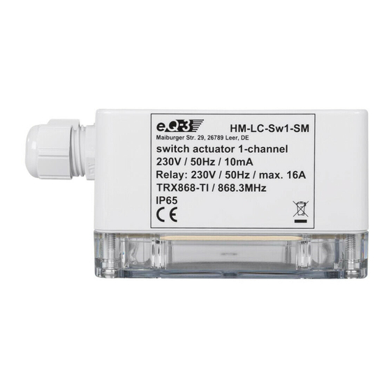
13 Technische Daten Funkfrequenz: 868,3 MHz Typ. Freifeldreichweite: 300 m Spannungsversorgung: 230 V / 50 Hz Standby-Verbrauch: 0,5 W (Dimmer 0,8 W) Schutzart: IP65 Schutzklasse: Gehäuse: Gehäusefarbe: Lichtgrau HM-LC-Sw1-SM Relais: Wechsler (potentialfreier Kontakt) Schaltvermögen: 16 A (ohmsche Last) Abmessungen: 90 x 115 x 55 mm (H x B x T) HM-LC-Sw4-SM Relais:... - Seite 29 HM-LC-Bl1-SM Relais: 1 Schliesser, 1 Wechsler (potentialfreie Kontakte) Schaltvermögen: 16 A (ohmsche Last), 800 W Motorlast Abmessungen: 115 x 160 x 55 mm (H x B x T) HM-LC-Dim2L-SM Anschlussleistung: 25–500 VA Abmessungen: 121 x 171 x 55 mm (H x B x T) Entsorgungshinweis Gerät nicht im Hausmüll entsorgen! Elektronische Geräte sind entsprechend...
- Seite 30 Function......34 General system information on HomeMatic 39 General information on radio operation ..39 Installation .
-
Seite 31: Information Concerning These Instructions
Information concerning these instructions Read these instructions carefully before beginning operation with your HomeMatic components. Keep the instructions handy for later consultation! Please hand-over the operating manual as well when you hand-over the device to other persons for use. Symbols used: Attention! This indicates a hazard. - Seite 32 Operating the device is only permitted with a 230 V/50 Hz alternating current network. Work on the 230 V network is only permitted by qualified electricians (in accordance with VDE 0100). Always observe the applicable accident prevention regulations. Disconnect the power to devices before working on them to prevent electrocution (switch circuit breaker).
- Seite 33 Switch actuator: Follow all technical specifications, especially the maximum permitted switching capacity of the relay and type of consumer to be connected, before connecting the consumer! All load specifications refer to resistive loads! Blind actuator: The actuator is only suitable for 230V a.c. motors! Never connect three-phase a.c.
-
Seite 34: Function
Dimming actuator: Make sure to observe the applied load! The dimmer is only suitable for light bulbs and for low voltage NV halogen lamps with magnetic transformers! The devices are not intended to be isolated. The load is not electrically isolated from the mains. Fuse every transformer on the primary side according to the manufacturer‘s specifications when working with conventional transformers. - Seite 35 HM-LC-Sw1-SM Channel LED Connecting wire terminals Power LED Channel button...
- Seite 36 HM-LC-Sw4-SM Channel LED Connecting wire terminals Power LED Channel button...
- Seite 37 HM-LC-Bl1-SM Channel LED (UP/DOWN) Connecting wire terminals Power LED Channel button (UP/DOWN)
- Seite 38 HM-LC-Dim2L-SM Channel LED Connecting wire terminals Channel button Cooler...
-
Seite 39: General System Information On Homematic
General system information on HomeMatic This device is a part of the HomeMatic home control ® system and works with the bidirectional BidCoS wireless protocol. All devices are delivered in a standard configuration. The functionality of the device can also be configured with a programming device and software. - Seite 40 Hereby eQ-3 Entwicklung GmbH, declares that this device conforms with the essential require- ments and other relevant regulations of Directive 1999/5/EC. The full declaration of conformity is provided under www.HomeMatic.com.
-
Seite 41: Installation
Installation The surface-mount actuators are suitable for installing outdoors and in humid rooms because of the increased degree of protection. Remove the transparent housing cover for mounting and installing. The holes for fastening to the wall are visible underneath. In order to access the connection terminals, remove the gray cover plate. - Seite 42 HM-LC-Sw1-SM External conductor connection Neutral connection PE connection Switched channel (change-over relay Item 1) Switched channel (change-over relay Item 2) External conductor connection...
- Seite 43 HM-LC-Sw4-SM External conductor connection Neutral connection PE connection Switched channel (change-over relay Item 1) Switched channel (change-over relay Item 2) External conductor connection...
- Seite 44 HM-LC-Bl1-SM External conductor connection PE connection Neutral connection External conductor connection (device supply) Looped channel in device for controlling button inputs Button input (Channel) "UP" Button input (Channel) "DOWN" Switched channel "DOWN" External conductor connection (motor supply) Switched channel "UP"...
- Seite 45 HM-LC-Dim2L-SM External conductor connection Neutral connection PE connection Dimmed phase channel 1 Neutral line channel 1 Dimmed phase channel 2 Neutral line channel 2...
- Seite 46 Permitted wire cross-section for connecting to the AP actuators: Rigid wire Flexible wire Flexible wire without end with end sleeve [mm sleeve [mm 0.50 – 2.50 0.50 - 2.50 0.50 – 2.50...
-
Seite 47: Start Up
Start up 7.1 Simple operating functions on the device There is one control button per channel on the devices (one UP button and one DOWN button for the blind actuator). You can operate the actuator immediately (teaching is not required) and check for correct electrical installation. - Seite 48 The surface-mount actuators have no special teach button.Teaching a certain actuator channel requires pressing and holding the respective channel button (one of the two buttons for the blind actuators). Teach mode is indicated by the device LED flashing continuously. If no teaching occurs, teach mode is automatically ended after 20 seconds.
-
Seite 49: Operation
Operation After teaching, simple operating functions are available using the taught control elements. 8.1 Switching actuators Depending on the control elements that have been taught, the switch actuator can be controlled in two button ON/OFF mode or in toggle mode. 8.2 Blind actuator Depending on the control elements that have been taught, the blind actuator can be controlled in two... -
Seite 50: Resetting To Factory Status
Resetting to factory status In order to reset the actuator to factory status, switch the device to teach mode with the (first) channel button (hold button pressed for at least 4 seconds). If the device is in teach mode, hold the (first) channel button pressed down for at least 4 seconds. -
Seite 51: Operational Status Display
10.2 Operational status display As soon as the relay for a channel (or a direction for the blind actuator) is triggered, the respective channel LED will be illuminated continuously. After configuring the actuator with the center or a programming tool, the device LED indicates other device states besides those described. - Seite 52 at the same time when the power returns (after a power outage or shut-down). During this time, the channel LEDs flash (like in teach mode). If the delay time is short, the flashing may not even be noticeable.
-
Seite 53: Maintenance And Cleaning
12 Maintenance and cleaning This product is maintenance-free. Repairs are only to be done by trained professionals. Dimming actuator The device is provided with two internal device fuses for protecting the triac from greater current loads. If the device becomes overloaded and a fuse is blown, it can be replaced by a technician! Disconnect the mains power before removing... -
Seite 54: Technical Specifications
13 Technical specifications Radio frequency: 868.3 MHz Typ. outdoor range: 300 m Power supply: 230 V / 50 Hz Standby consumption: 0.5 W (dimmer 0,8 W) Degree of protection: IP65 Protection class: Housing: Housing color: Light gray HM-LC-Sw1-SM Relay: Change-over (potential-free contacts) Switching capacity: 16 A (resistive load) - Seite 55 HM-LC-Bl1-SMRelay: 1 normally open, 1 change-over (potential-free contacts) Switching capacity: 16 A (resistive load), 800 W motor load Dimensions: 115 x 160 x 55 mm (H x W x D) HM-LC-Dim2L-SM Connection power: 25–500 VA Dimensions: 121 x 171 x 55 mm (H x W x D)
- Seite 56 Instructions for disposal Do not dispose off the device as part of household garbage! Electronic devices are to be disposed ofin accordance with the guidelines concerning electrical and electronic devices via the local collecting point for old electronic devices. The CE sign is a free trade sign addressed exclusively to the authorities and does not include any warranty of any properties.
- Seite 58 eQ-3 AG Maiburger Straße 29 D-26789 Leer www.eQ-3.com...