Grundig M 19-C Bedienungsanleitung
Inhaltsverzeichnis
Service Manual
Grundig Service
Hotline Deutschland...
...Mo.-Fr. 8.00-18.00 Uhr
Technik:
TV
0180/52318-41
TV
0180/52318-49
SAT
0180/52318-48
VCR/LiveCam
0180/52318-42
HiFi/Audio
0180/52318-43
Car Audio
0180/52318-44
Telekommunikation
0180/52318-45
Fax:
0180/52318-51
Planatron
0180/52318-99
(8.00-22.00 Uhr)
Ersatzteil-Verkauf:
...Mo.-Fr. 8.00-19.00 Uhr
Telefon:
0180/52318-40
Fax:
0180/52318-50
Zusätzlich erforderliche
Unterlagen für den Komplettservice
Additionally required
Service Manuals for the Complete Service
Service
Service
Manual
Manual
Sicherheit
M 19-C
M 29-C
Safety
Materialnr./Part No.
Materialnr./Part No.
72010 759 1500
72010 800 0000
HiFi
M 19-C
(
)
G.LI 0451
M 29-C
(
)
G.LI 0551
Btx * 32700 #
Materialnummer
Part Number 72010 759 1500
Änderungen vorbehalten
Subject to alteration
Printed in Germany
VK232 0199
Inhaltsverzeichnis

Verwandte Anleitungen für Grundig M 19-C


Inhaltszusammenfassung für Grundig M 19-C
- Seite 1 Service Manual HiFi Grundig Service Hotline Deutschland..Mo.-Fr. 8.00-18.00 Uhr M 19-C Technik: 0180/52318-41 G.LI 0451 0180/52318-49 M 29-C 0180/52318-48 VCR/LiveCam 0180/52318-42 G.LI 0551 HiFi/Audio 0180/52318-43 Car Audio 0180/52318-44 Telekommunikation 0180/52318-45 Fax: 0180/52318-51 Planatron 0180/52318-99 (8.00-22.00 Uhr) Ersatzteil-Verkauf: ...Mo.-Fr. 8.00-19.00 Uhr...
-
Seite 2: Inhaltsverzeichnis
Während der Umstellphase können im Service Manual beide the Service Manual. Schreibweisen vorkommen. Test Equipment Meßgeräte Please note the GRUNDIG Catalog "Test and Measuring Equipment" Beachten Sie bitte das GRUNDIG Meßtechnik-Programm, das Sie obtainable from: unter folgender Adresse erhalten: Grundig AG Geschäftsbereich Instruments Test- und Meßsysteme Würzburger Str. -
Seite 3: Allgemeiner Teil
M 19-C / M 29-C Allgemeiner Teil / General Section Allgemeiner Teil General Section Technische Daten Technical Data VERSTÄRKER AMPLIFIER Musikleistung M19-C ............2 x 60W Music power M19-C ............2 x 60W M29-C ............2 x 100W M29-C ............ 2 x 100W Sinusleistung M19-C ............ -
Seite 4: Bedienhinweise
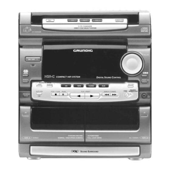
Allgemeiner Teil / General Section M 19-C / M 29-C Bedienhinweise Dieses Kapitel enthält Auszüge aus der Bedienungsanleitung. Weitergehende Informationen entnehmen Sie bitte der gerätespezifischen Bedienungsanleitung, deren Sachnummer Sie in der entsprechenden Ersatzteilliste finden. BEDIENELEMENTE die Abbildung zeigt M29-C ON/OFF –... -
Seite 5: Bedienung Des Systems
M 19-C / M 29-C Allgemeiner Teil / General Section BEDIENUNG DES SYSTEMS Wichtig: Vor der Inbetriebnahme ist sicherzustellen, Sound control daß alle vorbereitenden Maßnahmen durchgeführt Einstellen der Lautstärke wurden. • Den Lautstärkeregler VOLUME nach links oder Das Gerät befindet sich im Bereitschaftsbetrieb,... - Seite 6 Allgemeiner Teil / General Section M 19-C / M 29-C TUNER RDS Search Empfangen eines RDS-Radiosenders Ç RDS bietet Ihnen die Möglichkeit, FM-Sender RDS (Radio Data System) ist ein Rundfunkdienst, mit nach Programmarten auszuwählen. Mehr und dem FM-Sender (UKW) neben dem normalen mehr Sender codieren ihre Programmart und UKW-Rundfunksignal zusätzliche Informationen...
- Seite 7 M 19-C / M 29-C Allgemeiner Teil / General Section CD-WECHSLER Wiedergabe einer CD Warnung! 1 Drücken Sie die Taste B am Gerät oder auf 1 Dieses Gerät ist für herkömmliche CDs konzipiert. Ver- wenden Sie keine Zubehörteile wie Plattenstabilisierungs- der Fernbedienung, um die Wiedergabe zu starten.
-
Seite 8: Einstellen Der Uhrzeit
Allgemeiner Teil / General Section M 19-C / M 29-C CD-WECHSLER Löschen des Programms Programmieren von Stücken (im Stopp-Betrieb) Die auf einer eingelegten CD enthaltenen 1 Drücken Sie die Taste 9 am Gerät oder Stücke können im Stopp-Betrieb des CD- STOP/CLEAR auf der Fernbedienung. -
Seite 9: Weitere Leistungsmerkmale
M 19-C / M 29-C Allgemeiner Teil / General Section EINSTELLEN DES TIMERS WEITERE LEISTUNGSMERKMALE 3a Wenn REC TU gewählt wird, setzen Sie eine Stummschaltung unbespielte Kassette in das Kassettenfach ein. Mit dieser Funktion kann der Ton der Anlage •... -
Seite 10: Remote Control
Allgemeiner Teil / General Section M 19-C / M 29-C CONTROLS REMOTE CONTROL 15 CD/TAPE/TUNER control Remote Control Functions AUTO REV. • First select the source you wish to control by for TAPE – to select the desired play mode. - Seite 11 M 19-C / M 29-C Allgemeiner Teil / General Section TUNER Tuning to radio stations Storing Preset Stations 1 Press TUNER ( BAND ) on the unit or on the You can store up to 20 stations in the FM remote control.
-
Seite 12: Cassette Deck
Allgemeiner Teil / General Section M 19-C / M 29-C CASSETTE DECK Fast Forward/Rewinding Dubbing cassettes (from TAPE DECK A to TAPE DECK B) 1 You can rewind or fast forward the tape by pressing S or T on the set or on the... - Seite 13 M 19-C / M 29-C Allgemeiner Teil / General Section CD CHANGER Selecting a desired track Random function RANDOM Selecting a desired track at the stop mode RANDOM – playing all the tracks in random order 1 Press S or T on the unit or on the disc by disc.
-
Seite 14: Clock Setting
Allgemeiner Teil / General Section M 19-C / M 29-C CLOCK SETTING TIMER SETTING Setting the clock Setting the Timer The clock will display in 24-hour mode, e.g. • The system can switch on to TUNER, CD, 00:00 or 23:59. -
Seite 15: Ausbauhinweise
M 19-C / M 29-C Allgemeiner Teil / General Section Ausbauhinweise Disassembly Instructions 1. Öffnen des Gehäuses 1.Opening the Cabinet - Die jeweils 12 Schrauben in den Gehäuseseitenwänden sowie die - Undo 12 screws on each side of the cover and 6 screws on the rear 6 Schrauben in der Gehäuserückwand herausschrauben und das... - Seite 16 Allgemeiner Teil / General Section M 19-C / M 29-C 5. Cassettenfachklappe ausbauen (Fig. 6) 5. Removing the Cassette Compartment Lid (Fig. 6) - Cassettenfach öffnen, beidseitige Sperrklinke N eindrücken und - Open the cassette compartment, press in the click N on both sides Klappe vorsichtig in Pfeilrichtung abziehen.
- Seite 17 M 19-C / M 29-C Allgemeiner Teil / General Section 7. Endstufe ausbauen 7. Removing the AF Board - CD-Laufwerk ausbauen (Pkt. 2). - Remove the CD drive mechanism (para 2). - 4 Schrauben W (Fig. 8) und 2 Schrauben W (Fig. 9) herausschrau- - Undo 4 screws W (Fig.
- Seite 18 Allgemeiner Teil / General Section M 19-C / M 29-C 11. Schublade ausbauen 11. Dismantling the Tray - Laufwerk ausbauen (Pkt. 2). - Dismantle the drive mechanism (para 2). - Die 4 Schrauben G (Fig. 11) herausschrauben und das Blech H - Undo 4 screws G (Fig.
- Seite 19 M 19-C / M 29-C Allgemeiner Teil / General Section 14. CD-Laufwerk-Einheit ausbauen 14. Removing the CD Drive Mechanism - Schublade herausziehen (siehe Laufwerk ausbauen Pkt. 2). - Pull out the tray (see description for removing the drive mechanism - 4 Schrauben R (Fig. 13) herausschrauben, die Feder T leicht under para 2).
- Seite 20 Allgemeiner Teil / General Section M 19-C / M 29-C 17. Cassettenlaufwerk ausbauen 17. Removing Cassette Drive Mechanism - Frontblende ausbauen (Pkt. 3). - Remove the Front (para 3). - 4 Schrauben b herausschrauben und Laufwerk nach hinten her- - Undo 4 screws b and remove the drive mechanism towards the ausnehmen (Fig.
- Seite 21 M 19-C / M 29-C Allgemeiner Teil / General Section 20. Cassettenlaufwerk-PCB und Steuermagnet ausbauen 20. Removing the Cassette Drive PCB and the Controlling Magnet - Cassettenlaufwerk ausbauen (Pkt. 17). - Remove the cassette drive mechanism (para 17). - Schraube e herausschrauben (Fig. 19).
- Seite 22 Abgleichvorschriften / Adjustment Procedures M 19-C / M 29-C Abgleichvorschriften 1. Tuner Meßgeräte: Meß-/Wobbelsender, Stereocoder, Oszilloskop, Klirrfaktormeßgerät, DC-Voltmeter, NF-Voltmeter Servicearbeiten nach Austausch des Frontends: Abgleich Nr. 2 Das Frontend ist ein komplett abgeglichener Baustein. Nur das ZF-Filter muß dem ZF-Verstärker angeglichen werden.
- Seite 23 M 19-C / M 29-C Abgleichvorschriften / Adjustment Procedures 2. Cassettenteil Meßgeräte/Meßmittel: NF-Voltmeter, Frequenzzähler, Cr-Testkassette 448A Materialnummer: 35079 023 0000 Abgleich Vorbereitung Abgleichvorgang 1. Azimut Die Einstellschrauben der Tonköpfe sind durch kleine Mit den entsprechenden Schrauben linken und rechten Aussparungen in der Frontblende zugänglich.
-
Seite 24: Adjustment Procedures
Abgleichvorschriften / Adjustment Procedures M 19-C / M 29-C Adjustment Procedures 1. Tuner Measuring instruments: Standard/sweep signal generator, stereo coder, oscilloscope, distortion meter, DC voltmeter, AF voltmeter Service works after replacing the front end: Alignment no. 2 The frontend is a completely adjusted module. Only the IF filter is to be tuned to the IF amplifier. - Seite 25 M 19-C / M 29-C Abgleichvorschriften / Adjustment Procedures 2. Tape Deck Measuring instruments/Test equipment: AF voltmeter, frequency counter, Cr test cassette 448A Part No.: 35079 023 0000 Alignment Preparation Procedure 1. Azimuth Access to the adjustment screws of the audio heads is Set the left and right channel with the respective screws for possible through small cutouts on the front panel.
-
Seite 27: Mains Unit Board
M 19-C / M 29-C Platinenabbildungen und Schaltpläne / Layout of PCBs and Circuit Diagrams M 19-C / M 29-C Platinenabbildungen und Schaltpläne / Layout of PCBs and Circuit Diagrams Verdrahtungsplan / Wiring Diagram TRAFO HAUPTPLATTE MAIN BOARD VERSTÄRKERPLATTE AMPLIFIER BOARD... - Seite 28 Platinenabbildungen und Schaltpläne / Layout of PCBs and Circuit Diagrams M 19-C / M 29-C Platinenabbildungen und Schaltpläne / Layout of PCBs and Circuit Diagrams M 19-C / M 29-C Schaltplan – Netzteilplatte / Circuit Diagram – Mains Unit Board...
-
Seite 29: Display
M 19-C / M 29-C Platinenabbildungen und Schaltpläne / Layout of PCBs and Circuit Diagrams M 19-C / M 29-C Platinenabbildungen und Schaltpläne / Layout of PCBs and Circuit Diagrams Platinenabbildung / Layout of PCB: Für die tatsächliche Bauteilbestückung ist das Schaltbild maßgebend! Ansicht von der Bestückungsseite / View of component side... - Seite 30 Platinenabbildungen und Schaltpläne / Layout of PCBs and Circuit Diagrams M 19-C / M 29-C Platinenabbildungen und Schaltpläne / Layout of PCBs and Circuit Diagrams M 19-C / M 29-C Platinenabbildungen / Layout of PCBs: VON VORNE VON UNTEN VON UNTEN Ansicht von der Bestückungsseite / View of component side...
- Seite 31 Platinenabbildungen und Schaltpläne / Layout of PCBs and Circuit Diagrams M 19-C / M 29-C Platinenabbildungen und Schaltpläne / Layout of PCBs and Circuit Diagrams Schaltplan – CD-Tastenplatte, Steuerplatte M 19-C / Circuit Diagram – CD Key Board, Control Board M 19-C + 5 V R505...
- Seite 32 Platinenabbildungen und Schaltpläne / Layout of PCBs and Circuit Diagrams M 19-C / M 29-C Platinenabbildungen und Schaltpläne / Layout of PCBs and Circuit Diagrams M 19-C / M 29-C Schaltplan – CD-Tastenplatte, Steuerplatte M 29-C / Circuit Diagram – CD Key Board, Control Board M 29-C R590 1.8K...
- Seite 33 Platinenabbildungen und Schaltpläne / Layout of PCBs and Circuit Diagrams M 19-C / M 29-C Platinenabbildungen und Schaltpläne / Layout of PCBs and Circuit Diagrams Schaltplan – Kopfhörerplatte, Hauptplatte M 19-C / Circuit Diagram – Headphone Board, Main Board M 19-C TO TUNER PART PAGE 3 - 20 NF rechts "Aufnahme"...
- Seite 34 Platinenabbildungen und Schaltpläne / Layout of PCBs and Circuit Diagrams M 19-C / M 29-C Platinenabbildungen und Schaltpläne / Layout of PCBs and Circuit Diagrams M 19-C / M 29-C Schaltplan – Kopfhörerplatte, Hauptplatte M 29-C / Circuit Diagram – Headphone Board, Main Board M 29-C...
- Seite 35 M 19-C / M 29-C Platinenabbildungen und Schaltpläne / Layout of PCBs and Circuit Diagrams M 19-C / M 29-C Platinenabbildungen und Schaltpläne / Layout of PCBs and Circuit Diagrams Platinenabbildungen / Layout of PCBs: VON VORNE VON UNTEN VON UNTEN...
- Seite 36 Platinenabbildungen und Schaltpläne / Layout of PCBs and Circuit Diagrams M 19-C / M 29-C Platinenabbildungen und Schaltpläne / Layout of PCBs and Circuit Diagrams M 19-C / M 29-C Schaltplan – Tuner-Teil M 19-C / Circuit Diagram – Tuner Part M 19-C BU1923F TCTR SCOUT...
- Seite 37 M 19-C / M 29-C Platinenabbildungen und Schaltpläne / Layout of PCBs and Circuit Diagrams M 19-C / M 29-C Platinenabbildungen und Schaltpläne / Layout of PCBs and Circuit Diagrams Schaltplan – Tuner-Teil M 29-C / Circuit Diagram – Tuner Part M 29-C...
-
Seite 38: Ic Block Diagrams
Platinenabbildungen und Schaltpläne / Layout of PCBs and Circuit Diagrams M 19-C / M 29-C Platinenabbildungen und Schaltpläne / Layout of PCBs and Circuit Diagrams M 19-C / M 29-C Schaltplan – Verstärkerplatte M 19-C / Circuit Diagram – Amplifier Board M 19-C R216 100(FUSIBLE 1/4W) IC203... - Seite 39 M 19-C / M 29-C Platinenabbildungen und Schaltpläne / Layout of PCBs and Circuit Diagrams M 19-C / M 29-C Platinenabbildungen und Schaltpläne / Layout of PCBs and Circuit Diagrams Schaltplan – Verstärkerplatte M 29-C / Circuit Diagram – Amplifier Board M 29-C...
- Seite 40 Platinenabbildungen und Schaltpläne / Layout of PCBs and Circuit Diagrams M 19-C / M 29-C Platinenabbildungen und Schaltpläne / Layout of PCBs and Circuit Diagrams M 19-C / M 29-C Platinenabbildungen / Layout of PCBs: Ansicht von der Bestückungsseite / View of component side Für die tatsächliche Bauteilbestückung ist das Schaltbild maßgebend!
- Seite 41 M 19-C / M 29-C Platinenabbildungen und Schaltpläne / Layout of PCBs and Circuit Diagrams M 19-C / M 29-C Platinenabbildungen und Schaltpläne / Layout of PCBs and Circuit Diagrams Schaltplan – Cassetten-Platte / Circuit Diagram – Cassette Board NF rechts "Aufnahme" Cass.
- Seite 42 Platinenabbildungen und Schaltpläne / Layout of PCBs and Circuit Diagrams M 19-C / M 29-C Platinenabbildungen und Schaltpläne / Layout of PCBs and Circuit Diagrams M 19-C / M 29-C Platinenabbildungen / Layout of PCBs: Ansicht von der Bestückungsseite / View of component side...
- Seite 43 M 19-C / M 29-C Platinenabbildungen und Schaltpläne / Layout of PCBs and Circuit Diagrams M 19-C / M 29-C Platinenabbildungen und Schaltpläne / Layout of PCBs and Circuit Diagrams Schaltplan – CD-Platte / Circuit Diagram – CD Board V-CEN...
- Seite 44 Platinenabbildungen und Schaltpläne / Layout of PCBs and Circuit Diagrams M 19-C / M 29-C Platinenabbildungen und Schaltpläne / Layout of PCBs and Circuit Diagrams M 19-C / M 29-C IC-Block-Diagramme / IC Block Diagrams IC700 LA9241M IC702 LA6537 U601 TA8189...
- Seite 45 M 19-C / M 29-C Platinenabbildungen und Schaltpläne / Layout of PCBs and Circuit Diagrams IC202 STK4152 (M 19-C), STK4192 (M 29-C) IC303 BU1923F GRUNDIG Service 3 - 38...
- Seite 46 Platinenabbildungen und Schaltpläne / Layout of PCBs and Circuit Diagrams M 19-C / M 29-C IC302 LC72131 REVERENCE PHASE DETECTOR DIVIDER CHARGE PUMP XOUT UNLOCK SWALLOW COUNTER FM IN DETECTOR 1/16, 1/17 4bits A IN A OUT 12 bits PROGRAMMABLE...
- Seite 47 M 19-C / M 29-C Platinenabbildungen und Schaltpläne / Layout of PCBs and Circuit Diagrams IC308 LC75396E IC304 TDA2822M IC502 24C02 GRUNDIG Service 3 - 40...
- Seite 48 Platinenabbildungen und Schaltpläne / Layout of PCBs and Circuit Diagrams M 19-C / M 29-C IC504 BA3835S IC501, IC503, IC506 14094 BLOCK DIAGRAM Latch 1 3-State Buffer 1 Register Stage 1 V DD Clock Clock Strobe Serial Clock Clock Strobe...
-
Seite 49: Spare Parts Lists And Exploded Views
M 19-C / M 29-C Ersatzteillisten und Explosionszeichnungen / Spare Parts Lists and Exploded Views Ersatzteillisten und Explosionszeichnungen / Spare Parts Lists and Exploded Views Explosionszeichnung – M 19-C / Exploded View – M 19-C GRUNDIG Service 4 - 1... - Seite 50 Ersatzteillisten und Explosionszeichnungen / Spare Parts Lists and Exploded Views M 19-C / M 29-C Ersatzteillisten und Explosionszeichnungen / Spare Parts Lists and Exploded Views M 19-C / M 29-C Explosionszeichnung – M 29-C / Exploded View – M 29-C...
- Seite 51 Explosionszeichnung – Cassettenlaufwerke CRH4427, CRH4428 Exploded View – Cassette Drive Mechanism CRH4427, CRH4428...
-
Seite 52: Ersatzteilliste Spare Parts List
TUER BATTERIE FERNBEDIENUNG BATTERY LID REMOTE CONTROL © POS. NO. FIG. PART NUMBER QTY. 0110.000 75955 002 9100 FERNBEDIENUNG M 19-C/M 29-C REMOTE CONTROL M 19-C/M 29-C 0120.000 75955 006 2800 75403 710 5100 M 19-C M 19-C 72010 758 3000 BEDIENUNGSANLEITUNG INSTRUCTION MANUAL 0001.000... - Seite 53 POS. NR. SACHNUMMER BEZEICHNUNG POS. NR. SACHNUMMER BEZEICHNUNG POS. NR. SACHNUMMER BEZEICHNUNG POS. NR. SACHNUMMER BEZEICHNUNG POS. NO. PART NUMBER DESCRIPTION POS. NO. PART NUMBER DESCRIPTION POS. NO. PART NUMBER DESCRIPTION POS. NO. PART NUMBER DESCRIPTION VR 00302 75955 002 6500 ESTR S6 2KOHM SW 00505 75954 036 7700 TAKTSCHALTER 1P2T 4,3MM Q 00627...
- Seite 54 Q/S LED LIGTH GUIDE 0109.000 75955 002 7200 TUER BATTERIE FERNBEDIENUG BATTERY LID REMOTE CONTROL 0110.000 75955 002 9100 FERNBEDIENUNG M 19-C/M 29-C REMOTE CONTROL M 19-C/M 29-C 75403 810 5100 M 29-C M 29-C 0120.000 75955 006 2900 0001.000 75955 002 0100...
- Seite 55 POS. NR. SACHNUMMER BEZEICHNUNG POS. NR. SACHNUMMER BEZEICHNUNG POS. NR. SACHNUMMER BEZEICHNUNG POS. NR. SACHNUMMER BEZEICHNUNG POS. NO. PART NUMBER DESCRIPTION POS. NO. PART NUMBER DESCRIPTION POS. NO. PART NUMBER DESCRIPTION POS. NO. PART NUMBER DESCRIPTION SP 00300 75955 002 9200 TERMINAL LS L 00502 75955 002 7600 INDUCTOR CEC36-101K Q 00614...
- Seite 56 Explosionszeichnung – CD-Wechsler ORPB330 Exploded View – CD Changer ORPB330 Ersatzteilliste HIFI / AUDIO Spare Parts List 12 / 98 LAUFWERK 3 CD ORPB 330 MATERIAL-NR. / PART NO.: 75955 002 5400 POS. NR. ABB. MATERIAL-NR. ANZ. BEZEICHNUNG DESCRIPTION © POS.