Grundig M 28-C Servicehandbuch
Inhaltsverzeichnis
Service Manual
Grundig Service
Hotline Deutschland...
...Mo.-Fr. 8.00-16.30 Uhr
Technik:
TV/SAT
0180/52318-41
VCR/LiveCam
0180/52318-42
HiFi/Audio
0180/52318-43
Car Audio
0180/52318-44
Telekommunikation
0180/52318-45
Fax:
0180/52318-51
Ersatzteil-Bestellannahme:
0180/52318-40
Telefon:
0180/52318-50
Fax:
Zusätzlich erforderliche
Unterlagen für den Komplettservice
Additionally required
Service Manuals for the Complete Service
Service
Service
Manual
Manual
M 18-C
M 28-C
Sicherheit
Safety
M 38-C
M 48-DC
Sach-Nr./Part No.
Sach-Nr./Part No.
72010-755.85
72010-800.00
3
1
2
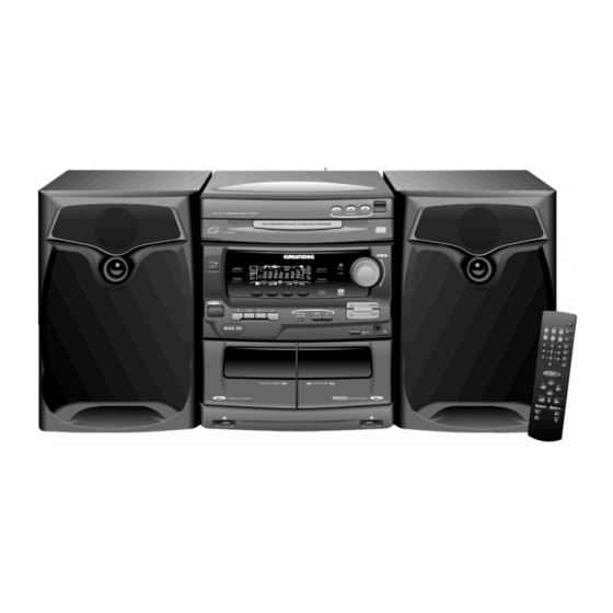
HiFi A/V SURROUND MINI SYSTEM
DISC SELECT
HIGH PERFORMANCE DIGITAL TO ANALOGUE CONVERSION
2
3
1
CD CHANGER
TIMER
CD TAPE
1
FRONT
D PRO LOGIC
D 3 STEREO
PLAY
CD
STEREO
BACK
PHANTOM
PROG
MODE
2
NORMAL
RECORD
DBB
PROGRAM
3
D NR
SHUFFLE
TIMER SET
SW
LW
FMMW
HSD
REC
AMPM
TIMER
SET CLOCK
DEMO
DUBBING
SIDE
BAND
RDS
SHUFFLE
MODE
TIMER
CLEAR
PRESET
TUNING
INFRARED
SENSOR
R D S
ON/OFF
ON
DOLBY PRO LOGIC
CD
TUNER
TAPE 1/2
AUX
INCREDIBLE
DBB
DSC
OFF
SURROUND
M48 -DC
B NR
SYNCHRO DUBBING
AUTOREVERSE
TAPE 1
PLAYBACK/LOGIC DRIVE
DOLBY B NR
RECORD/PLAYBACK
OPEN/CLOSE
VOLUME
PHANTOM
3-STEREO
TAPE 2
HiFi
M 18-C
M 28-C
M 38-C
M 48-DC
Btx * 32700 #
Sachnummer
Part Number 72010-755.85
Änderungen vorbehalten
Subject to alteration
Printed in Germany
VK233 1197
Inhaltsverzeichnis

Verwandte Anleitungen für Grundig M 28-C


Inhaltszusammenfassung für Grundig M 28-C
- Seite 1 Service Manual HiFi M 18-C Grundig Service M 28-C Hotline Deutschland... M 38-C ...Mo.-Fr. 8.00-16.30 Uhr Technik: M 48-DC TV/SAT 0180/52318-41 VCR/LiveCam 0180/52318-42 HiFi/Audio 0180/52318-43 Car Audio 0180/52318-44 Telekommunikation 0180/52318-45 Fax: 0180/52318-51 Ersatzteil-Bestellannahme: 0180/52318-40 Telefon: 0180/52318-50 Fax: HiFi A/V SURROUND MINI SYSTEM...
- Seite 2 CD Changer CDC 3 MG ............4 - 39 NF-Teil M 18-C, M 28-C, M 38-C ........4 - 45 AF Part M 18-C, M 28-C, M 38-C ........4 - 45 NF-Teil M 48-DC ..............4 - 49 AF Part M 48-DC ..............4 - 49 DPL-Platte (nur M 48-DC) ...........
-
Seite 3: Allgemeiner Teil
Signal-to-noise ratio ............≥ 75dB Eingangsempfindlichkeit Aux ..........400mV Input sensitivity Aux ............400mV Lautsprecher M 18-C, M 28-C, M 38-C ........3Ω Speakers M 18-C, M 28-C, M 38-C .......... 3Ω Lautsprecher M 48-DC ............≥ 6Ω Speakers M 48-DC ..............≥ 6Ω... -
Seite 4: Ausbauhinweise
- Cassettenfach öffnen und Klappe vorsichtig in Pfeilrichtung abzie- - Open the cassette lid and carefully pull off the cover in the direction hen. of the arrow. Fig. 1 Fig. 2 Fig. 3 Fig. 4 Fig. 5 1 - 4 GRUNDIG Service... - Seite 5 - When mounting the Board take care that it fits in the guides - Beim Wiedereinsetzen der Leiterplatte darauf achten, daß sie richtig (Fig. 11). in den Führungen (Fig. 11) sitzt. Fig. 7 Fig. 6 Fig. 9 Fig. 8 Fig. 10 Fig. 11 GRUNDIG Service 1 - 5...
- Seite 6 - Remove Power Amplifier together with its heat sink and cover. Open Steckverbinder nach Bedarf öffnen. connectors if necessary. 10. Ausbau der Netzteilplatte (M 28-C) 10. Removing the Power Supply Board (M 28-C) - Endstufe ausbauen (Pkt. 9). - Remove Power Amplifier (para 9). - Die 2 Schrauben (Fig.
- Seite 7 - Remove the Power Supply / AF Amplifier Module (para 13). - Schraube (Fig. 21) und 2 Schrauben (Fig. 22) herausschrau- - Undo srew (Fig. 21) and 2 screws (Fig. 22). ben. Fig. 18 Fig. 17 Fig. 19 Fig. 20 Fig. 21 Fig. 22 GRUNDIG Service 1 - 7...
- Seite 8 - Remove the Power Supply / AF Amplifier Module (para 13). - Verbindungsplatte abziehen (Fig. 23). - Pull off the connection Board (Fig. 23). - 2 Schrauben herausschrauben (Fig. 25). - Undo 2 screw (Fig. 25). Fig. 23 Fig. 24 Fig. 25 1 - 8 GRUNDIG Service...
- Seite 9 - When reassembling take care that the PCBs fit into their guides Führungen (Fig. 30 und 31) achten. (Fig. 30 and 31). Fig. 26 Fig. 27 Fig. 28 Fig. 29 ¡ & Fig. 30 Fig. 31 ¡ GRUNDIG Service 1 - 9...
- Seite 10 - Beim Wiedereinbau der Leiterplatte auf die 3 Schalter (Fig. 34) - When mounting the PCB look for the 3 switches (Fig. 34). achten! Fig. 32 Fig. 33 Fig. 34 Öffnen eines Flexprint-Steckers Opening a flexprint connector 1 - 10 GRUNDIG Service...
- Seite 11 - Undo screw (Fig. 37) and remove turntable. - 6 Schrauben (Fig. 38) herausschrauben und Antriebsmechanik - Undo 6 screws (Fig. 38) and remove drive mechanism. herausnehmen. Fig. 35 Fig. 36 Fig. 37 Fig. 38 GRUNDIG Service 1 - 11...
- Seite 12 Stellung bringen, so daß keine Zähne sichtbar sind (Fig. 42)! Die the eccentric wheel like in Fig. 43. Exzenterscheibe dann wie in Fig. 43 aufsetzen. Fig. 39 Fig. 40 Fig. 41 Fig. 42 Fig. 43 1 - 12 GRUNDIG Service...
- Seite 13 Einfetten grease die Nut einfetten grease inside groove auf der Oberseite einfetten grease on top of rib einfetten grease einfetten grease Oberfläche der 4 Rechtecke einfetten die Schieber einfetten grease on 4 rectangular surfaces grease on slide die 4 Nuten einfetten die Nuten einfetten grease on 4 profile groves einfetten...
- Seite 14 29. Removing a Pressure Roller Lever (Fig. 47 / 48) - Die Cassettenlaufwerke ausbauen (Pkt. 27). - Remove the drive mechanisms (para 27). - Disengage the locking lug carefully and pull out the pressure - Rastnase vorsichtig ausrasten und den Andruckrollenhebel abziehen. roller lever 1 - 14 GRUNDIG Service...
- Seite 15 - 2 Schrauben herausdrehen und Plattenhalter abnehmen - Remove the drive belt from the flywheel and motor pulley (Fig. 52). (Fig. 50). - Riemen von den Schwungscheiben und der Motorriemenschei- (Fig. 50) abnehmen. Fig. 53 GRUNDIG Service 1 - 15...
-
Seite 16: Service Test Program
Press the button A2. The display shows "NEW" for 2 seconds before the Taste A2 drücken. Im Display wird für 2 Sekunden "NEW" angezeigt, home position of the service test program is reached. danach wird in die Service-Test-Programm-Grundstellung zurückge- kehrt. 1 - 16 GRUNDIG Service... - Seite 17 Press button "DBB" again: "NOM" is shown in the display for 2 seconds. Normale Uhrgeschwindigkeit wird eingestellt. The normal watch speed is set. Beenden Sie den Test immer in Stellung NOM! End this test always when NOM is set! GRUNDIG Service 1 - 17...
- Seite 18 Karussell blockiert zwischen 2 Disks E 1075 Drawer blocked in the middle E 1075 Schublade blockiert beim Öffnen oder Schließen E 1076 Drawer blocked in open or closed state E 1076 Schublade blockiert in offenem oder geschlosse- nem Zustand 1 - 18 GRUNDIG Service...
- Seite 19 BEDIENELEMENTE M 48-DC BEDIENELEMENTE M 18-C, M 28-C, M 38-C ON/OFF – Zum Einschalten des Gerätes und zum ON/OFF – Zum Einschalten des Gerätes und zum Umschalten auf Bereitschaftsbetrieb. Umschalten auf Bereitschaftsbetrieb. SOURCE SELECTION – Zum Wählen von: SOURCE SELECTION – Zum Wählen von: TUNER : Radiobetrieb.
-
Seite 20: Bedienung Des Systems M 18-C, M 28-C, M 38-C
BEDIENUNG DES SYSTEMS M 18-C, M 28-C, M 38-C BEDIENUNG DES SYSTEMS M 48-DC Sound control Klangkontrolle VOLUME Einstellen der Lautstärke Einstellen der Lautstärke VOLUME TIMER • Den Lautstärkeregler VOLUME nach links oder • Drehen Sie den Lautstärkeregler VOLUME nach... -
Seite 21: Bandaufnahmen
TUNER TUNER Abstimmen auf Vorwahlsender Speichern von Vorwahlsendern Wenn das Gerät auf einen RDS-Sender abgestimmt • Drücken Sie die Taste PRESET 4 oder 3 (oder Ç ist, werden das RDS-Logo ( ) und der Sendername Es können bis zu 20 Sender gespeichert werden. Wenn VOLUME PREV ¡... -
Seite 22: Einstellen Der Uhrzeit
CD-WECHSLER CD-WECHSLER Wiedergabe einer Platte Suchen nach einer bestimmten Warnung! Passage während der Wiedergabe 1 Drücken Sie die Taste B (oder PLAY 2 auf der 1 Dieses Gerät ist für herkömmliche CDs HiFi A/V SURROUND MINI SYSTEM FRONT DISC SELECT OPEN/CLOSE Fernbedienung), um die Wiedergabe zu starten. - Seite 23 – to open TAPE 1 cassette compartment. – to open TAPE 1 cassette compartment. 19 TAPE DECK 1 19 TAPE DECK 1 REMOTE CONTROL M 18-C, M 28-C, M 38-C REMOTE CONTROL M 48-DC Inserting the batteries into the Inserting the batteries into the –...
- Seite 24 OPERATING THE SYSTEM M 18-C, M 28-C, M 38-C OPERATING THE SYSTEM M 48-DC Sound control Sound control VOLUME Volume Adjustment VOLUME Volume Adjustment TIMER • Rotate VOLUME right or left (or press • Rotate VOLUME right or left (or press VOLUME +...
-
Seite 25: Cassette Deck
TUNER TUNER Storing Preset Stations Tuning to Preset Stations When you have tuned to an RDS station, the RDS Ç logo ( ) and the station name will appear on the • Press PRESET 4 or 3 (or PREV ¡ or NEXT ™ on You can store up to 20 stations in the memory. -
Seite 26: Clock Setting
CD CHANGER CD CHANGER Playing a Disc Searching for a particular passage Warning! during playback 1 Press B (or PLAY 2 on the remote control) to 1 This set is designed for conventional CDs. Do HiFi A/V SURROUND MINI SYSTEM FRONT DISC SELECT OPEN/CLOSE... -
Seite 27: Power Supply
(pin 13-15/13-11). – (nur M 48-DC:) 2 Dioden des Brücken-Gleichrichters 6201, mit See Fig. 2 and 3 for M 28-C resp. Fig. 6 and 7 for M 48-DC. 6202/6203 (für +B2), unter Verwendung von ca. 70% der Sekun- •... - Seite 28 • Via the AMP_ON control line, connected to pins 6 (Stby), the power amplifiers are switched on/off by the µP. ausgeschaltet. High-Pegel (ca. 4,5V): Leistungsverstärker eingeschaltet High level (approx. 4,5V): power amplifiers switched on Low-Pegel (ca. 0V): Leistungsverstärker ausgeschaltet Low level (approx. 0V): power amplifiers switched off 2 - 2 GRUNDIG Service...
- Seite 29 ⇒ +A (+36V) for high output power ⇒ +A (+36V) für hohe Ausgangsleistung Principle / benefit of Super Class G (Fig. 4 for M 28-C resp. Fig. 8 Leistungsmerkmale / Vorteile des Super Class G (Fig. 4 für M 28-C for M 48-DC) bzw.
-
Seite 30: Schaltungsbeschreibung / Circuit Desription
Schaltungsbeschreibung / Circuit Desription M 18-C … M 48-DC 1205 M 28-C 1008 4,5V 10,5V 6204 1203 1N5392 6,5V 6205 6,5V 1204 1N5392 10,5V 2206 100n Signal path D5SBA20 pos. halfwave 6201 100n 6201 neg. halfwave D5SBA20 2211 Fig. 1... - Seite 31 Output power Output power Output power Power dissipation Power Power dissipation dissipation Voltage drop on power stage IC Voltage drop on switching transistor(s) Benefit - voltage drop on switching transistor(s) reduces total power dissipation Fig. 8 GRUNDIG Service 2 - 5...
- Seite 32 5123 ten Sie darauf, daß nur Filter mit gleicher Kennfarbe bestückt sind. 9101 ZF (MHz) ZF-Filter ZF-Filter Kennbuchstabe Farbe 5114 5111 10,6500 schwarz 10,6750 blau 5112 2106 10,7000 5102 1103 10,7250 orange 5103 10,7500 weiß 3 - 1 GRUNDIG Service...
- Seite 33 (R) bzw. Pin 3 und Mit 3655 (R) bzw. 3656 (L) auf 5mV 0,5dB einstellen (L) von 1711 1701 3785 3773 1711 2696 2695 5632 5631 etf2-p2-951114-1 3139 113 33192 1742 1741 1706 3682 3684 1704 GRUNDIG Service 3 - 2...
-
Seite 34: Adjustment Procedures
9101 IF (MHz) IF Filter IF Filter Ident letter Colour 5114 5111 10.6500 black 10.6750 blue 5112 2106 10.7000 5102 1103 10.7250 orange 5103 10.7500 white 3 - 3 GRUNDIG Service... - Seite 35 (R) resp. Pin 3 and With 3655 (R) resp. 3656 (L) set 5mV 0.5dB (L) of 1711 1701 3785 3773 1711 2696 2695 5632 5631 etf2-p2-951114-1 3139 113 33192 1742 1741 1706 3682 3684 1704 GRUNDIG Service 3 - 4...
- Seite 36 Abgleichvorschriften / Adjustment Procedures M 18-C … M 48-DC Notizen / Notes 3 - 5 GRUNDIG Service...
- Seite 37 Schaltpläne und Druckplattenabbildungen / Circuit Diagrams and Layout of PCBs Schaltpläne und Druckplattenabbildungen / Circuit Diagrams and Layout of PCBs Blockschaltplan M 28-C, M 48-DC / Block Diagram M 28-C, M 48-DC Blockschaltplan M 18-C, M 38-C / Block Diagram M 18-C, M 38-C...
- Seite 38 Schaltpläne und Druckplattenabbildungen / Circuit Diagrams and Layout of PCBs M 18-C … M 48-DC Verdrahtungsplan M 18-C / Wiring Diagram M 18-C Verdrahtungsplan M 28-C, M 48-DC / Wiring Diagram M 28-C, M 48-DC 4 - 3 GRUNDIG Service...
- Seite 39 Schaltpläne und Druckplattenabbildungen / Circuit Diagrams and Layout of PCBs M 18-C … M 48-DC Schaltpläne und Druckplattenabbildungen / Circuit Diagrams and Layout of PCBs Verdrahtungsplan M 38-C / Wiring Diagram M 38-C Display M 18-C, M 28-C, M 38-C Display M 48-DC GRUNDIG Service 4 - 5...
- Seite 40 FM GND RF GND IF GND Dig. GND RF GND FM-Demod AF-Out Indc. MPX-In AM-RF AM-OSC 10,7MHz 75kHz 3142 5102 5123 2106 5103 5122 VCC1 ANTI BIRDY FILTER VCC2 MW/LW-SELECTION 4 - 7 GRUNDIG Service 4 - 8 GRUNDIG Service...
- Seite 41 FM mode stereo Signal path 5123 6105 ..V 6105 6107 K 20 ..V 6120 E 18 7101 C 16 7103 K 17 7104 7105 7109 L 10 9533 7110 7122 7124 GRUNDIG Service 4 - 9 GRUNDIG Service 4 - 10...
- Seite 42 The circuit diagram is relevant for the actual component assembly! Bestückungsseite / Component Side Lötseite / Solder Side 9108 3161 3160 3159 3158 9118 9102 9120 9121 9123 3167 9124 9126 9125 2129 9115 2128 3125 9114 9100 4 - 11 GRUNDIG Service 4 - 12 GRUNDIG Service...
- Seite 43 Schaltpläne und Druckplattenabbildungen / Circuit Diagrams and Layout of PCBs M 18-C … M 48-DC Schaltpläne und Druckplattenabbildungen / Circuit Diagrams and Layout of PCBs Schaltplan Front M 18-C, M 28-C, M 38-C / Circuit Diagram Front M 18-C, M 28-C, M 38-C Bauteile X 3466...
- Seite 44 Schaltpläne und Druckplattenabbildungen / Circuit Diagrams and Layout of PCBs M 18-C … M 48-DC Druckplatte Front M 18-C, M 28-C, M 38-C / Front PCB M 18-C, M 28-C, M 38-C Bestückungsseite / Component Side Für die tatsächliche Bauteilbestückung ist das Schaltbild maßgebend!
- Seite 45 M 18-C … M 48-DC Schaltpläne und Druckplattenabbildungen / Circuit Diagrams and Layout of PCBs Druckplatte Front M 18-C, M 28-C, M 38-C / Front PCB M 18-C, M 28-C, M 38-C Lötseite / Solder Side Für die tatsächliche Bauteilbestückung ist das Schaltbild maßgebend!
- Seite 46 G 15 7416 3455 G 15 7417 3456 7420 3457 7421 3458 7428 3459 9400 M 18 3460 9440 3461 9538 3462 9559 3463 3465 G 14 3466 G 13 4 - 19 GRUNDIG Service 4 - 20 GRUNDIG Service...
- Seite 47 9449 9465 9481 9497 1415 1431 2426 3452 5407 6425 7428 9416 9433 9450 9466 9482 9498 1416 1432 2438 3453 5410 6445 9400 9417 9435 9451 9467 9483 9538 GRUNDIG Service 4 - 21 GRUNDIG Service 4 - 22...
- Seite 48 3559 4422 4488 7406 2417 2458 3415 3431 3459 3477 3498 3519 3542 3571 4424 4500 7407 2418 2460 3416 3432 3460 3478 3499 3520 3543 3572 4425 4533 7414 4 - 23 GRUNDIG Service 4 - 24 GRUNDIG Service...
- Seite 49 7653 1707 3680 PHOTO 7654 7655 7657 3679 CRO2 7658 7650 7659 7660 BC848C 7661 HALF 7662 7663 7664 7665 7666 9783 EOT(B) 3630 SOLB/MOTB 3609 3759 EOT(A) SOLA/MOTA NS/HS GRUNDIG Service 4 - 25 GRUNDIG Service 4 - 26...
- Seite 50 3691 7780 (1702) BC848C 3692 page 4-14 3693 page 4-20 3694 G 18 3695 3701 3702 3703 3704 3705 3706 3707 3708 3709 3710 3711 3712 3713 3714 3715 3716 4 - 27 GRUNDIG Service 4 - 28 GRUNDIG Service...
- Seite 51 2637 2741 3656 5701 9605 9720 9791 2638 2761 3658 5702 9606 9721 9792 2641 2762 3660 5703 9698 9722 9793 2642 2763 3682 6651 9699 9723 9797 2643 2765 3684 6652 9700 9724 9799 GRUNDIG Service 4 - 29...
-
Seite 52: Schaltpläne Und Druckplattenabbildungen / Circuit Diagrams And Layout Of Pcbs
2708 2735 3616 3644 3685 3716 7781 7783 2709 2737 3618 3645 3686 3717 7784 2710 2738 3619 3646 3687 3718 2711 2740 3620 3647 3688 3719 7787 7788 2717 2752 3621 3648 3689 3720 4 - 30 GRUNDIG Service... - Seite 53 SHR_CL page 4-20 OPEN/CLOSE SWITCH SHIFT 1882 REGISTER HEF4094BT CARROUSEL SWITCH SWITCH INFO SWITCH INFO SWITCH INFO 7871 TDA7073A CARROUSEL MOTOR To 53 AF page 4-45 TRAY MOTOR page 4-49 GRUNDIG Service 4 - 31 GRUNDIG Service 4 - 32...
- Seite 54 GNDA 7808 2818 Servo-decoder: x800 -> x850 3819 BC548 ALPC 47u/10V 100n 2848 Audio-part x851 -> x870 47u/10V 2830 GNDA 1800 LDON Interface + Loader x871 -> x899 100n GNDA 4 - 33 GRUNDIG Service 4 - 34 GRUNDIG Service...
- Seite 55 3829 3830 M 11 3832 3833 M 12 Für die tatsächliche Bauteilbestückung ist das Schaltbild maßgebend! 3834 3835 The circuit diagram is relevant for the actual component assembly! 3836 3837 GRUNDIG Service 4 - 35 GRUNDIG Service 4 - 36...
- Seite 56 7871 1874 TDA7073A To 23 Front +10V CARROUSEL page 4-14 MOTOR SWITCH INFO page 4-20 To 53 AF page 4-45 TRAY MOTOR page 4-49 To 1805 CDC page 4-42 1873 4 - 37 GRUNDIG Service 4 - 38 GRUNDIG Service...
- Seite 57 2837 2856 B 13 3806 3823 3842 3862 G 10 7801A MP816 MP838 MP851 2806 2821 2838 2859 B 11 3807 3824 3863 G 13 7801B MP817 MP839 MP852 3843 GRUNDIG Service 4 - 39 GRUNDIG Service 4 - 40...
- Seite 58 MP867 3896 G 10 1882 2862 A 11 2877 G 11 3855 3871 E 11 3881 3898 D 12 7873 D 10 MP801 E 12 MP810 G 13 MP835 MP868 4 - 41 GRUNDIG Service 4 - 42 GRUNDIG Service...
- Seite 59 Für die tatsächliche Bauteilbestückung ist das Schaltbild maßgebend! Für die tatsächliche Bauteilbestückung ist das Schaltbild maßgebend! The circuit diagram is relevant for the actual component assembly! The circuit diagram is relevant for the actual component assembly! GRUNDIG Service 4 - 43 GRUNDIG Service 4 - 44...
- Seite 60 M 18-C … M 48-DC Schaltpläne und Druckplattenabbildungen / Circuit Diagrams and Layout of PCBs M 18-C … M 48-DC Schaltplan NF-Teil M 18-C, M 28-C, M 38-C / Circuit Diagram AF Part M 18-C, M 28-C, M 38-C 3540 3541...
- Seite 61 Schaltpläne und Druckplattenabbildungen / Circuit Diagrams and Layout of PCBs Druckplatte NF-Teil M 18-C, M 28-C, M 38-C / PCB AF Part M 18-C, M 28-C, M 38-C Druckplatte NF-Teil M 18-C, M 28-C, M 38-C / PCB AF Part M 18-C, M 28-C, M 38-C Bestückungsseite / Component Side...
- Seite 62 3520 3538 3556 3574 G 11 2504 2524 2543 2573 2596 2619 3503 3521 3539 3557 3575 2505 2525 2544 2574 2597 2620 3504 3522 3540 G 14 3558 3576 4 - 49 GRUNDIG Service 4 - 50 GRUNDIG Service...
- Seite 63 3556 3595 3652 4510 1518 2548 2583 3589 9518 9573 2619 3522 3557 3596 3654 4511 1520 2551 2584 3601 9519 9578 2621 3524 3558 3597 3655 4512 1521 2552 GRUNDIG Service 4 - 51 GRUNDIG Service 4 - 52...
- Seite 64 2567 2580 O 26 3502 3515 3546 3564 M 21 3612 3645 6556 7555 2518 2531 2548 2568 M 21 2585 3503 3516 3547 3565 3613 3646 6557 7561 2505 4 - 53 GRUNDIG Service 4 - 54 GRUNDIG Service...
- Seite 65 2633 3543 3570 3621 3658 7513 2518 2555 2572 2623 9515 9542 3501 3544 3571 3622 3659 7561 2519 2556 2573 2624 9516 9543 3502 3545 3572 3623 3660 7591 GRUNDIG Service 4 - 55 GRUNDIG Service 4 - 56...
- Seite 66 G 21 3214 G 15 3252 3272 G 21 3298 G 22 6248 7243 G 12 9214 1222 2239 2262 2287 3215 G 15 3255 3276 3299 6251 7244 9215 1223 4 - 57 GRUNDIG Service 4 - 58 GRUNDIG Service...
- Seite 67 9210 9230 9252 1212 2235 2261 2286 3214 3252 3272 3298 6248 7243 9212 9231 9269 1222 2239 2262 2287 3215 3255 3276 3299 6251 7244 9213 9233 9270 1223 GRUNDIG Service 4 - 59 GRUNDIG Service 4 - 60...
- Seite 68 M 18-C … M 48-DC Schaltpläne und Druckplattenabbildungen / Circuit Diagrams and Layout of PCBs M 18-C … M 48-DC Schaltbild Netzteil und Endstufe M 28-C / Circuit Diagram Power Supply and Power Amplifier M 28-C 1205 MAINS SOCKET 1008 T2.5A...
-
Seite 69: Supply Part
M 18-C … M 48-DC Schaltpläne und Druckplattenabbildungen / Circuit Diagrams and Layout of PCBs Druckplatten Netzteil und Endstufe M 28-C / PCBs Power Supply and Power Amplifier M 28-C Für die tatsächliche Bauteilbestückung ist das Schaltbild maßgebend! The circuit diagram is relevant for the actual component assembly! -
Seite 70: Connection Board
7326 BC548B 7331 BC548B 7325 9305 BC548B 6358 +1.3V 9307 9314 1N4148 9315 +0.7V 9316 9317 Voltage measured during normal operation ...V No special feature on ...V Standby Connection Board 4 - 65 GRUNDIG Service 4 - 66 GRUNDIG Service... - Seite 71 9356 9388 9436 1352 2321 2351 3310 3340 3368 3397 6327 6359 7330 9329 9357 9389 9437 1353 2322 2352 3311 3341 3369 3398 6328 6360 7331 9330 9358 9390 GRUNDIG Service 4 - 67 GRUNDIG Service 4 - 68...
- Seite 72 3358 5305 9422 2335 2351 3338 3359 5307 9429 2336 2352 3339 3360 5308 9432 G 10 2337 2353 3340 3361 6345 9433 2338 2358 3341 3362 M 10 6346 4 - 69 GRUNDIG Service 4 - 70 GRUNDIG Service...
- Seite 73 6227 5304 6228 ..V DC-voltages measured 6233 with low output power 3314 6234 6235 6243 6244 6251 6252 6300 6301 6305 6306 6307 AMP_ON 6308 4,5V 6309 Power 4, 170297 GRUNDIG Service 4 - 71 GRUNDIG Service 4 - 72...
- Seite 74 100u 100u 25V/ F3,15A CSIN 3356 2364 2354 2382 6363 1N4148 CSIN CSIN CSIN SURROUND CINCH OUT 0227 +12C 1391 0091 1390 2395 3391 surround CSIN AMP_ON Power 4, 170297 4 - 73 GRUNDIG Service 4 - 74 GRUNDIG Service...
- Seite 75 9346 1222 2216 2314 2359 3219 3254 3335 3372 6206 6301 7221 7366 9317 9348 1235 2217 2315 2360 3220 3255 3336 3375 6207 6305 7222 7372 9318 9350 1303 GRUNDIG Service 4 - 75 GRUNDIG Service 4 - 76...
-
Seite 76: Ersatzteillisten Und Explosionszeichnungen / Spare Parts Lists And Exploded Views
Ersatzteillisten und Explosionszeichnungen / Spare Parts Lists and Exploded Views M 18-C … M 48-DC Ersatzteillisten und Explosionszeichnungen / Spare Parts Lists and Exploded Views Explosionszeichnung M 18-C / Exploded View M 18-C 5 - 1 GRUNDIG Service 5 - 2 GRUNDIG Service... - Seite 77 POS. NR. SACHNUMMER BEZEICHNUNG POS. NR. SACHNUMMER BEZEICHNUNG POS. NR. SACHNUMMER BEZEICHNUNG POS. NR. SACHNUMMER BEZEICHNUNG POS. NO. PART NUMBER DESCRIPTION POS. NO. PART NUMBER DESCRIPTION POS. NO. PART NUMBER DESCRIPTION POS. NO. PART NUMBER DESCRIPTION T 7406 8301-006-847 SMD-TRANS.BC 847 C T 7634 8301-006-848 SMD-TRANS.BC 848 C...
-
Seite 79: Ersatzteilliste Spare Parts List
75954-049.05 BLATTSCHALTER LEAF SWITCH 042.000 75954-049.07 RIEMEN BELT 099.000 75954-049.70 REFLEXLICHT-SCHRANKE REFLEX LIGHT BARRIER 11 / 97 M 28-C LAUFWERK B/2 CASS DRIVE MECHANISM B/2 001.000 75954-049.00 A/W KOPF R/P-HEAD SACH-NR. / PART NO.: 75.4032-1051 010.000 75954-049.01 ANDRUCKARM KPL., LINKS PRESSURE ARM CPL, LEFT BESTELL-NR. - Seite 80 POS. NR. SACHNUMMER BEZEICHNUNG POS. NR. SACHNUMMER BEZEICHNUNG POS. NR. SACHNUMMER BEZEICHNUNG POS. NR. SACHNUMMER BEZEICHNUNG POS. NO. PART NUMBER DESCRIPTION POS. NO. PART NUMBER DESCRIPTION POS. NO. PART NUMBER DESCRIPTION POS. NO. PART NUMBER DESCRIPTION T 7417 8301-006-847 SMD-TRANS.BC 847 C T 7652 8301-006-848 SMD-TRANS.BC 848 C...
- Seite 82 POS. NR. ABB. SACHNUMMER ANZ. BEZEICHNUNG DESCRIPTION © POS. NO. FIG. PART NUMBER QTY. Ersatzteilliste AUDIO / HIFI Spare Parts List 023.000 75954-049.03 TAUCHANKERMAGNET KPL. SOLENOID ASSY 035.000 75954-049.04 SCHALTER BETRIEBSART SWITCH MODE 039.000 75954-049.05 BLATTSCHALTER LEAF SWITCH 042.000 75954-049.07 RIEMEN BELT 099.000...
- Seite 83 POS. NR. SACHNUMMER BEZEICHNUNG POS. NR. SACHNUMMER BEZEICHNUNG POS. NR. SACHNUMMER BEZEICHNUNG POS. NR. SACHNUMMER BEZEICHNUNG POS. NO. PART NUMBER DESCRIPTION POS. NO. PART NUMBER DESCRIPTION POS. NO. PART NUMBER DESCRIPTION POS. NO. PART NUMBER DESCRIPTION T 7417 8301-006-847 SMD-TRANS.BC 847 C T 7653 75951-022.78 CHIP TRANS.BC 807-40...
- Seite 85 POS. NR. ABB. SACHNUMMER ANZ. BEZEICHNUNG DESCRIPTION © POS. NO. FIG. PART NUMBER QTY. Ersatzteilliste AUDIO / HIFI Spare Parts List 012.000 75954-049.02 ANDRUCKARM KPL., RECHTS PRESSURE ARM CPL, RIGHT 023.000 75954-049.03 TAUCHANKERMAGNET KPL. SOLENOID ASSY 035.000 75954-049.04 SCHALTER BETRIEBSART SWITCH MODE 039.000 75954-049.05...
- Seite 86 POS. NR. SACHNUMMER BEZEICHNUNG POS. NR. SACHNUMMER BEZEICHNUNG POS. NR. SACHNUMMER BEZEICHNUNG POS. NR. SACHNUMMER BEZEICHNUNG POS. NO. PART NUMBER DESCRIPTION POS. NO. PART NUMBER DESCRIPTION POS. NO. PART NUMBER DESCRIPTION POS. NO. PART NUMBER DESCRIPTION R 3635 75953-701.12 POTI LIN 20KOHM D 6206 8309-215-045 DIODE 1N4148...
- Seite 91 POS. NR. SACHNUMMER BEZEICHNUNG POS. NR. SACHNUMMER BEZEICHNUNG POS. NO. PART NUMBER DESCRIPTION POS. NO. PART NUMBER DESCRIPTION Ersatzteilliste HIFI Spare Parts List D 6871 8309-215-045 DIODE 1N4148 D 6872 8309-215-045 DIODE 1N4148 D 6873 8309-215-045 DIODE 1N4148 D 6874 8309-215-045 DIODE 1N4148 D 6875...
- Seite 92 POS. NR. SACHNUMMER BEZEICHNUNG POS. NR. SACHNUMMER BEZEICHNUNG POS. NO. PART NUMBER DESCRIPTION POS. NO. PART NUMBER DESCRIPTION Ersatzteilliste AUDIO / HIFI Spare Parts List D 6871 8309-215-045 DIODE 1N4148 D 6872 8309-215-045 DIODE 1N4148 D 6873 8309-215-045 DIODE 1N4148 D 6874 8309-215-045 DIODE 1N4148...