Inhaltsverzeichnis
Werbung
Verfügbare Sprachen
Verfügbare Sprachen
Quicklinks
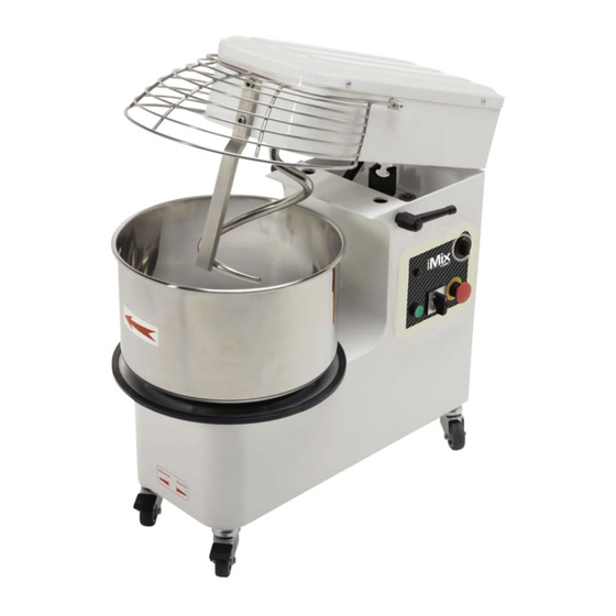
iM 5
iM 8
iM 12
iM 18
iM 25
iM 38
iM 44
Cod.73340240
Ver.: A6
Manuale di istruzioni
Instructions manual
Manual d'instructions
Bedienungsanleitung
iM 12/2
iM 18/2
iM 25/2
iM 38/2
iM 44/2
Numeri di matricola / Serial numbers :
iM R12/2
iM R18/2
iM R25/2
iM R38/2
iM R44/2
Impastatrice a spirale
Spiral mixer
Petrin
Spiralknetmaschine
Werbung
Kapitel
Inhaltsverzeichnis

Verwandte Anleitungen für Moretti Forni iM 5

Inhaltszusammenfassung für Moretti Forni iM 5
- Seite 1 Manuale di istruzioni Instructions manual Manual d’instructions Bedienungsanleitung iM 5 iM 12/2 iM R12/2 iM 8 iM 18/2 iM R18/2 iM 12 iM 25/2 iM R25/2 iM 18...
-
Seite 3: Dichiarazione Di Conformità
- m a i l : m a r k e t i n g @ m o r e t t i f o r n i . c o m Dichiarazione di conformità Noi, MORETTI FORNI SPA., Via A. Meucci n. 4 – 61037 Mondolfo (Pesaro) - Italia, dichiariamo sotto nostra esclusiva responsabilità che il prodotto: Mod. - Seite 4 We declare under sole responsability that the products to which this declaration relates is in conformity with the following standards <> following the provisions of the directives<>.
-
Seite 5: Inhaltsverzeichnis
SOMMARIO CAPITOLO 1 INFORMAZIONI GENERALI..............4 CAPITOLO 2 INSTALLAZIONE ................11 CAPITOLO 3 MESSA IN FUNZIONE ..............13 CAPITOLO 4 USO ....................16 CAPITOLO 5 MANUTENZIONE ................19 CAPITOLO 6 DEMOLIZIONE DELLA MACCHINA ..........21 CAPITOLO 7 SERVIZIO POST - VENDITA.............. 22 Prefazione Questo manuale è... -
Seite 6: Capitolo 1 Informazioni Generali
· Trasmissione a catena con motoriduttore a bagno d'olio. · Parti in movimento montate su cuscinetti a sfera a tenuta stagna. · Piedini di appoggio in gomma (mod. iM 5 - iM 8), ruote di cui 2 con freno (mod. da iM 12 a iM 44) ·... - Seite 7 FIG. 1 iM 5; iM 8 iM 12; iM 18; iM 25; iM 38; iM 44 iM R12; iM R18; iM R25; iM R38; iM R44 IMPASTATRICE A SPIRALE - Serie iM Manuale d’uso e manutenzione...
-
Seite 8: Caratteristiche Tecniche
1.3 Caratteristiche tecniche Modello Capacità d’impasto Capacità farina Volume vasca Dim. vasca Potenza motore Volt Dimensioni mm Peso iM 5 237 x 160 0,37 230/50 540 x 260 x 527 iM 5 237 x 160 0,37 400/50/3 540 x 260 x 527... -
Seite 9: Schemi Elettrici
1.4 Schemi elettrici COLLEGAMENTO MONOFASE iM 5-8 COLLEGAMENTO MONOFASE iM 12-18-25-38-44 IMPASTATRICE A SPIRALE - Serie iM Manuale d’uso e manutenzione... - Seite 10 COLLEGAMENTO TRIFASE iM 12-18-25-38-44 COLLEGAMENTO TRIFASE 2 VEL. iM 12-18-25-38-44 IMPASTATRICE A SPIRALE - Serie iM Manuale d’uso e manutenzione...
- Seite 11 Legenda schemi elettrici FIG. 2 COLLEGAMENTI MONOFASE E TRIFASE = Interruttore generale = Trasformatore = Fusibile = Protezione termica motore = Sensore di prossimità = Fine corsa di sicurezza STOP = Pulsante arresto START = Pulsante avviamento K18M = Contattore = Lampada di funzionamento = Motore 1.5 Zona occupata dall'operatore...
-
Seite 12: Avvertenze Per La Sicurezza
1.7 Avvertenze per la sicurezza INFORMAZIONI Leggere attentamente queste istruzioni prima di utilizzare la macchina. ATTENZIONE Allo scopo di prevenire condizioni di pericolo e/o possibili ferimenti causati da: corrente elettrica, organi meccanici, incendio, o di natura igienica, devono essere osservate le seguenti avvertenze per la sicurezza: A) Mantenere in ordine il proprio posto di lavoro. -
Seite 13: Capitolo 2 Installazione
CAPITOLO 2 INSTALLAZIONE 2.1 Prescrizioni a carico dell'utente Le condizioni ambientali del luogo dove viene installata la macchina devono avere le seguenti caratteristiche: · Essere prive di umidità. · Fonti idriche e di calore adeguatamente distanti. · Ventilazione ed illuminazione adeguata e rispondenti alle norme igieniche e di sicurezza previste dalle leggi vigenti. -
Seite 14: Collegamento Elettrico
In caso d'instabilità della macchina dovute all'irregolarità del pavimento, spessorare i piedini o le ruote con dei pezzi di lastra di gomma dura. Per le macchine dotate di ruote assicurarsi che quest'ultime siano state frenate premendo verso il basso fino a bloccare la leva A (FIG. -
Seite 15: Capitolo 3 Messa In Funzione
Le macchine sono dotate dei seguenti dispositivi di comando e di sicurezza: 3.1 Dispositivi di comando Macchine con alimentazione monofase o trifase (mod. iM 5-iM 8) (FIG. 5): A - Pulsante verde 1 Avviamento (A) B - Pulsante rosso 2 Arresto (B) Macchine con alimentazione monofase 1 velocità, trifase 1 velocità... - Seite 16 Nota: I dispositivi di sicurezza M,M1-N-O sono installati esclusivamente sulle macchine con testa sollevabile e vasca estraibile (richiamate come modello A). Nei modelli con testa fissa il dispositivo di verifica sollevamento griglia di protezione è posto all’interno della testata. ATTENZIONE I dispositivi di sicurezza verificati singolarmente sono efficienti quando: ·...
-
Seite 17: Verifica Funzionale
è pronta per la verifica funzionale. 3.3 Verifica funzionale Macchina monofase e trifase (mod. iM 5 - iM 8): AVVIAMENTO: premere il pulsante verde A per avviare sia la vasca che la spirale. -
Seite 18: Capitolo 4 Uso
CAPITOLO 4 USO Prima d'iniziare ogni ciclo di lavoro accertarsi che la macchina sia perfettamente pulita in particolare, le superfici di contatto della vasca, della spirale e del piantone centrale, che vanno trattati con detersivi compatibili con i prodotti alimentari. Qualora necessario procedere alla pulizia secondo le modalità... - Seite 19 FIG. 10-11 4.2.2 Riposizionamento della vasca e della testa Ultimata l'operazione di pulizia, rimontare la vasca assicurandosi che i 4 perni sottostanti (FIG. 11) vengano correttamente inseriti all'interno dei fori K della macchina, bloccare la vasca ruotando in senso antiorario il disco O. Riposizionare orizzontalmente la testa premendola progressivamente verso il basso (FIG.
- Seite 20 4.4 Uso della macchina dotata di temporizzatore Il temporizzatore o timer è un dispositivo elettromeccanico che consente di programmare da 1 a 30 minuti il tempo di lavoro della macchina. · Programmare il tempo di lavoro ruotando la manopola F (FIG. 6-7) nella posizione desiderata.
-
Seite 21: Capitolo 5 Manutenzione
CAPITOLO 5 MANUTENZIONE ATTENZIONE Prima di eseguire qualsiasi intervento di manutenzione o pulizia, staccare la spina dalla presa di alimentazione elettrica. In caso di malfunzionamento o di guasto della macchina rivolgersi esclusivamente ai centri di assistenza autorizzati dal costruttore (ved. CAP. 7). 5.1 Pulizia La pulizia dev'essere eseguita alla fine di ogni utilizzo in osservanza alle norme igieniche e a tutela della funzionalità... - Seite 22 FIG. 14-15 5.3 Ingrassaggio catene Dopo aver svitato le viti di fissaggio, togliere i pannelli superiore P e posteriore V, depositare all'interno delle catene S-T (FIG. 15-16) una ragionevole quantità di grasso idoneo o sufficiente ad assicurare la lubrificazione di tutte le maglie delle catene. Ad operazione completata rimontare i due pannelli e riavvitare le viti.
-
Seite 23: Capitolo 6 Demolizione Della Macchina
5.4 Possibili anomalie ANOMALIA CAUSA SOLUZIONE La macchina non si · Mancanza di energia elettrica · Verificare il contatore avvia nella rete generale, la presa, la spina e il cavo di alimentazione · Il pulsante Arresto- · Ruotare il pulsante nel Emergenza è... -
Seite 24: Capitolo 7 Servizio Post-Vendita
CAPITOLO 7 SERVIZIO POST-VENDITA 7.1 Parti di ricambio Per la richiesta di parti di ricambio riferirsi alle FIG. 17-22. ATTENZIONE Vi raccomandiamo di usare solo pezzi di ricambio originali. STATI CEE: Rivolgersi esclusivamente al proprio rivenditore. IMPASTATRICE A SPIRALE - Serie iM Manuale d’uso e manutenzione... - Seite 25 SUMMARY CHAPTER 1 GENERAL INFORMATION ..............24 CHAPTER 2 INSTALLATION .................. 31 CHAPTER 3 FUNCTIONING .................. 33 CHAPTER 4 USAGE ....................36 CHAPTER 5 MAINTENANCE .................. 39 CHAPTER 6 DEMOLITION OF THE MACHINE ............41 CHAPTER 7 AFTER SALE SERVICE ..............42 Prefix This manual is specifically for the installation, use and maintenance of spiral mixers.
-
Seite 26: Chapter 1 General Information
· The moving parts are on ball bearing. · Type feet (from models iM 5 and iM 8), set of wheels (for models from iM 12 to iM 44) · Operation with single-phase or threephase motor, one speed; on request: threephase motor with two speeds and timer (apart from models iM 5 and iM 8). - Seite 27 PICT. 1 iM 5; iM 8 iM 12; iM 18; iM 25; iM 38; iM 44 iM R12; iM R18; iM R25; iM R38; iM R44 SPIRAL MIXER - iM Series Operating manual...
-
Seite 28: Technical Characteristics
1.3 Technical characteristics Model Kneading capacity Flour capacity Bowl volume Bowl dimension Motor power Volt Dimensions mm Weight iM 5 237 x 160 0,37 230/50 540 x 260 x 527 iM 5 237 x 160 0,37 400/50/3 540 x 260 x 527... -
Seite 29: Electrical Schemes
1.4 Electrical schemes SINGLE-PHASE CONNECTION iM 5-8 SINGLE-PHASE CONNECTION iM 12-18-25-38-44 SPIRAL MIXER - iM Series Operating manual... - Seite 30 THREE-PHASE CONNECTION iM 12-18-25-38-44 THREE-PHASE CONNECTION 2 SPEEDS iM 12-18-25-38-44 SPIRAL MIXER - iM Series Operating manual...
- Seite 31 Electrical schemes PICT. 2 SINGLE-PHASE AND THREE-PHASE CONNECTION = General switch = Transformer = Fuse = Thermoproction of the engine = Safety photocell = Safety limit switch STOP = Stop button START= Operating button K18M = Contactor = Operating light = Engine 1.5 Operating area In normal working conditions and to have the best exploration of the potentiality of the...
-
Seite 32: Security Indications
1.7 Security indications INFORMATION Carefully read the instruction before using the machine. WARNING The avoid dangerous condition and/or possible injuries caused from: electric current, mechanical parts, fire or hygienical problems, you must follow the security indications step by step. A) Keep in order your working area. Disorder can cause dangerous accidents. B) Consider environmental conditions. -
Seite 33: Chapter 2 Installation
CHAPTER 2 INSTALLATION 2.1 Instructions for the user The environmental conditions in which the machine must be installed must follow these characteristics: · Be dry · The machine is constructed to have IPXI protection level. · Water and heat sources at safe distance ·... -
Seite 34: Electrical Connections
PICT. 3 PICT. 4 2.3 Electrical connections The connections type Y of the machine with the electric network is made by means of an operation cable, which is provided with a plug only in the singlephase model. As far as the three-phase machines are concerned it is necessary to put together the cable and a normalized and polarized plug (the distinction between phase and neutral must be unequivocal), and verify that the rotation way of the bowl is the same indicated by the... -
Seite 35: Chapter 3 Functioning
CHAPTER 3 FUNCTIONING The machines are provided with the following operating and safety devices: 3.1 Operating devices Single-phase or Threephase machines (iM 5 - iM 8) (PICT. 5): A -Green button 1 operating B -Red button 2 Stop Single-phase or Three-phase machines (the rest of the models) (PICT. 6-7):... - Seite 36 WARNING The single safety device are efficient when: · On raising the protetion I (PICT. 8) the machine stops. · On raising the top (by means of the check pin M and/or taking off bowl the machine does not start. ·...
- Seite 37 3.3 Working test machine Single-phase or three-phase machine (mod. iM 5 - iM 8): OPERATING: push the green button A to start the bowl and the spiral. STOP: push the red button to stop the bowl and the spiral. Single-phase or three-phase machine (1-2 vel.) OPERATING: rotate the knob of the switch C in position 1, set the time of mixing by the timer F, push the green button D to start the bowl and the spiral.
-
Seite 38: Chapter 4 Usage
CHAPTER 4 USAGE Before starting work make sure that the machine is perfectly clean in particular, the surfaces of bowl, the spiral and of the central column that have contact with the food products. If necessary clean them following indications at 5.1. 4.1 Usage of the machine with fixed top and bowl After lifted up the protection I, pour in the bowl all the required ingredients, push down the protection, press the button to start A or D. -
Seite 39: Operating
PICT. 10-11 4.2.2 Repositioning of the bowl and top Once the cleaning is done, put the bowl back on, and make sure that the four pins underneath (PICT. 11) are correctly fixed in the four holes K of the machine; then block the bowl rotating clockwise the disk O. - Seite 40 4.4 Usage of the machine provided with timer The timer is an electromechanical device that allows to program from 1 to 30 minutes. · The work-time of the machine by rotating the knob 0 in the desired position (PICT. 13). ·...
-
Seite 41: Chapter 5 Maintenance
CHAPTER 5 MAINTENANCE WARNING Before effecting any kind of maintenance or cleaning you must take out the plug. In any case of malfunctioning or damage of the machine you must apply for authorized assistance from the manufacturer (see Chapter 7). 5.1 Cleaning The cleaning must be done every time the machine has been used following all the rules to prevent malfunctioning of the machine and for hygienic purposes. - Seite 42 PICT. 14-15 5.3 Lubrificating the chains After unscrewing the fixing screws, take away the upper P and the back V panels, put on the ichains S-T (PICT. 15-16) a reasonable amount of proper grease, sufficient to lubricate all the links of the chain. Once this is done, mount the two panels and secure again with screws.
-
Seite 43: Possible Anomalies
5.4 Possible anomalies ANOMALY CAUSE SOLUTION The machine does · Lack of energy in the · Check the general switch, not start power grid the plug, the tap and the feeding cable · The Emergency stop button · Rotate the button following in blocked the direction of the arrow ·... -
Seite 44: Chapter 7 After Sale Service
CHAPTER 7 AFTER SALE SERVICE 7.1 Spare parts For a demand of spare parts, see the PICT. 17-22. WARNING We advise you to fit original spare parts only. EEC countries: Contact exclusively place of purchase. SPIRAL MIXER - iM Series Operating manual... - Seite 45 SOMMAIRE CHAPITRE 1 INFORMATIONS GENERALES ............44 CHAPITRE 2 INSTALLATION ................. 51 CHAPITRE 3 MISE EN MARCHE ................53 CHAPITRE 4 UTILISATION ..................56 CHAPITRE 5 ENTRETIEN ..................59 CHAPITRE 6 DEMOLITION DE LA MACHINE ............61 CHAPITRE 7 SÈRVICE APRES VENTE ..............62 Preface Ce manuel est adressé...
-
Seite 46: Chapitre1 Informations Generales
CHAPITRE1 INFORMATIONS GENERALES 1.1 Garantie La garantie est valable 1 an à partir de la reception du reçu fiscal delivré au moment de l'achat. Pendant se temps, seront remplacés ou réparés gratuitement les details qui pour des raisons bien évaluées et sans équivoque résultent de fabrication defecteuse, à éxception des parties élèctriques et celles exposées à... - Seite 47 FIG. 1 iM 5; iM 8 iM 12; iM 18; iM 25; iM 38; iM 44 iM R12; iM R18; iM R25; iM R38; iM R44 PÉTRIN À SPIRALE - MODÈLE iM Manuel d’utilisation...
-
Seite 48: Carateristiques Techniques
Volume Dimension Puissance Volt Dimensions Poids de farine de la cuve de la cuve du moteur iM 5 237 x 160 0,37 230/50 540 x 260 x 527 iM 5 237 x 160 0,37 400/50/3 540 x 260 x 527... - Seite 49 1.4 Schémas éléctriques BRANCHEMENT MONOPHASÉE iM 5-8 BRANCHEMENT TRIPHASÉE iM 12-18-25-38-44 PÉTRIN À SPIRALE - MODÈLE iM Manuel d’utilisation...
- Seite 50 BRANCHEMENT TRIPHASÉE iM 12-18-25-38-44 BRANCHEMENT TRIPHASÉE 2 VIT. iM 12-18-25-38-44 PÉTRIN À SPIRALE - MODÈLE iM Manuel d’utilisation...
- Seite 51 Schémas éléctriques FIG. 2 BRANCHEMENT MONOPHASÉE ET TRIPHASÉE = Interrupteur général = Transformateur = Fusible = Protection termique moteur = Photocellule de Securité = Butée de fin de course STOP = Bouton arret START = Bouton mise en marche K18M = Contacteur = Ampoulle de fonctionnement 1.5 Zone occupée par l'opérateur Dans de conditions normales de travail et pour une exploitation optimale de la puissance...
- Seite 52 1.7 Indication des securité INFORMATIONS Lire attentivement ces instrution avant d'employer la machine. ATTENTION Dans le but de prévenir les conditions de danger et/ou éventuelles blessures provoquées par: le courant éléctrique, parties mecaniques, incendie, ou d'origine hygiénique, les normes de securité suviantes doivent etre obsérvées: A) Le poste de travail doit etre maintenu en oredre.
-
Seite 53: Chapitre 2 Installation
CHAPITRE 2 INSTALLATION 2.1 Prescription à charge de l'usager Les conditions ambiantes du milieu ou est disposés la machine ont les caracteristiques suivantes: · Etre sec · La machine est construite de façon à avoir un niveau de protection IPXI ·... -
Seite 54: Positionnement De La Machine
avec des plaques de gomme dure. Pour les machines fournies de roues, s'assurer qu'elles aient été freinées en appuyant vers le bas jusqu'à bloquer le levier A (FIG. 4). Note: Tous les details relatifs à l'emballage doivent etre éxécutés selon les lois en vigueur. FIG. -
Seite 55: Chapitre 3 Mise En Marche
Les machines sont munies des dispositifs de commande et de sécurité suivants: 3.1 Dispositifs de commande Machines à alimentation monophasée ou triphasée (iM 5 - iM 8) (FIG. 5): A - Bouton poussoir vert 1 Mise en marche B - Bouton poussoir rouge 2 Arret Machines à... - Seite 56 ATTENTION Led dispositifs de sécurité, vérifiées un par un, sont efficaces lorsque: · En soulevant la protection I (FIG. 8) la machine s'arrete. · En soulevant la tete (débloquée de son axe M) et/ou en retirant la cuve la machine ne se met pas en marche.
-
Seite 57: Mise En Service
éléctrique, la machine est prete pour etre verifié. 3.3 Essai de fonction Machine mod. iM 5 - iM 8: MISE EN SERVICE: appuyer sur le bouton poussoir vert A pour faire fonctionner aussi bien la cuve que la vis spiralée. -
Seite 58: Chapitre 4 Utilisation
CHAPITRE 4 UTILISATION Avant de commencer chaque cycle de travail, verifier que la machine soit parfaitement nettoyée en particulier les surfaces de contact de la cuve, de la spirale et du bras central, avec les produits alimentaires. Dans le cas ou il est necessaire proceder au nettoyage suivant les modalités 5.1. - Seite 59 FIG. 10-11 4.2.2 Respositionnement de la cuve et la tete Dés l'opération de nettoyage terminée, remonter la cuve en s'assurant que les guidages du dessous (FIG. 11) soient correctement insérés à l'intérieur des trous M de la machine, bloquer la cuve en tournant dans le sens contraire des aiugilles d'une montre le disque L. Repositionner horizontalement la tete en l'appuyant progressivement vers le bas (FIG.
- Seite 60 4.4 Utilisation de la machine munie de temporisation La temporisation ou timer est un dispositif électromécanique qui permet de programmer de là 30 minutes le temps de travail de la machine. · Programmer le temps de travail en tournant poignée 0 (FIG. 13) dans la position dèsirèe. ·...
-
Seite 61: Chapitre 5 Entretien
CHAPITRE 5 ENTRETIEN ATTENTION Avant d'éxécuter n'importe quelle intervention d'entretien, nettoyage y compris, il faut debrancher la prise d'alimentation éléctrique. En cas de mauvais fonctionnement ou de panne de la machine s'adresser exclusivement aux centres d'assistance autorisés par le constructeur (voir chap. 7). 5.1 Nettoyage La nettoyage doit etre éxécuté... - Seite 62 FIG. 14-15 5.3 Graissage des chaines Après avoir dévissé les vis de fixation, enlever les panneaux superieur P et inferieur V, déposer à l'interieur des chaines S-T (FIG. 15-16) une quantité de graisse raisonnable et approprié, suffisante afin d'assurer la lubrification de tous les maillons des chaines. A la fin de l'opération remonter led deux panneaux et revisser les vis.
-
Seite 63: Chapitre 6 Demolition De La Machine
5.4 Possible anomalies ANOMALIE CAUSE SOLUTION La machine ne se met · Manque d’énergie électrique · Vérifier la cantacteur pas en marche sur le secteur général, la fiche, la prise et le cable d’alimentation · Le bouton poussoir Arret d’urgence est bloquè ·... -
Seite 64: Chapitre 7 Sèrvice Apres Vente
CHAPITRE 7 SÈRVICE APRES VENTE 7.1 Pièces de rechange Pour le domande des pièces de rechange, se rapporter à les FIG. 17-22. ATTENTION Nous vous recommendons d'employer pieces detachees originales seulement. Etats de la CEE: S'adresser exclusivament au propre revendeur. PÉTRIN À... - Seite 65 SUMMARISCH KAPITEL 1 ALLGEMEINE INFORMATIONEN ............64 KAPITEL 2 INSTALLATION .................. 71 KAPITEL 3 IN BETRIEBNAHME ................73 KAPITEL 4 GEBRAUCH ..................76 KAPITEL 5 WARTUNG..................79 KAPITEL 6 VERSCHROTTUNG DER MASCHINE ..........81 KAPITEL 7 SERVICE NACH VERKAUF ............... 82 Vorwort Dieses Handbuch ist an alle gerichtet, die mit der Installation, Gebrauch und Wartung der Teigmaschinen beauftragt sind und so auf die beste Art die Charakteristiken des Produktes nutzen können.
-
Seite 66: Kapitel1 Allgemeine Informationen
KAPITEL1 ALLGEMEINE INFORMATIONEN 1.1 Garantie Die Garantiedauer beträgt 1 Jahr und gilt mit Erhalt der Steuerquittung bei Erwerb. Innerhalb dieses Zeitraumes werden kostenfrei und nur ab unserem Werk die Teile ersetzt und repariert, die zweifelsfrei auf Fabrikationsfehler zurückzuführen sind, ausgenommen sind elektrische Bau- und Verschleissteile. - Seite 67 BILD 1 iM 5; iM 8 iM 12; iM 18; iM 25; iM 38; iM 44 iM R12; iM R18; iM R25; iM R38; iM R44 SPIRALTEIGKNETMASCHINE - MODELL iM Bedienungsanleitung...
-
Seite 68: Technische Charakteristika
Fassungsvermögen Modell Teigmasse Mehlmenge Abmessungen Motorleistung Volt Abmessungen Gewicht Behälter behälter iM 5 237 x 160 0,37 230/50 540 x 260 x 527 iM 5 237 x 160 0,37 400/50/3 540 x 260 x 527 iM 8 260 x 200... - Seite 69 1.4 Elektroschemen SCHALTPLAN EINPHASESCHALTUNG iM 5-8 SCHALTPLAN EINPHASESCHALTUNG iM 12-18-25-38-44 SPIRALTEIGKNETMASCHINE - MODELL iM Bedienungsanleitung...
- Seite 70 SCHALTPLAN DREIPHASESCHALTUNG iM 12-18-25-38-44 SCHALTPLAN DREIPHASESCHALTUNG 2 GES. iM 12-18-25-38-44 SPIRALTEIGKNETMASCHINE - MODELL iM Bedienungsanleitung...
- Seite 71 Elektroschemen BILD 2 SCHALTPLAN EIN - UND DREIPHASESCHALTUNG = Hauptschalter = Stromwandler = Schmelzsicherung = Termoshutzmotor = Notphotozelle = Notende schalter STOP = Haltknopf START = Gagknopf K18M = Kontaktgeber = Betriebs anzeiger = Motor 1.5 Arbeitsbereich Unter normalen Arbeitsbedingungen benoetigt der Arbeiter zue optimalen Nutzung der Maschinenkfraft den Platz wie in BILD 2 dargestellt.
-
Seite 72: Sicherheitsanweisungen
1.7 Sicherheitsanweisungen INFORMATIONEN Vor in Betriebnahme aufmerksam die Gebrauchseinweisung lesen. ACHTUNG Um eventuellen Gefahrenquellen vorzubeugen, die auf Storm, mech. Teile, Feuer oder hygienische Natur zurückzufuhren führen sind, müssen folgende. Sicherheitsbestimmungen eingehalten werden: A) Den Arbeitsplatz in Ordnung halten. Unordnung Feuergefahr birgt. B) Die Umgebungsbedingungen beachten. -
Seite 73: Kapitel 2 Installation
KAPITEL 2 INSTALLATION 2.1 Vorschriften für de Benutzer Die Bedingungen des Ortes, wo die Maschine aufgestellt wird, sollten folgende Eigenschaften besitzen: · Trocken. · Die Machine wird gebaut, um einen Schutzstand IPXI zu haben. · Wasser- und Hitzequellen in entsprechender Entfernung. ·... -
Seite 74: Elektroanschluss
Anmerkung: Alla relativen Einzelteile müssen gesetzmässig lackiert sein. BILD 3 BILD 4 2.3 Elektroanschluss Die Maschine wird durch Zuleitungskabel an das elektrische Netz angeschlossen (Anschluß Typ Y), welches nur bei der Einphasen-Ausführung mit Stecker ausgestattet ist. Bei den Maschinen mit Dreiphasenmotor ist es erforderlich, am Kabelendverschluss einen normalisierten und polarisierten Stecker anzubringen (wobei der Unterschied zwischen Phase und Nullpunkt deutlich erkennbar sein. -
Seite 75: Kapitel 3 In Betriebnahme
Die maschinen sind mit den folgenden Steuerinrichtungen und Sicherheitsvorrichtungen ausgestattet: 3.1 Steuereinrichtungen Maschine mit Einphasen-order Drei-phasenantrieb (iM 5 - iM 8) (BILD 5): A - Grüner Kopf 1 Anlauf B - Roter Knopf 2 Anhalt Maschinene mit Einphasen-order Dreiphasenenatrieb (die anderen Modelle) (BILD 6-7): C - Hauptschalter D - Grüner Knopf Anlauf... - Seite 76 ACHTUNG Die Sicherheitsvorrichtungen sind bei der jeweiligen Prüfungals leistungsfähig zu betrachten, wenn: · Indem man die Abdeckun F (BILD 8) aufzieht, die Maschine anhält. · Indem den Kopf bei entriegeltem Stift H hebt, bzw das Becken herauszieht, die Maschine nicht anläuft. ·...
- Seite 77 3.3 Betriebstest Maschine Mod. iM 5 - iM 8: ANLAUF: grünen Knopf A drükken, um sowohl das Becken, als auch die Spirale in Betrieb zu setzen. ANHALT: roten Knopf B drükken, um sowohl das becken, als auch die Spirale anzuhalten.
-
Seite 78: Kapitel 4 Gebrauch
KAPITEL 4 GEBRAUCH Vor Beginn eines Arbeitszyklus sicherstellen, daß die Maschine und besonders die Oberflächen der Wanne, der Spirale und der Steuersäule mit Kontakt der Nahrungsmittel, richtig gesäubert sind. Sollte es nötig sein, nach den vorgegebenen Modalitäten 5.1 vorgehen. 4.1 Gebrauch der Maschine mit festem Haupt und Wanne Nach Anheben des Schutzes F, die Zutaten in gewuenschter Menge in die Wanne geben, den Schutz absenken, den Startknopf A oder D drücken. -
Seite 79: Becken Und Kopf Wiederaufstellen
BILD 10-11 4.2.2 Becken und Kopf wiederaufstellen Nach der Reinigung, beim Aufstellen des Beckens darauf achten, daß die 4 darunterliegenden Stifte (BILD 11) durch die jeweiligen in der Maschine angebrachten Löcher M richtig gesteckt werden; das Becken wird dann befestigt, indem man Scheibe L entgegen dem uhrzeigersinn dreht. -
Seite 80: Gebrauchanweisung Für Die Maschine Mit Zeitregler
4.4 Gebrauchanweisung für die Maschine mit Zeitregler Der Zeitregler bzw.timer ist eine elektromechanische Vorrichtung, welche ermöglicht, die Betriebszeit der Maschine von 1 bis 30 Minuten zu programmieren. · Die Betriebszeit programmieren, indem man Waehler 0 (BILD 13) auf die gewünschte Stellung dreht. -
Seite 81: Kapitel 5 Wartung
KAPITEL 5 WARTUNG ACHTUNG Vor jeglichen Wartungsarbeiten, Reinigung eingenommen den Stecker ziehen. Für den Fall, daß die Maschine schlecht oder gar nicht funktionniert, sollte sich ausschliesslich an den Hersteller gewandt werden (siehe Kap. 7). 5.1 Reinigung In Anbetracht der Hygienevorschriften und dem allgemeinen Funktionieren der Maschine muss die Reinigung nach jedem Gebrauch vorgenommen werden. -
Seite 82: Einfettung Der Ketten
BILD 14-15 5.3 Einfettung der Ketten Nach Lösen der Befestigungs-schrauben die vordere Platte P und hintere Platte V abnehmen, im Inneren der Ketten S-T eine angemessene Menge von richtigem Fett (BILD 15 UND 16), ausreichend um eine Schmierung aller kettengliedern zu gewährleisten. Nach abgeschlossener Arbeit die zwei Platten wieder montieren und die Schrauben anziehen. -
Seite 83: Mögliche Fehler
5.4 Mögl iche Fehler FEHLER URSACHE LOESUNG Die maschine haelt · Stromausfall · Haupschalter, Stecker, waehrend des Steckdose und Speise-Kabel Betriebs an pruefen · Der Notausschalter ist · Waehler in Pfeilrichtung blockiert drehen · Des Schutzgitter bzw. der · Schutzgitter u. Kopf korrekt Kopf sind gehoben nach unten verstellen ·... -
Seite 84: Kapitel 7 Service Nach Verkauf
KAPITEL 7 SERVICE NACH VERKAUF 7.1 Ersatzteile Um Ersatzteile zu verlangen, sich auf die BILD 17-22. ACHTUNG Wir empfehlen nur den gebrauch der originalen ersatzteile. EWG-Staaten: Ausschliesslich an den eigenen Verkäufer wenden. SPIRALTEIGKNETMASCHINE - MODELL iM Bedienungsanleitung... - Seite 85 PICT. 17 Spare parts for mixer with fixed top and bowl mod. iM 5-8 FIG. 17 Pièces de rechange pour petrisseuse avec tete et cuve fixe mod. iM 5-8 BILD 17 Ersatzteile für die Teigknet-maschine mit gestem Kopl und Becken mod. iM 5-8...
- Seite 86 FIG. 18 Parti di ricambio impastatrice con testa e vasca fissa mod. iM 12-18 PICT. 18 Spare parts for mixer with fixed top and bowl mod. iM 12-18 FIG. 18 Pièces de rechange pour petrisseuse avec tete et cuve fixe mod. iM 12-18 BILD 18 Ersatzteile für die Teigknet-maschine mit gestem Kopl und Becken mod.
- Seite 87 FIG. 19 Parti di ricambio impastatrice con testa e vasca fissa mod. iM 25-38-44 PICT. 19 Spare parts for mixer with fixed top and bowl mod. iM 25-38-44 FIG. 19 Pièces de rechange pour petrisseuse avec tete et cuve fixe mod. iM 25-38-44 BILD 19 Ersatzteile für die Teigknet-maschine mit gestem Kopl und Becken mod.
- Seite 88 FIG. 21 Parti di ricambio impastatrice con testa sollevabile e vasca estraibile mod. iM R12-R18 PICT. 21 Spare parts for mixer with raising top and removable bowl mod. iM R12-R18 FIG. 21 Pièces de rechange pour petrisseuse avec tete soulevable et cuve extractible mod. iM R12-R18 BILD 21 Ersatzteile für die Teigknet-maschine mit hebbarem Kopl und herauszichbarem Becken mod.
- Seite 89 FIG. 22 Parti di ricambio impastatrice con testa sollevabile e vasca estraibile mod. iM R25-R38-R44 PICT. 22 Spare parts for mixer with raising top and removable bowl mod. iM R25-R38-R44 FIG. 22 Pièces de rechange pour petrisseuse avec tete soulevable et cuve extractible mod. iM R25-R38-R44 BILD 22 Ersatzteile für die Teigknet-maschine mit hebbarem Kopl und herauszichbarem Becken mod.
- Seite 90 DESCRIZIONE DESCRIZIONE PROT. VASCA MOTORE BULLONE ASTA ROMPIPASTA TRIANGOLO ASTA ROMPIPASTA AZIONATORE FINE CORSA VASCA MICRO CUSCINETTO SUPPORTO VASCA BULLONE SUPPORTO VASCA BULLONE CORONA VASCA CUSCINETTO CORONA SUPPORTO TESTATA ALBERO VASCA RONDELLA SUPPORTO TESTATA CATENA VASCA BULLONE SUPPORTO TESTATA IMPIANTO ELETTRICO GIUNTO DI TRASMISSIONE RUOTA CON FRENO MOLLA A GAS...
- Seite 91 DESCRIZIONE DESCRIZIONE FERMO BATTUTA DISCO MOBILE BULLONE FISSAGGIO ALBERO RIDUTT. SEGER ALBERO VASCA DADO FISSAGGIO RIDUTTORE GRANO PIGNONE SPIRALE RONDELLA FISSAGGIO RIDUTTORE DISTANZIALE SUPPORTO SPIRALE BULLONE FISSAGGIO RIDUTTORE RONDELLA RONDELLA CUSCINETTO SUPPORTO SPIRALE RONDELLA FISS. ALBERO RIDUTT. 10 X 40 CHIAVETTA ALBERO SPIRALE RUOTA VITE AUTOFORANTE CARTER TESTATA...
- Seite 92 Note / Notes / Nòtes / Note...