Bender 107TD47 Handbuch
Isometer
isolations-überwachungsgerät
mit transformatorüberwachung
Inhaltsverzeichnis
Handbuch/Manual
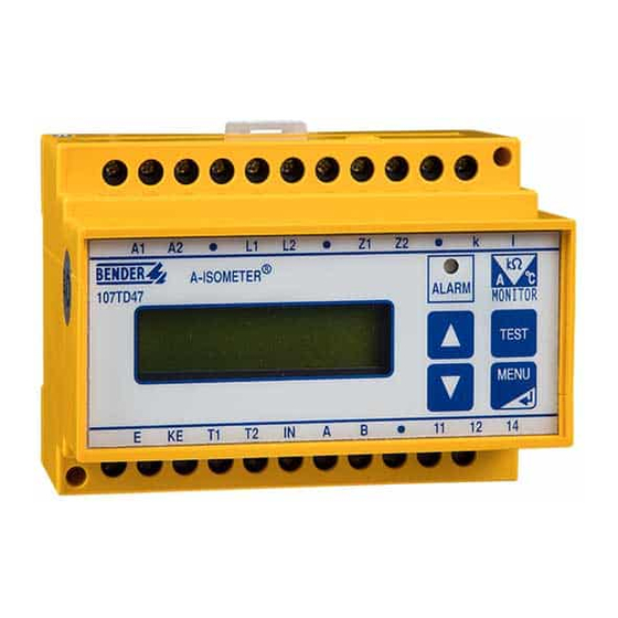
ISOMETER®107TD47
Isolations-Überwachungsgerät
mit Transformatorüberwachung
Bestimmungsgemäße Verwendung
Das 107TD47 ist ein kombiniertes Überwachungsgerät zur
Isolationsüberwachung eines AC IT-Systems
•
Laststromüberwachung eines IT-System-Transformators
•
bis 50 A
Überwachung eines IT-System-Transformators auf unzu-
•
lässige Erwärmung.
Das Gerät ist besonders geeignet zur Überwachung der Strom-
versorgung von medizinisch genutzten Bereichen nach DIN VDE
0100-710 (VDE 0100 Teil 710): 2002-11 und IEC 60364-7-
710:2002-11.
Sicherheitshinweise allgemein
Montage, Anschluss und Inbetriebnahme nur durch Elektrofach-
kraft! Beachten Sie unbedingt:
die bestehenden Sicherheitsvorschriften und
•
das beiliegende Blatt "Wichtige sicherheitstechnische Hin-
•
weise für Bender-Produkte".
Sicherheitshinweise gerätespezifisch
Trennung vom IT-System beachten!
Vor Isolations- und Spannungsprüfungen an der
Anlage muss das Isolationsüberwachungsgerät
für die Dauer der Prüfung vom IT-System getrennt
VORSICHT
sein. Andernfalls kann das Gerät Schaden neh-
men.
Für den Einsatz von ISOMETER®n in IT-Systemen
gilt generell, dass nur ein aktives ISOMETER® in ei-
nem galvanisch miteinander verbundenen Sys-
tem angeschlossen sein darf.
Funktionsbeschreibung
Isolationsüberwachung
Das Gerät misst den Isolationswiderstand in 1- oder 3-phasigen
AC IT-Systemen, die auch Gleichspannungsanteile enthalten dür-
fen. Die Anpassung an Netzableitkapazitäten (max. 5 μF) erfolgt
automatisch.
Laststrommessung
Bei AC-Systemen wird der Laststrom über einen Stromwandler
STW2 erfasst. Bei 3AC-Systemen wird über drei Stromwandler
STW2 und ein CMS460-D4-2 Laststrom-Auswertegerät der höchs-
te Wert des Laststromes ermittelt.
Temperaturmessung
Die Temperatur in der Transformatorenwicklung wird über Kalt-
leiter oder Öffnerkontakte erfasst.
Auswertung
Ist einer der erfassten Werte nicht innerhalb der Grenzwerte, so
wird ein Alarm (Sammelmeldung) ausgelöst. Die LED „ALARM"
leuchtet, das Alarmrelais schaltet und im LC-Display erscheint
eine Meldung. Über den BMS-Bus wird dieser Alarm an andere
Bender-Geräte, wie z.B. eine Melde- und Prüfkombination, wei-
tergegeben.
107TD47_D00091_00_M_DEEN / 10.2016
Insulation Monitoring Device
Deutsch
with transformer monitoring
Intended Use
The ISOMETER
the insulation resistance of AC IT systems;
•
the load current of IT system transformers up to 50 A;
•
the temperature of the IT system transformers.
•
The ISOMETER
plies in medical locations according to DIN VDE 0100-710 (VDE
0100 part 710): 2002-11 and IEC 60364-7-710:2002-11.
Safety Information
Installation, connection and commissioning of electrical equip-
ment shall only be carried out by skilled persons!
Particular attention shall be paid to:
the current safety regulations and
•
the enclosed sheet "Important safety instructions for
•
Bender products".
Device-specific Safety Information
CAUTION
Function
Insulation Monitoring:
The ISOMETER monitors the insulation resistance in 1 or
3 phase AC IT systems, which may also contain DC components.
Automatic adaption to the system leakage capacitances
(max. 5 μF).
Load current monitoring:
In AC systems, the load current is monitored by one current trans-
former, in 3 phase AC systems by three current transformers
STW2 and one CMS460-D4-2 load current monitor. In 3 phase sys-
tem only the highest value of the load current is evaluated.
Temperature Monitoring:
The temperature in the transformer winding is measured via PTC
thermistors or NC contacts.
Evaluation
If one of the measured values exceeds the limiting value, an alarm
is initiated (collective alarm). The ALARM LED lights up, the alarm
relay switches and a message appears on the LC display. This
alarm message is transferred to other Bender devices, such as an
alarm indicator and test combination, via the RS485 interface
(BMS protocol).
®
107TD47 is a multifunction device for monitoring
®
is intended to be used for monitoring power sup-
Ensure disconnection from the IT system!
When insulation or voltage tests are to be carried
out, the device shall be isolated from the system
for the test period. Otherwise the device may be
damaged.
When using ISOMETER®s in IT systems, make sure
that only one active ISOMETER® is connected in
each interconnected system.
English
1
Inhaltsverzeichnis

Verwandte Anleitungen für Bender 107TD47


Inhaltszusammenfassung für Bender 107TD47
- Seite 1 LC display. This eine Meldung. Über den BMS-Bus wird dieser Alarm an andere alarm message is transferred to other Bender devices, such as an Bender-Geräte, wie z.B. eine Melde- und Prüfkombination, wei- alarm indicator and test combination, via the RS485 interface tergegeben.
-
Seite 2: Operating Elements
Kontakts und gibt sie über BMS-Bus an andere Bender-Geräte, the 107TD47and transferred via the BMS (Bender Measuring De- wie z.B. eine Melde- und Prüfkombination, weiter. vice Interface) bus to other Bender devices, such as an alarm indi- cator and test combination. Bedienelemente Operating Elements Fig. - Seite 3 Sie einen Widerstand Interface 20 … 50 Ω (empfohlen: 30 Ω) zwischen den Klemmen k und Connect the device to other Bender devices capable of l an. communicating via the bus, such as alarm indicator and test combination considering the BMS bus instructions.
- Seite 4 ISOMETER®107TD47 Alarmrelais Alarm relay An die Klemmen des Alarmrelais K schließen Sie Kompo- Connect the devices to be activated in the event of alarm nenten an, die bei auftretenden Alarmen geschaltet wer- to the output terminals of the alarm relay K.
- Seite 5 ISOMETER®107TD47 Anschluss an dreiphasige Systeme Connection to three-phase systems CMS460 LINETRAXX® Legend to wiring diagram Legende zu den Anschlussbildern Short circuit protection for supply voltage 6 A. Kurzschlussschutz Versorgungsspannung 6 A. STW2 Current transformer for load current monitoring STW2 Stromwandler für Laststromüberwachung (gehört (must be ordered separately).
-
Seite 6: Bedienen Und Einstellen
Bedienen und Einstellen Operation and setting Nach Einschalten der Versorgungsspannung führt das 107TD47 After switching the supply voltage on, the 107TD47 carries out a einen Selbsttest durch. Anschließend befindet es sich im Anzei- self test and then changes to the display mode. - Seite 7 Operating message on BMS bus Gerätefehler Device errors Die internen Selbsttests des 107TD47 können zu folgenden An- As a result of the internal self tests of the 107TD47 the following zeigen von Gerätefehlern führen: device errors can appear on the display: Fehler Nr.
- Seite 8 If no key is pressed for 100 seconds in the Menu Mode • werden. Eine unbestätigte Parameteränderung wird dabei (with the exception of the test mode), the 107TD47 auto- nicht gespeichert. matically changes to the display mode. Erfolgt innerhalb des Menümodus (außer im Test-Menü) •...
- Seite 9 ISOMETER®107TD47 Aktivieren Sie den Menü-Modus mit der Taste „MENU/ Activate the Menu mode with the MENU/ENTER key. ENTER“. Select the sub menu ALARM VALUE with the arrow keys. Wählen Sie das Untermenü „ANSPRECHWERTE“ mit den Confirm with the MENU/ENTER key. The selected submenu Pfeiltasten und bestätigen Sie Ihre Wahl mit der Taste...
- Seite 10 "Messages in the display mode"), are available on the BMS bereitgestellt. Um die korrekte Reaktion aller am BMS-Bus bus. The 107TD47 can simulate these messages in order to angeschlossenen Geräte zu testen, kann das 107TD47 test the correct reaction of all devices, which are con- diese Meldungen simulieren.
-
Seite 11: Technische Daten
ISOMETER®107TD47 Technische Daten Technical data Isolationskoordination nach IEC 60664-1 Insulation coordination acc. to IEC 60664-1 Bemessungsspannung ......................AC 250 V Rated voltage........................AC 250 V Bemessungs-Stoßspannung/Verschmutzungsgrad..............4 kV/3 Rated impulse voltage/pollution degree................4 kV/3 Spannungsbereiche Voltage ranges Netznennspannung U ..................siehe Bestellangaben Nominal voltage range U ................. -
Seite 12: Ordering Details
Genehmigung des Herausgebers. only with permission of the publisher. Änderungen vorbehalten! Subject to change! © © Bender GmbH & Co. KG Bender GmbH & Co. KG Bender GmbH & Co. KG Tel.: +49 6401 807-0 E-Mail: info@bender.de •...