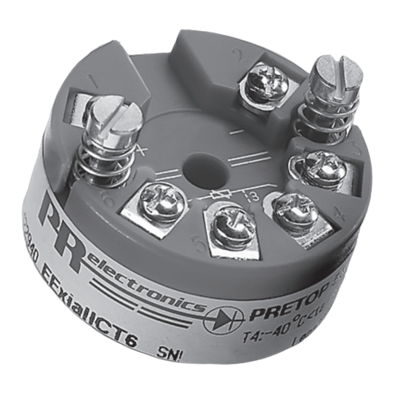
PR electronics 5331 Bedienungsanleitung
2-draht universal-messumformer
Vorschau ausblenden
Andere Handbücher für 5331:
- Bedienungsanleitung (24 Seiten) ,
- Bedienungsanleitung (29 Seiten) ,
- Bedienungsanleitung (69 Seiten)
Inhaltszusammenfassung für PR electronics 5331
- Seite 1 5 3 3 1 2 - D r a h t U n i v e r s a l - M e s s u m f o r m e r N r . 5 3 3 1 V 1 1 5 - D E A b S e r i e n n r .
-
Seite 3: Inhaltsverzeichnis
2-DRAHT UNIVERSALMESSUMFORMER 5331 Inhaltsverzeichnis Verwendung....................Technische Merkmale ................Montage / Installation ................Anwendungen ..................Bestellangaben: 5331 ................Elektrische Daten ................... Anschlüsse ....................Blockdiagramm ..................Programmierung ..................10 Abmessungen ..................11 Montage von Fühlerleitungen ............11 Appendix ....................12 ATEX Installation Drawing - 5331A ..........13 ATEX Installation Drawing - 5331D .......... -
Seite 4: Verwendung
• Die gespeicherten Daten werden laufend kontrolliert. Montage / Installation • Für DIN Form B Sensorkopf Montage. Im sicheren Bereich kann der 5331 auf einer DIN- Schiene mittels der PR-Armatur Typ 8421 montiert werden. 5331V 1 15 - D E... -
Seite 5: Anwendungen
ANWENDUNGEN 2-Draht-Installation WTH in 4...20 mA im Kontrollraum 2-Draht-Installation TE in 4...20 mA im Kontrollraum Widerstand 2-Draht-Installation in 4...20 mA im Kontrollraum 2-Draht-Installation mV in 4...20 mA im Kontrollraum 5 33 1 V 1 15 - DE... -
Seite 6: Bestellangaben: 5331
Bestellangaben: 5331 Umgebungs- Galvanische Version temperatur Trennung 5331 Standard -40°C...+85°C : 3 1500 VAC CSA, FM, ATEX, IECEx & INMETRO Elektrische Daten Spezifikationsbereich: -40°C bis +85°C Allgemeine Daten: Versorgungsspannung, DC Standard ............. 7,2...35 V CSA, FM, ATEX, IECEx & INMETRO ... 7,2...30 VDC Verlustleistung Standard ............. -
Seite 7: Eingangsart
Grundwerte Grund- Temperatur- Eingangsart Genauigkeit koeffizient ≤ ±0,2°C ≤ ±0,01°C/°C Lin. R ≤ ±0,1 Ω ≤ ±10 mΩ / °C ≤ ±10 µV ≤ ±1 µV / °C Volt TE-Typ: ≤ ±1°C ≤ ±0,05°C / °C E, J, K, L, N, T, U TE-Typ: B, R, S, ≤... - Seite 8 TE-Eingang: Min. Max. Min. Temperatur Temperatur Spanne Norm +400°C +1820°C 100°C IEC584 -100°C +1000°C 50°C IEC584 -100°C +1200°C 50°C IEC584 -180°C +1372°C 50°C IEC584 -100°C +900°C 50°C DIN 43710 -180°C +1300°C 50°C IEC584 -50°C +1760°C 100°C IEC584 -50°C +1760°C 100°C IEC584 -200°C +400°C...
- Seite 9 Zulassungen: EMV ................2014/30/EU CCOE ................P337392/1 RoHS ................2011/65/EU EAC ................TR-CU 020/2011 Marine-Zulassung: DNV-GL, Ships & Offshore ........Standard for Certification No. 2.4 Ex / I.S.: ATEX 2014/34/EU 5331A ..............KEMA 10ATEX0002 X 5331D..............KEMA 06ATEX0062 X FM-Zertifikat .............. FM17US0013X CSA-Zertifikat ............
-
Seite 10: Anschlüsse
ANSCHLÜSSE Eingang: WTH, 2-Leiter WTH, 3-Leiter WTH, 4-Leiter TE, interne CJC TE, externe CJC Widerst., 2-Leiter Widerst., 3-Leiter Widerst., 4-Leiter Ausgang: 2-Draht-Installation 5331V 1 15 - D E... -
Seite 11: Blockdiagramm
BLOCKDIAGRAMM 5 33 1 V 1 15 - DE... -
Seite 12: Programmierung
PROGRAMMIERUNG • Loop Link ist eine batteriegespeiste Schnittstelle zur Programmierung des 5331. • Bezüglich Programmierung verweisen wir auf die nachfolgende Zeichnung und die “Hilfe”-Funktion im PReset-Programm. • Loop Link darf nicht zur kommunikation mit Modulen, die in Ex-gefährdeten Bereichen installiert sind, benutz werden. -
Seite 13: Abmessungen
Abmessungen Montage von Fühlerleitungen ø 6 mm 20.2 m m 33 mm ø 44 mm Die Leitungen müssen zwischen den Metallplatten 5 33 1 V 1 15 - DE... -
Seite 14: Appendix
APPENDIX ATEX Installation Drawing - 5331A ATEX Installation Drawing - 5331D IECEx installation drawing - 5331A IECEx installation drawing - 5331D FM Installation Drawing - 5331D CSA Installation Drawing - 5331D INMETRO Instruções de Segurança - 5331A INMETRO Instruções de Segurança - 5331D 5331V 1 15 - D E... - Seite 15 5331QA02 LERBAKKEN 10, 8410 RØNDE DENMARK. WWW.PRELECTRONICS.COM ATEX Installationszeichnung Für die sichere Installation von 5331A3B oder 5334A3B ist Folgendes zu beachten: Das Gerät darf nur von qualifiziertem Personal eingebaut werden, das mit den nationalen und internationalen Gesetzen, Richtlinien und Standards auf diesem Gebiet vertraut ist. Das Baujahr kann aus den ersten beiden Ziffern der Seriennummer ersehen werden.
- Seite 16 5331QA01 LERBAKKEN 10, 8410 RØNDE DENMARK. WWW.PRELECTRONICS.COM ATEX Installationszeichnung Für die sichere Installation von 5331D oder 5334B ist Folgendes zu beachten: Das Gerät darf nur von qualifiziertem Personal eingebaut werden, das mit den nationalen und internationalen Gesetzen, Richtlinien und Standards auf diesem Gebiet vertraut ist. Das Baujahr kann aus den ersten beiden Ziffern der Seriennummer ersehen werden.
- Seite 17 5331QA01 LERBAKKEN 10, 8410 RØNDE DENMARK. WWW.PRELECTRONICS.COM Installationsvorschriften Die galvanische Trennung zwischen dem Sensorkreis und dem Eingangskreis ist nicht unfehlbar. Allerdings ist die galvanische Trennung zwischen den Kreisen so ausgelegt, dass diese eine Testspannung von 500 VAC für eine Minute aushält. Für Anwendung in einer potentiellen explosiven Atmosphäre - basierend auf entflammbares Gas - muss der Messumformer in einem Gehäuse, welcher einen Schutzgrad von mindestens IP20 gemäß...


