SICK DMD Betriebsanleitung
Entfernungs-messgerät

Verwandte Anleitungen für SICK DMD


Inhaltszusammenfassung für SICK DMD
- Seite 1 E n t f e r n u n g s - M e s s g e r ä t D i s t a n c e M e a s u r i n g D e v i c e D M D S S I / P r o f i b u s D P / I n t e r b u s - S...
-
Seite 2: Inhaltsverzeichnis
2.3 Geräteansicht..........................4 2.4 Handhabungshinweise ........................4 2.4.1 Bestimmungsgemäße Verwendung ................4 Inbetriebnahme ..........................5 3.1 DIP-Schalterstellungen ........................5 3.1.1 DIP-Schalterstellungen: ....................6 3.2 Austausch der alten Baureihe EDM gegen DMD: ...............8 3.3 Leuchtdiodenanzeige........................8 3.3.1 Funktionsanzeige ......................8 3.3.2 Diagnoseanzeige Profibus DP..................8 3.3.3 Diagnoseanzeige Interbus-S ...................9 3.3.4 Diagnoseanzeige SSI......................9... - Seite 3 Seite 3 7.3 Umlenkspiegel für DMD USP-DMD .....................20 7.4 Haltewinkel für DMD BEF-WN-DMD (im Lieferumfang enthalten) ...........20 Maßbild ............................21 Wartung ............................21...
-
Seite 4: Einführung
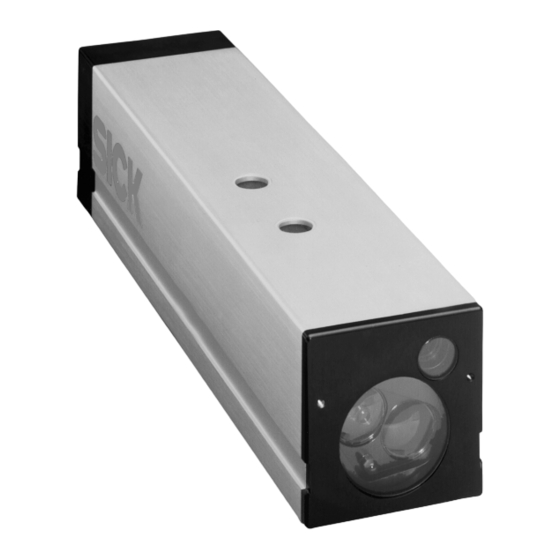
2 Einführung 2.1 Benutzerhinweis Das DMD ist ein kompakter optischer Distanzsensor. Es misst die Distanz zu einer Reflexfolie nach dem Prinzip der Pulslaufzeitmessung (Laufzeitmessung). Eine Reflexfolie befindet sich immer im Sichtfeld des Sensors und wird in der optischen Achse des Lichtstrahls bewegt. Typische Anwen- dungen sind das Positionieren von schienengebundenen Fahrzeugen wie Regalbediengeräte oder... -
Seite 5: Inbetriebnahme
Seite 5 3 Inbetriebnahme 3.1 DIP-Schalterstellungen Nach etwa 10 Sekunden der Initialisierung erlischt die rote Front-LED, sofern das DMD auf einen Reflektor ausgerichtet ist. Um die angegebene Genauigkeit zu erreichen, lassen Sie eine Aufwärmphase von etwa 30 Minuten zu. Anschließend ist das DMD messbereit. -
Seite 6: Dip-Schalterstellungen
Seite 6 Bemerkungen: Messwertalter: Zeit, an der ein neuer Messwert abhängig von der Messwertanzahl an der Schnittstelle anliegt Messwertanzahl: Anzahl der Messwerte, die zur Bildung des Mittelwertes herangezogen werden Umschaltung auf höhere Messwertanzahl erfolgt bei langsamer Zieländerung intern Modus 0: Position erreicht halt Fenster (PEH) in der Steuerung (typ. 3 mm - 5 mm, anlagenabhängig) Modus 2: Bei Zielstillstand wird der letzte gültige Messwert ausgegeben 3.1.1... - Seite 7 Seite 7 3.1.1.1 Modus 0 3.1.1.2 Modus 1 3.1.1.3 Modus 2 3.1.1.4 Modus 3 3.1.1.5 Modus 4 3.1.1.6 Modus 5 3.1.1.7 Modus 6 3.1.1.8 Modus 7...
-
Seite 8: Austausch Der Alten Baureihe Edm Gegen Dmd
Seite 8 3.2 Austausch der alten Baureihe EDM gegen DMD: ⇒ Modus 0 Modus 0 1 2 3 4 5 6 7 8 1 2 3 4 ⇒ Modus 3 Modus 1 1 2 3 4 1 2 3 4 5 6 7 8 ⇒... -
Seite 9: Diagnoseanzeige Interbus-S
Seite 9 3.3.3 Diagnoseanzeige Interbus-S Grüne LED außen leuchtet: Interbus erfolgreich initialisiert Grüne LED mittig leuchtet: Datentransfer auf Interbus findet statt Rote LED leuchtet: Interbus nicht vorhanden bzw. nicht initialisiert 3.3.4 Diagnoseanzeige SSI keine 3.3.5 Front-LED Die Front-LED leuchtet während der Initialisierung des Gerätes nach Einschalten der Versorgungs- spannung und erlischt nach etwa 10 Sekunden (sofern auf ein Ziel ausgerichtet). -
Seite 10: Installationshinweise
Seite 10 4 Installationshinweise 4.1 Schnittstellen und Anschlussbelegung 4.1.1 Anschlussbelegung der 14-poligen und der 4-poligen Schraubklemme 14-polige Schraubklemme (X2, X3) Profibus DP Interbus-S COM2 /DI2 /DO2 CLK - P (B) CLK + N (A) /DI1 DATA - DATA + /DO1 P (B) N (A) COM1... -
Seite 11: Beschreibung Der Ssi-Schnittstelle
Seite 11 Allgemeines Bei jeder Schnittstellenart muss zwischen der Gehäusemasse des DMD (Schraubklemme X5) und der Metallkonstruktion der Anlage eine hochfrequenztechnische (Schirmgeflecht) Verbindung hergestellt werden, um elektromagnetische Störungen zu unterdrücken. Die Verbindung soll so kurz als möglich ausgeführt werden. 4.1.2 Beschreibung der SSI-Schnittstelle Zwischen Data + und Data - muss am Steuerrechner ein 100Ω... -
Seite 12: Beschreibung Der Profibus Dp-Schnittstelle
Schalter S2 in die Schalterstellung 2 (Widerstandskombination abgeschaltet) zu bringen (Bild 5). Mit den zwei Drehschaltern in der Gehäuserückwand des DMD ist die Profibus-Slave-Adresse einzustellen (Bild 3). Es ist ein Standard Profibus-Kabel zu verwenden. Der Kabelschirm muss beidseitig aufgelegt werden. Im Steckerdeckel ist hierfür die Schraubklemme X5 zu verwenden. -
Seite 13: Ausrichthinweise
Seite 13 4.2 Ausrichthinweise Bei der Justage ist zu beachten, dass der Laserpointer seitlich versetzt zur Messoptik angebracht ist. Die Justage gilt für beide Reflektortypen (Folie und Linsenreflektor) und ist bei maximaler Messentfernung vorzunehmen. Richten Sie das Gerät in der Weise aus, dass sich der Mittelpunkt des Laserpointerfleckes horizontal 26 mm und vertikal 16 mm vom Mittelpunkt des Reflektors (Bild 6) befindet. -
Seite 14: Reflektoranordnung
Seite 14 4.3 Reflektoranordnung Linsenreflektor DMD-Seitenansicht Messstrahldurchmesser: ca. 5 cm ca. 10 cm ca. 30 cm ca. 70 cm DMD-Draufsicht DMD-Draufsicht Bild 7: Reflektoranordnungen 1... - Seite 15 Seite 15 Minimalanordnung bei Entfernungen > 120 m bis 240 m (2 x Linsenreflektor PL 140L) Bild 8: Reflektoranordnungen 2...
-
Seite 16: Reflexionsfolien
4.4 Reflexionsfolien Die Reflektorgröße ist so zu wählen, das der Lichtfleck bei Erschütterungen nicht von dem Reflektor abwandert. Wird das DMD zum Beispiel um 1 Grad verdreht, wandert der Lichtfleck in 130 m Abstand um ca. 2 m aus. 4.4.1 Diamond Grade Konfektionierbar, max. -
Seite 17: Hilfestellung Im Fehlerfall
Seite 17 5 Hilfestellung im Fehlerfall Fehlererscheinung mögliche Ursache Abhilfe Rote LED im Frontfenster Messziel nicht erfasst Ausrichtung überprüfen leuchtet länger als 10 sek. Reflektor oder Gerätescheibe verschmutzt Messbereichsüberschreitung Rote Kontroll-LED Messziel nicht erfasst Ausrichtung überprüfen leuchtet Reflektor oder Gerätescheibe verschmutzt Rote &... -
Seite 18: Technische Daten
Seite 18 6 Technische Daten Technische Daten 120- 120- 120- 240- 240- 240- 1111 2111 3111 1111 2111 3111 1111 2111 3111 Schnittstellen SSI: GRAY/BINÄR Profibus-DP, 4 byte inkl. Errorbit Interbus-S, 4 byte inkl. Errorbit Messbereich 0,5 m ... 50 m 0,5 m ... -
Seite 19: Zubehör
Seite 19 7 Zubehör 7.1 Linsenreflektor PL 140L Bestellnummer: 5 308 918 7.2 Haltewinkel für Linsenreflektor BEF-PL 140L Bestellnummer: 5 308 917... -
Seite 20: Umlenkspiegel Für Dmd Usp-Dmd
Seite 20 7.3 Umlenkspiegel für DMD USP-DMD Bestellnummer: 5 308 919 7.4 Haltewinkel für DMD BEF-WN-DMD (im Lieferumfang enthalten) Bestellnummer: 5 308 915... -
Seite 21: Maßbild
Seite 21 8 Maßbild Bild 9: Geräteabmessungen 9 Wartung SICK-Sensoren sind wartungsfrei. Wir empfehlen, in regelmäßigen Abständen die optischen Grenzflächen zu reinigen, Verschraubungen und Steckverbindungen zu überprüfen...