Werbung
Quicklinks
FRANÇAIS
Module Radioline pour la communication bidirectionnelle
Respecter ces instructions pour une utilisation sûre et correcte de l'appareil. Conserver ces instructions
pour pouvoir les consulter ultérieurement. Prendre aussi impérativement en compte la documentation
complémentaire disponible à l'adresse phoenixcontact.net/products.
1 Consignes de sécurité
1.1 Instructions d'installation
• L'utilisation du système radio n'est autorisée qu'avec les accessoires disponibles auprès de Phoenix Contact.
L'emploi d'autres accessoires peut entraîner l'annulation de l'autorisation d'exploitation.
• Les accessoires admis pour ce système radio sont mentionnés avec le produit, à l'adresse
phoenixcontact.net/products.
• Phoenix Contact déclare que le système de transmission radio ci-joint est conforme aux exigences fonda-
mentales et aux autres prescriptions pertinentes de la directive 2014/53/UE.
• L'appareil de catégorie 3 est conçu pour être installé dans des atmosphères explosibles de zone 2. L'appareil
est conforme aux exigences des normes suivantes :
– EN/CEI 60079-0, EN/CEI 60079-7, EN/CEI 60079-15. Pour plus de détails, se reporter à la déclaration de
conformité UE jointe et également disponible sur notre site Web dans sa version la plus récente.
• L'installation, l'utilisation et la maintenance doivent être confiées à un personnel spécialisé dûment qualifié en
électrotechnique. Respecter les instructions d'installation.
• Lors de la mise en place et de l'utilisation, respecter les dispositions et les normes de sécurité en vigueur, les
normes de sécurité nationales et les règles générales relatives à la technique. Les caractéristiques tech-
niques de sécurité se trouvent dans ce document.
• Respecter les conditions définies pour une utilisation en atmosphère explosible. Respecter également les exi-
gences de la norme EN 60079-14.
• L'ouverture ou la transformation de l'appareil ne sont pas admissibles. Ne procédez à aucune réparation sur
l'appareil, mais remplacez-le par un appareil équivalent. Seul le fabricant est autorisé à effectuer des répara-
tions sur l'appareil. Le fabricant n'est pas responsable des dommages résultant d'infractions à cette règle.
• Ne soumettez jamais le produit à des sollicitations mécaniques et/ou thermiques dépassant les limites indi-
quées.
• L'appareil est conforme aux règlements relatifs aux parasites (CEM) destinés au domaine industriel (catégo-
rie de protection A). L'utilisation dans une zone d'habitation peut créer des parasites.
• Seuls les appareils Phoenix Contact spécifiés doivent être raccordés à l'interface à 12 pôles S-PORT.
1.2 Installation en zone 2
• L'utilisation en atmosphères explosibles est interdite en Chine.
• Mettez l'appareil en place de manière à ce que l'indice de protection minimum atteint soit IP54, conformément
à EN 60529. Utilisez pour cela un boîtier adapté et homologué, qui répond aux exigences de la norme
EN 60079-7.
• Seuls les appareils destinés à être utilisés dans la zone Ex 2 et conçus pour être utilisés dans les conditions
régnant sur le lieu d'installation peuvent être raccordés à des circuits électriques situés en zone 2.
• L'encliquetage sur le connecteur de bus sur rail DIN et le déverrouillage ou le branchement et débranchement
des câbles et des connexions dans des zones explosibles sont autorisés uniquement en l'absence de ten-
sion.
• L'utilisation de l'interface de programmation est autorisée uniquement si l'absence d'atmosphère explosible
est garantie.
• Les connexions verrouillables doivent disposer d'un verrou opérationnel (par ex. un crochet, un raccordement
vissé, etc.) pour garantir leur fonctionnement en toute sécurité. Mettre le verrou en place. Réparer immédia-
tement les connecteurs endommagés.
• Utilisez l'appareil dans la zone Ex 2 uniquement si tous les connecteurs mâles sont complètement enfichés.
• Raccorder un seul conducteur par borne.
• Utilisez l'appareil dans un environnement qui présente un degré de pollution maximum de 2 selon EN/
CEI 60664-1.
• Les commutateurs accessibles de l'appareil ne doivent être actionnés que lorsque l'appareil n'est pas sous
tension.
• L'appareil doit être mis hors service et retiré immédiatement de la zone Ex s'il est endommagé ou s'il a été
soumis à des charges ou stocké de façon non conforme, ou s'il présente un dysfonctionnement.
• Veiller à ce que l'énergie radio émise ne soit focalisée ni par l'antenne elle-même, ni par les équipements ins-
tallés à proximité de l'antenne et qu'elle ne puisse pénétrer dans les zones 1 ou 0 avoisinantes. La puissance
d'émission est mentionnée dans les caractéristiques techniques.
• Le câble HF conduisant à l'antenne doit être adapté aux conditions environnementales. Installer le câble de
manière à ce qu'il ne soit pas soumis à des détériorations mécaniques, la corrosion, des influences chimiques
et des détériorations provoquées par la chaleur ou les rayonnements UV. Il en va de même pour l'antenne
raccordée au câble et faisant office de terminaison de celle-ci.
• L'antenne elle-même doit répondre aux exigences de la norme EN 60079-0 concernant les boîtiers et les
charges électrostatiques. Si ce n'est pas le cas, monter l'antenne dans un boîtier répondant aux exigences de
normes EN 60079-0 et EN 60079-15 et dont l'indice de protection est supérieur ou égal à IP54 (EN 60529).
• Le produit n'est pas conçu pour une utilisation en atmosphères à risque d'explosion de poussières.
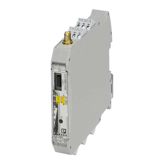
2 Description ( - )
Emetteur-récepteur radio 868 MHz à interface RS-232/RS-485, extensible avec modules d'extension d'E/S. Il est
utilisable au choix comme station de base, à distance ou répéteur. Destiné aux réseaux radio (point à point,
étoile, maille) pouvant compter jusqu'à 99 équipements.
2.1 Instructions de raccordement
AVERTISSEMENT : Risque dû à la tension électrique
Certains composants de l'appareil peuvent être soumis à des tensions électriques dangereuses au cours
du fonctionnement. Le non-respect des avertissements peut provoquer de graves blessures et/ou dom-
mages matériels.
– À proximité de l'appareil, prévoyez un commutateur/disjoncteur identifié comme étant le dispositif de
déconnexion de cet appareil ou de l'ensemble de l'armoire électrique.
– Prévoyez un dispositif de protection contre les surintensités (I ≤ 6 A) dans l'installation.
– En cas de travaux de maintenance et lors de la configuration, veuillez débrancher l'appareil de toutes
les sources d'alimentation (l'appareil peut rester branché avec des circuits électriques SELV ou PELV).
– Grâce à son boîtier, l'appareil dispose d'une isolation de base vis-à-vis des appareils adjacents pour
300 V eff. Il convient de prendre ce point en compte lors de l'installation de plusieurs appareils en jux-
taposition et, le cas échéant, d'installer une isolation supplémentaire. Si l'appareil juxtaposé dispose
d'une isolation de base, aucune isolation supplémentaire n'est requise.
IMPORTANT : décharge électrostatique
Une décharge électrostatique peut endommager, voire détruire des composants.
– Lors de la manipulation de l'appareil, il est impératif de respecter les mesures de sécurité nécessaires
en matière de décharges électrostatiques (ESD), conformément à EN 61340-5-1 et CEI 61340-5-1.
Bornes à vis enfichables
2
RSSI
Sortie de contrôle pour analyser l'intensité du signal radio (0...3 V DC)
3
+24 V/0 V
Alimentation de l'appareil
10
D(A) / D(B)
Interface V.24 (RS-485)
11
RX / TX / GND
Interface RS-232
12
Liaison RF
Sortie de relais avec contact inverseur (indépendant du potentiel)
Éléments de commande
1
Raccordement SMA de l'antenne (connecteur femelle)
4
PORT S
Interface de programmation 12 pôles
RAD-ID
Sélecteur d'adresse via molette
5
6
Bouton SET
7
Raccordement pour connecteur sur profilé
9
Pied métallique de verrouillage, fixation sur profilé normé
13..17
Voyants de diagnostic et d'état
2.2 Installation ( + )
Le produit est encliquetable sur tous les rails DIN de 35 mm conformes à la norme EN/CEI 60715. Le connecteur
de bus sur rail DIN ME17,5 TBUS 1,5/5-ST-3,81 GN ponte la tension d'alimentation et assiste la communication
avec jusqu'à 32 module d'extension E/S différents.
Pour utiliser le connecteur sur profilé, insérez-le d'abord dans le profilé. ()
ENGLISH
Radioline wireless module for bidirectional communication
For safe and proper use, follow these instructions. Keep them for future reference.
Please also refer to the additional documentation at phoenixcontact.net/products.
1 Safety notes
1.1 Installation notes
• Operation of the wireless system is only permitted when using accessories available from Phoenix Con-
tact. The use of any other components can lead to the withdrawal of the operating license.
• You will find the approved accessories for this wireless system listed with the product at phoenixcon-
tact.net/products.
• Phoenix Contact hereby declares that this wireless system complies with the basic requirements and
other relevant regulations specified in Directive 2014/53/EU.
• The category 3 device is designed for installation in zone 2 potentially explosive areas. The device sat-
isfies the requirements of the following standards:
– EN/IEC 60079-0, EN/IEC 60079-7, EN/IEC 60079-15. Comprehensive details are to be found in the EU
Declaration of Conformity which is enclosed and also available on our website in the latest version.
• Installation, operation, and maintenance may only be carried out by qualified electricians. Follow the in-
stallation instructions as described.
• When installing and operating the device, the applicable regulations and safety directives (including na-
tional safety directives), as well as general technical regulations, must be observed. The safety-relevant
data is listed in this document.
• Observe the specified conditions for use in potentially explosive areas! Also observe the requirements
of EN 60079-14.
• The device must not be opened or modified. Do not repair the device yourself, replace it with an equiv-
alent device. Repairs may only be carried out by the manufacturer. The manufacturer is not liable for
damage resulting from violation.
• Do not subject the product to mechanical and/or thermal stress that exceeds the specified limits.
• The device complies with the EMC regulations for industrial areas (EMC class A). When using the de-
vice in residential areas, it may cause radio interference.
• Only specified devices from Phoenix Contact may be connected to the 12-pos. S-PORT interface.
1.2 Installation in Zone 2
• Use in potentially explosive areas is not permitted in China.
• The device should be installed so that at least IP54 degree of protection is achieved in accordance with
EN 60529. To this end, a suitable, approved housing that meets the requirements of EN 60079-7 should
be used.
• Only devices that are designed for operation in Ex Zone 2 and the conditions at the installation location
may be connected to the circuits in Zone 2.
• In potentially explosive areas, only snap the device onto or off of the DIN rail connector and connect and
disconnect cables and connectors when the power is disconnected.
• The programming interface may only be used if it has been ensured that there is no potentially explosive
atmosphere present.
• For safe operation, lockable plug connections must have a functional interlock (e. g. locking clip, screw
connection etc.). Insert the interlock. Repair any damaged connectors immediately.
• Only operate the device in Ex zone 2 when all plugs are fully inserted.
• Only connect one cable per terminal point.
• Use the device in an environment that does not exceed pollution degree 2 in accordance with EN/
IEC 60664-1.
• The switches of the device that can be accessed may only be actuated when the power supply to the
device is disconnected.
• The device must be stopped and immediately removed from the Ex area if it is damaged, was subject
to an impermissible load, stored incorrectly or if it malfunctions.
• Ensure that the radiated wireless power is neither bundled (focused) by the antenna itself nor by any
inserts in the environment of the antenna, and that it cannot enter neighboring zones 1 or 0. For the
transmission power, please refer to the technical data.
• The HF cable to the antenna must be suitable for the ambient conditions. Install the cable such that it is
protected against mechanical damage, corrosion, chemical stress, and negative effects from heat or
UV radiation. The same applies to the antenna which is connected to the cable and which functions as
a cable termination.
• The antenna must meet the requirements of EN 60079-0 with regard to housing and electrostatic dis-
charge. Otherwise install the antenna in housing that meets the requirements of EN 60079-0 and
EN 60079-15 and has at least IP54 protection (EN 60529).
• The product is not designed for use in potentially dust-explosive atmospheres.
2 Description ( - )
868 MHz wireless transceiver with RS-232/RS-485 interface, can be extended with I/O extension modules.
Can be used as a base, remote, or repeater station. For wireless networks (point-to-point, star, mesh) with
up to 99 devices.
2.1 Connection notes
WARNING: Risk of electric shock
During operation, certain parts of this device may carry hazardous voltages. Disregarding this warn-
ing may result in damage to equipment and/or serious personal injury.
– Provide a switch/circuit breaker close to the device, which is labeled as the disconnect device for
this device or the entire control cabinet.
– Provide overcurrent protection (I ≤ 6 A) in the installation.
– Disconnect the device from all power sources during maintenance work and configuration (the
device can remain connected to SELV or PELV circuits).
– The housing of the device provides a basic insulation against the neighboring devices, for
300 V eff. If several devices are installed next to each other, this has to be taken into account,
and additional insulation has to be installed if necessary. If the neighboring device is equipped
with basic insulation, no additional insulation is necessary.
NOTE: electrostatic discharge!
Electrostatic discharge can damage or destroy components.
– When handling the device, observe the necessary safety precautions against electrostatic dis-
charge (ESD) in accordance with EN 61340-5-1 and IEC 61340-5-1.
Plug-in screw terminal blocks
2
RSSI
Test output for evaluation of the wireless signal strength (0...3 V DC)
3
+24 V/0 V
Device supply
10
D(A) / D(B)
RS-485 interface
11
RX / TX / GND
RS-232 interface
12
RF Link
Relay output with changeover contact (floating)
Operating elements
1
RSMA antenna connection (socket)
S-PORT
12-pos. programming interface
4
5
RAD-ID
Address setting via thumbwheel
6
SET button
7
Connection for DIN rail connector
9
Metal foot catch for DIN rail fixing
13..17
Diagnostic and status indicators
2.2 Installation ( + )
The product can be snapped onto all 35 mm DIN rails in accordance with EN/IEC 60715. The
ME17,5 TBUS 1,5/5-ST-3,81 GN DIN rail connector bridges the supply voltage and supports communica-
tion with up to 32 different I/O extension modules. When using the DIN rail connector, first place it into the
DIN rail. ()
DEUTSCH
Radioline-Funkmodul für bidirektionale Kommunikation
Befolgen Sie diese Anweisungen für einen sicheren und ordnungsgemäßen Gebrauch. Bewahren Sie die
Anweisungen zum späteren Nachschlagen auf.
Beachten Sie unbedingt auch die weiterführende Dokumentation unter phoenixcontact.net/products.
1 Sicherheitshinweise
1.1 Errichtungshinweise
• Der Betrieb des Funksystems ist nur unter Verwendung des bei Phoenix Contact erhältlichen Zubehörs zu-
lässig. Der Einsatz von anderen Zubehörkomponenten kann zum Erlöschen der Betriebsgenehmigung füh-
ren.
• Das zugelassene Zubehör für dieses Funksystem finden Sie am Produkt unter phoenixcontact.net/products.
• Hiermit erklärt Phoenix Contact, dass sich das vorliegende Funksystem in Übereinstimmung mit den grund-
legenden Anforderungen und den anderen relevanten Vorschriften der Richtlinie 2014/53/EU befindet.
• Das Gerät der Kategorie 3 ist zur Installation im explosionsgefährdeten Bereich der Zone 2 geeignet. Das Ge-
rät erfüllt die Anforderungen der folgenden Normen:
– EN/IEC 60079-0, EN/IEC 60079-7, EN/IEC 60079-15. Genaue Angaben sind der EU-Konformitätserklärung
zu entnehmen, die beiliegt und auf unserer Webseite in der aktuellen Version zu finden ist.
• Die Installation, Bedienung und Wartung ist von elektrotechnisch qualifiziertem Fachpersonal durchzuführen.
Befolgen Sie die beschriebenen Installationsanweisungen.
• Halten Sie die für das Errichten und Betreiben geltenden Bestimmungen und Sicherheitsvorschriften (auch
nationale Sicherheitsvorschriften) sowie die allgemeinen Regeln der Technik ein. Die sicherheitstechnischen
Daten sind diesem Dokument zu entnehmen.
• Halten Sie die festgelegten Bedingungen für den Einsatz in explosionsgefährdeten Bereichen ein! Beachten
Sie auch die Anforderungen der EN 60079-14.
• Öffnen oder Verändern des Geräts ist nicht zulässig. Reparieren Sie das Gerät nicht selbst, sondern ersetzen
Sie es durch ein gleichwertiges Gerät. Reparaturen dürfen nur vom Hersteller vorgenommen werden. Der
Hersteller haftet nicht für Schäden aus Zuwiderhandlung.
• Setzen Sie das Produkt keiner mechanischen und/oder thermischen Beanspruchung aus, die die beschrie-
benen Grenzen überschreitet.
• Das Gerät erfüllt die Funkschutzbestimmungen (EMV) für den industriellen Bereich (Funkschutzklasse A).
Beim Einsatz im Wohnbereich kann es Funkstörungen verursachen.
• An die 12-polige S-PORT-Schnittstelle dürfen nur Geräte von Phoenix Contact angeschlossen werden, die
hierfür spezifiziert sind.
1.2 Installation in der Zone 2
• Der Einsatz in explosionsgefährdeten Bereichen ist in China nicht erlaubt.
• Das Gerät ist so zu errichten, dass eine Schutzart von mindestens IP54 gemäß EN 60529 erreicht wird. Hier-
zu ist ein geeignetes, zugelassenes Gehäuse zu verwenden, das den Anforderungen der EN 60079-7 ent-
spricht.
• An Stromkreise in der Zone 2 dürfen nur Geräte angeschlossen werden, die für den Betrieb in der Ex-Zone 2
und die am Einsatzort vorliegenden Bedingungen geeignet sind.
• Das Auf- und Abrasten auf den Tragschienen-Busverbinder bzw. das Anschließen und das Trennen von Lei-
tungen und Steckerverbindungen im explosionsgefährdeten Bereich sind nur im spannungslosen Zustand
zulässig.
• Die Programmierschnittstelle darf nur verwendet werden, wenn sichergestellt ist, dass keine explosionsfähi-
ge Atmosphäre vorhanden ist.
• Für den sicheren Betrieb müssen verriegelbare Steckverbindungen eine funktionsfähige Verriegelung (z. B.
Rasthaken, Verschraubung etc.) aufweisen. Setzen Sie die Verriegelung ein. Setzen Sie beschädigte Ste-
cker unverzüglich instand.
• Betreiben Sie das Gerät in der Ex-Zone 2 nur, wenn alle Stecker vollständig eingesteckt sind.
• Schließen Sie nur eine Leitung pro Klemmpunkt an.
• Verwenden Sie das Gerät in einer Umgebung, die höchstens den Verschmutzungsgrad 2 gemäß EN/
IEC 60664-1 aufweist.
• Die zugänglichen Schalter des Geräts dürfen nur betätigt werden, wenn das Gerät stromlos ist.
• Das Gerät ist außer Betrieb zu nehmen und unverzüglich aus dem Ex-Bereich zu entfernen, wenn es beschä-
digt ist, unsachgemäß belastet oder gelagert wurde bzw. Fehlfunktionen aufweist.
• Stellen Sie sicher, dass die abgestrahlte Funkenergie weder durch die Antenne selbst noch durch Einbauten
in der Umgebung der Antenne gebündelt (fokussiert) werden und in benachbarte Zonen 1 oder 0 eindringen
kann. Die Sendeleistung entnehmen Sie den technischen Daten.
• Die HF-Leitung zur Antenne muss für die Umgebungsbedingungen geeignet sein. Installieren Sie diese der-
art, dass sie gegen mechanische Beschädigung, Korrosion, chemische Einwirkungen und Beeinträchtigun-
gen durch Wärme bzw. UV-Strahlung geschützt ist. Das gleiche gilt für die an die Leitung angeschlossene
Antenne als Abschluss der Leitung.
• Die Antenne selbst muss die Anforderungen der EN 60079-0 erfüllen in Bezug auf Gehäuse und elektrosta-
tische Aufladung. Anderenfalls installieren Sie die Antenne in ein Gehäuse, das die Anforderungen der
EN 60079-0 und EN 60079-15 und mindestens die Schutzart IP54 (EN 60529) erfüllt.
• Das Produkt ist nicht für den Einsatz in staubexplosionsgefährdeten Atmosphären ausgelegt.
2 Beschreibung ( - )
868-MHz-Funktransceiver mit RS-232/RS-485-Schnittstelle, erweiterbar mit I/O-Erweiterungsmodulen. Einsetz-
bar wahlweise als Base-, Remote- oder Repeater-Station. Für Funknetzwerke (Punkt-zu-Punkt, Stern, Mesh) mit
bis zu 99 Teilnehmern.
2.1 Anschlusshinweise
WARNUNG: Gefahr durch elektrische Spannung!
Beim Betrieb können bestimmte Teile des Geräts unter gefährlicher Spannung stehen! Durch Nichtbeach-
tung der Warnhinweise können schwere Körperverletzungen und/oder Sachschäden entstehen!
– Sehen Sie in der Nähe des Geräts einen Schalter/Leistungsschalter vor, der als Trennvorrichtung für
dieses Gerät oder den gesamten Schaltschrank gekennzeichnet ist.
– Sehen Sie eine Überstromschutzeinrichtung (I ≤ 6 A) in der Installation vor.
– Trennen Sie das Gerät bei Instandhaltungsarbeiten und bei der Konfiguration von allen Energiequellen
(mit SELV- oder PELV-Stromkreisen kann das Gerät verbunden bleiben).
– Das Gerät besitzt durch sein Gehäuse eine Basisisolierung zu benachbarten Geräten für 300 V eff. Bei
der Installation mehrerer Geräte nebeneinander ist dieses zu beachten und ggf. eine zusätzliche Iso-
lierung zu installieren. Wenn das benachbarte Gerät eine Basisisolierung besitzt, ist keine zusätzliche
Isolierung erforderlich.
ACHTUNG: Elektrostatische Entladung!
Elektrostatische Entladung kann Bauelemente beschädigen oder zerstören.
– Beachten Sie beim Umgang mit dem Gerät die notwendigen Sicherheitsmaßnahmen gegen elektro-
statische Entladung (ESD) nach EN 61340-5-1 und IEC 61340-5-1.
Steckbare Schraubklemmen
2
RSSI
Prüfausgang zur Bewertung der Funksignalstärke (0...3 V DC)
3
+24V / 0V
Geräteversorgung
10
D(A) / D(B)
RS-485-Schnittstelle
11
RX / TX / GND
RS-232-Schnittstelle
12
RF-Link
Relaisausgang mit Wechslerkontakt (potenzialfrei)
Bedienelemente
1
RSMA-Antennenanschluss (Buchse)
4
S-PORT
12-polige Programmierschnittstelle
5
RAD-ID
Adresseinstellung via Rändelrad
6
SET-Taster
7
Anschluss für Tragschienen-Busverbinder
9
Metallfußriegel zur Normschienenbefestigung
13..17
Diagnose- und Statusanzeigen
2.2 Installation ( + )
Das Produkt ist auf alle 35-mm-Tragschienen nach EN/IEC 60715 aufrastbar. Der Tragschienen-Busverbinder
ME17,5 TBUS 1,5/5-ST-3,81 GN brückt die Versorgungsspannung und unterstützt die Kommunikation mit bis
zu 32 unterschiedlichen I/O-Erweiterungsmodulen.
Bei Einsatz des Tragschienen-Busverbinders legen Sie diesen zuerst in die Tragschiene ein. ()
Phoenix Contact GmbH & Co. KG
Flachsmarktstraße 8, 32825 Blomberg, Germany
Fax +49-(0)5235-341200, Phone +49-(0)5235-300
phoenixcontact.com
MNR 9064201
DE
Einbauanweisung für die Elektrofachkraft
EN
Installation notes for electrically skilled persons
FR
Instructions d'installation pour l'électricien qualifié
RAD-868-IFS
3
2
1
7
8
4
9
+2
4V
RS
SI +
0V
RS
SI -
AN
T
17
5
16
PW
R
8
6
DA
T
8
ER
R
15
14
RX
13
TX
D(
A)
D(
RX
B)
CO
TX
12
M
1
NO
GN
1
NC
D
1
11
10
AWG 24-14
2
0,2-2,5 mm
A
7 mm
B
0,5-0,6 Nm
5-7 lb In
RAD-ID
D(A)
RS485
4.1
D(B)
RF
4.2
RSSI+
RX
2.1
U
RS232
5.1
RSSI-
μC
TX
2.2
5.2
GND
5.3
+24 V
COM
1
1.1
6.1
DC
NO
0 V
1
1.2
6.2
DC
NC
1
6.3
IFS
IFS
A
B
C
D
E
© Phoenix Contact 2022
PNR 105760 - 05
DNR 83148888 - 05
2022-10-24
2904909
Werbung

Verwandte Anleitungen für Phoenix Contact RAD-868-IFS


Inhaltszusammenfassung für Phoenix Contact RAD-868-IFS
- Seite 1 • L'utilisation du système radio n'est autorisée qu'avec les accessoires disponibles auprès de Phoenix Contact. • Der Betrieb des Funksystems ist nur unter Verwendung des bei Phoenix Contact erhältlichen Zubehörs zu- tact. The use of any other components can lead to the withdrawal of the operating license.
-
Seite 2: Caractéristiques Techniques
Beachten Sie die besonderen Installationshinweise in der Dokumentation! IECEx IECEx IECEx Ex ec nC IIC T4 Gc (IECEx IBE 13.0019X) Vous trouverez la documentation complémentaire sous : For further documentation, go to: Weitere Dokumentation finden Sie unter: http://www.phoenixcontact.net/product/2904909 © Phoenix Contact 2022 PNR 105760 - 05 DNR 83148888 - 05... - Seite 3 • Por la presente, Phoenix Contact declara que el presente sistema inalámbrico cumple con los requisitos • Por meio desta, a Phoenix Contact declara que o presente sistema sem fio está em conformidade com os sposizioni rilevanti della direttiva 2014/53/UE.
- Seite 4 IECEx IECEx IECEx Ex ec nC IIC T4 Gc (IECEx IBE 13.0019X) © Phoenix Contact 2022 PNR 105760 - 05 DNR 83148888 - 05 Estão disponíveis outros documentos em: Encontrará más documentación en: Per l'ulteriore documentazione:...
- Seite 5 • Компания Phoenix Contact настоящим заявляет, что данная система радиосвязи отвечает всем основопо- • Phoenix Contact deklaruje, że niniejszy system radiowy jest zgodny z zasadniczymi wymogami i innymi • Phoenix Contact, işbu vesile ile, bu kablosuz sistemin 2014/53/EU sayılı Direktif dahilinde belirtilen лагающим требованиям и предписаниям Директивы 2014/53/ЕС.
- Seite 6 Lütfen dokümanda verilen özel montaj talimatlarına dikkat ediniz! IECEx IECEx IECEx Ex ec nC IIC T4 Gc (IECEx IBE 13.0019X) © Phoenix Contact 2022 PNR 105760 - 05 DNR 83148888 - 05 Dalsza dokumentacja dostępna jest pod adresem: Дополнительная документация находится здесь: Daha fazla dokümantasyona şuradan ulaşabilirsiniz:...