Inhaltsverzeichnis
Werbung
Quicklinks
Werbung
Kapitel
Inhaltsverzeichnis

Verwandte Anleitungen für bürkert 8323


Inhaltszusammenfassung für bürkert 8323
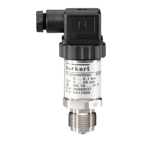
- Seite 1 Einbau- und Bedienungs-Hinweis für Typen 8323 und 8324 Installation and operating Instructions for Type 8323 and 8324 Montage et recommandation d’utilisation pour les types 8323 et Ex-8324 © 1999 Bürkert Werke GmbH & Co. Alle Rechte vorbehalten. All rights reserved. Tous droits réservés.
-
Seite 2: Inhaltsverzeichnis
Einbau- und Bedienungs-Hinweis für Typen 8323 und 8324 Inhalt 0.0 Allgemeines 0.1 Typen mit piezoresistivem Sensorelement 0.2 Typen mit Dünnfilm-Sensorelement 1.0 Service- und Wartungsarbeiten 2.0 Anbau und Inbetriebnahme 3.0 Elektrischer Anschluß 3.1 Stromausgang, Zweileiter 4.0 Abmessungen Gehäuse Typ 8323 Gehäuse Typ 8324 Druckanschlüsse und Einschraublöcher... -
Seite 3: Allgemeines
0.0 Allgemeines Die in der Bedienungsanleitung beschriebenen Bürkert- Druckmeßumformer wurden nach neuesten Erkenntnissen entwickelt, konstruiert und gefertigt. Alle Komponenten werden während der Fertigung strengen Qualitätskontrol- len und das fertige Gerät vor der Auslieferung einem Endtest unterzogen. Sie können also sicher sein, ein einwandfreies Produkt zu erhalten, das alle angegebenen Spezifikationen einhält oder übertrifft. -
Seite 4: Typen Mit Piezoresistivem Sensorelement
Silikonkautschuk vergossen. Alle meßstoffberührten Teile und die umhüllenden Bauteile sind aus CrNi-Stahl. 0.2 Typen mit Dünnfilm-Sensorelement Die Typen 8323 und 8324 mit Meßbereich 25 bar haben als Sensor eine Topf-Membrane, deren mediumabgewandte Seite in einem speziellen Verfahren (Sputtern) mit Wider- stands-Netzwerken beschichtet ist. -
Seite 5: Service- Und Wartungsarbeiten
1.0 Service- und Wartungsarbeiten Die hier beschriebenen Druckmeßumformer sind wartungs- frei! Sie enthalten keinerlei Komponenten, die vor Ort instandgesetzt oder ausgetauscht werden können. Reparaturen können ausschließlich im Werk durchgeführt werden. Je nach Einsatzbedingungen sollten die Druckmeßumfor- mer ca. 1 mal pro Jahr auf Einhaltung ihrer Spezifikationen überprüft und ggf. -
Seite 6: Anbau Und Inbetriebnahme
- Schraubring für Befestigung des Steckers entfernen - Nullpunkt am oberen Potentiometer einstellen - Spanne am unteren Potentiometer einstellen - Beide Einstellungen nochmals überprüfen - Schraubring wieder montieren Das Nullpunkt-Potentiometer steht oben, das Spannen- Potentiometer steht unten auf der Leiterplatte. Nullpunkt Spanne Schlauch... -
Seite 7: Elektrischer Anschluß
Sicherheitshinweise Beachten Sie unbedingt bei Montage, Inbetriebnahme und Betrieb dieser Druckmeßumformer die entsprechenden na- tionalen Sicherheitsvorschriften (z. B.:VDE 0100). Bei Nichtbeachten der entsprechenden Vorschriften kön- nen schwere Körperverletzungen und/oder Sachschäden auftreten. Nur entsprechend qualifiziertes Personal sollte an diesem Gerät arbeiten. 3.0 Elektrischer Anschluß... -
Seite 8: Stromausgang, Zweileiter
3.1 Stromausgang, Zweileiter Ausgangssignal 4 ... 20 mA Hilfsenergie = DC 10 ... 30 V Zulässige Bürde [Ohm] = (U [V] - 10 V) / 0,02 A Anschlußbelegung siehe Prinzipskizzen Elektrischer Anschluss +/S+ Hilfsenergie (DC) 4 ... 20 mA 0V/S-... - Seite 9 3.1 2-wire system The principal characteristic of the 2- +/S+ wire-system is the order of all measuring circuit components as a series connection. Plus power supply 0V/S- for the supply of the pressure transmitter and the 4 ... 20 mA output signal are carried by a common 0...20 mA connecting line.
- Seite 10 Installation and operating Instructions for Type 8323 and 8324 Contents 0.0 General 0.1 Types with piezoresistive sensor elements 0.2 Types with thin film sensor elements 1.0 Service and maintenance 2.0 Installation and commissioning 3.0 Wiring 3.1 mA signal, 2-wire 4.0 Dimensions...
-
Seite 11: General
0.0 General The Burkert pressure transmitter described in the operating instructions have been developed, designed and produced according to latest knowledge. All components are subjected to stringent quality controls during production and the finished instrument has undergone a final test before delivery. -
Seite 12: Types With Piezoresistive Sensor Elements
0.2 Types with thin film sensor element Types 8323 and 8324 with measuring range of 25 bar have a pot diaphragm as sensor, whose side away from the medium is coated by a special process (sputtering) with resistant networks. -
Seite 13: Service And Maintenance
1.0 Service and maintenance The Burkert pressure transmitters described here require no maintenance or servicing. They incorporate no components which can be repaired or replaced on the site. Repairs can only be carried out at the factory. Depending upon working conditions the pressure transmitters should be checked about once a year to ensure that they are within their specification and be adjusted if necessary. -
Seite 14: Installation And Commissioning
- Remove the screw ring for fastening the plug - Set zero point with above potentiometer - Set span point with below potentiometer - Check both settings once again - Refit screw ring The zero-potentiometer is sited above, the span- potentiometer below on the printed circuit board. -
Seite 15: Wiring
Safety instructions The appropriate national safety regulations (i. e. VDE 0100) must be observed when mounting, starting up and operating these pressure transmitters. In case of transmitters with classification explosive athmosphere observe also the details given on the conformity certificate as well as the respective specifications for explosion hazard use of the country concerned (e. -
Seite 16: Power Supply
3.1 Output signal, 2-wire Signal outpput 4 ... 20 mA Power supply = DC 10 ... 30 V Maximum load [Ohm] = (U [V] - 10 V) / 0,02 A Wiring see wiring scheme Wiring +/S+ Power Supply (DC) 4 ... 20 mA 0V/S-... - Seite 17 3.1 2-wire system The principal characteristic of the 2- +/S+ wire-system is the order of all measuring circuit components as a series connection. Plus power supply 0V/S- for the supply of the pressure transmitter and the 4 ... 20 mA output signal are carried by a common 0...20 mA connecting line.
- Seite 18 Montage et recommandation d’utilisation pour les types 8323 et Ex-8324 Sommaire 0.0 Généralités 0.1 Types de capteur piézorésistif 0.2 Types de capteur à couches minces 1.0 Service et entretien 2.0 Installation et mise en route 3.0 Branchement électrique 3.1 Sortie courant, système à 2 fils 4.0 Dimensions...
-
Seite 19: Généralités
0.0 Généralités Les transmetteurs de pression Bürkert décrits dans cette notice ont été conçus et réalisés d’après les dernières technologies. Tous les composants utilisés subissent lors de la fabrication des contrôles de qualité sévères. Le produit fini passe un contrôle final avant d’être livré. Ainsi vous avez la certitude de recevoir un produit respectant au moins les spécifications prévues. -
Seite 20: Types De Capteur Piézorésistif
0.2 Types de capteur à couche mince Les types 8323 et 8324 avec une plage de mesure de 25 bar ont comme capteur une membrane en forme de coupelle. Le côté... -
Seite 21: Service Et Entretien
1.0 Service et entretien Les transmetteurs de pression Bürkert décrits ici ne nécessitent pas d’entretien. Ils ne possèdent aucun composant pouvant être réparé ou remplacé sur place. Une réparation ne peut être effectuée qu’en usine. Selon les conditions d’utilisation, les transmetteurs de pression doivent être contrôlés et si nécessaire réajustés, périodiquement une fois par an. -
Seite 22: Installation Et Mise En Route
- enlever l’anneau de serrage du connecteur - correction du zéro par le potentiomètre de dessus - correction du gain par le potentiomètre de dessous - contrôler à nouveau les deux réglages - remonter l’anneau de serrage Le potentiomètre pour le zéro se trouve à gauche, celui pour le gain se trouve à... -
Seite 23: Branchement Électrique
Mesures de Securité Respectez impérativment lors du montage, de la mise en route, et de l'usage de ce transmetteur de pression les règles de sécurité nationales. Le non respect des instructions peut entrainer des blessures graves ou des dégâts materiels. Seul un personnel qualifié... -
Seite 24: Sortie Courant
3.1 Sortie courant Signal de sortie 4 ... 20 mA Alimentation = 10 ... 30 V CC Charge autorisée R [Ohm] = (U [V] - 10 V)/0,02 A Branchement voir schéma de principe Branchement électrique, système 2 fils +/S+ Alimentation (DC) 4 ... - Seite 25 3.1 2-wire system The principal characteristic of the 2- +/S+ wire-system is the order of all measuring circuit components as a series connection. Plus power supply 0V/S- for the supply of the pressure transmitter and the 4 ... 20 mA output signal are carried by a common 0...20 mA connecting line.
-
Seite 26: Dimensions
4.0 Abmessungen [in mm] 4.0 Dimensions [in mm] 4.0 Dimensions [in mm] Typ 8323 Type 8324 ø38 ø27 A (25 bar) ø6 ø6 NPT 1/2 17.5 17.5 G1/2A G1/2A Die 25 bar-Ausführung kann wahlweise The 25 bar-version is screwable to La version pour 25 bar peut être... - Seite 27 Massnahmen bei Störungen Störung mögliche Ursache Maßnahme kein Ausgangssignal keine Versorgungsspannung, Leitungsbruch Spannungsversorgung und Leitungen überprüfen; ggfs. defekte Teile austauschen Meßumformer falsch angeschlossen Anschlüsse überprüfen kein Eingangsdruck Druckzuführung überprüfen Elektronik defekt durch zu hohe Versorgungs- Meßumformer zur Instandsetzung spannung oder durch Fremdspannung an Hersteller gleichbleibendes Ausgangs- Eingangskanal verstopft...
- Seite 28 Trouble shooting - Reference table Defect Possible reason Remedy no signal output Failure of power supply Check power supply and wiring Wiring interrupted replace defective components Transmitter miswired Check wiring; if necessary rectify it no pressure Check tailpipes Electroniic defective through incorrect Return transmitter to manufacturer for repair supply voltage or stray voltage spikes Steady signal despite of...
- Seite 29 Mesures à prendre en cas de perturbations - Sommaire Pertubation Cause possible Remède pas de signal de sortie pas d'alimentation, coupure des conducteurs contrôler l'alimentation et les conducteurs, ev. changer les pieces défectueuses transmetteur mal branché contrôler les branchements, ev. les corriger pas de pression d'entrée vérifier la prise de pression électronique défectueuse due à...
- Seite 30 Bewährte Meßanordnungen Proven applications Exemples de montage habituels Flüssige Meßstoffe Gasförmige Meßstoffe Liquids Gases Fluides liquides Fluides gazeux Füllung der flüssig z.T. ausgasend vollständig gasförmig t.T. kondensiert vollständig Meßleitung verdampft (feucht) kondensiert Measurement liquid light vapours complete partly condesated complete media vaporized (humid)
- Seite 31 Service International EUROPE APAC NAFTA Netherlands Australia Canada Austria Tel. (02 22) 894 13 33 , Tel. (034) 659 5311, Tel. (02) 674 61 66, Tel. (905) 847 55 66, Fax (034) 656 3717 Fax (02) 674 61 67 Fax (905) 847 90 06 Fax (02 22) 894 13 00 Norway Hong Kong...