Bender ATICS-BP-2-SET Serie Handbuch
Inhaltsverzeichnis
Quicklinks
Handbuch/Manual
ATICS-BP-2-...-SET, ATICS-BP-4-...-SET
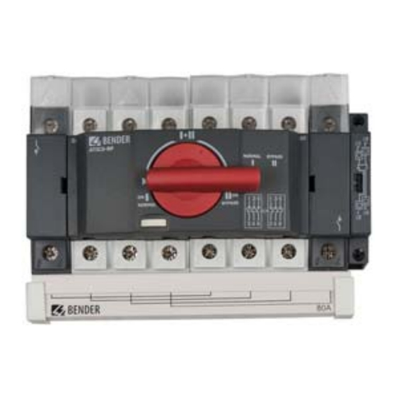
Bypass-Schalter-Set für ATICS®
Bestimmungsgemäße Verwendung
Der Bypass-Schalter ATICS-BP-... ermöglicht die Prüfung und den
Austausch des Umschaltgerätes ATICS® ohne die Stromversor-
gung der Leitung hinter der Umschalteinrichtung zu unterbre-
chen. Die Betätigung erfolgt über einen abschließbaren
Drehgriff. Das Set besteht aus:
Bypass-Schalter
•
ATICS-BP-2-63A bzw. ATICS-BP-2-80A, 2-polig, bzw.
ATICS-BP-4-80A bzw. ATICS-BP-4-125A, 4-polig
Schaltfolge: I-I+II-II,
mit Hilfskontakt, Brücke und Klemmenabdeckung
Hilfskontakt für ATICS®
•
Leuchtmelder grün/rot für Hutschienenmontage
•
Blauer Aufkleber „Bypass"
•
Sicherheitshinweise allgemein
Alle zum Einbau, zur Inbetriebnahme und zum
laufenden Betrieb eines Gerätes oder Systems er-
forderlichen Arbeiten sind durch geeignetes Fach-
personal auszuführen. Bestandteil der Geräte-
dokumentation sind neben diesem Handbuch die
„Sicherheitshinweise für Bender-Produkte".
Lebensgefahr durch Stromschlag!
Bei Berühren von unter Spannung stehenden An-
lagenteilen besteht die Gefahr
GEFAHR
• eines elektrischen Schlages,
• von Sachschäden an der elektrischen Anlage,
• der Zerstörung des Gerätes.
Stellen Sie vor Einbau des Gerätes und vor Arbei-
ten an den Anschlüssen des Gerätes sicher, dass
die Anlage spannungsfrei ist. Beachten Sie die Re-
geln für das Arbeiten an elektrischen Anlagen.
Sicherheitshinweise gerätespezifisch
Kurzschlussgefahr, wenn Leuchte „Freigabe
Bypass" nicht beachtet wird.
Ist ATICS® nicht auf die Leitung geschaltet, an die der
GEFAHR
Bypass-Schalter angeschlossen ist, kann es zu einem
Kurzschluss zwischen Leitung 1 und Leitung 2 kommen.
Der Bypass-Schalter darf nur betätigt werden, wenn die
grüne Leuchte „Freigabe Bypass" signalisiert.
Funktionsbeschreibung
I
ATICS-BP
ATICS-BP-SET_D00162_00_M_DEEN/04.2017
I
II
A
M
®
ATICS
II
I
I+II
ATICS-BP
Bypass switch set for ATICS®
Intended use
The ATICS-BP-... bypass switch set makes it possible to test and
replace the ATICS transfer switching device without interrupting
the power supply to the line downstream of the transfer switch-
ing device. The switch can be operated by means of a lockable ro-
tary handle. The set consists of:
Bypass switch
•
ATICS-BP-2-63A resp. ATICS-BP-2-80A, 2-pole, resp.
ATICS-BP-4-80A resp. ATICS-BP-4-125A, 4-pole
switching sequence: I-I+II-II,
with auxiliary contact, bridge and terminal cover
Auxiliary contact for ATICS®
•
Indicator light, green, for DIN rail mounting
•
Blue Label "Bypass"
•
Safety instructions
Only qualified personnel are permitted to carry
out the work necessary to install, commission and
run a device or system. The enclosed "Important
safety instructions for Bender products" are also
part of the equipment documentation along with
this instruction leaflet.
Risk of electrocution due to electric shock!
Touching live parts of the system carries the risk of:
• An electric shock
GEFAHR
• Damage to the electrical installation
• Destruction of the device
Before installing and connecting the device,
make sure that the installation has been de-en-
ergised. Observe the rules for working on electri-
cal installations.
Device-specific safety information
Risk of short-circuit if the "Enable Bypass" light is
ignored.
If the ATICS® is not on the line to which the bypass
DANGER
switch is connected, it is possible for a short-circuit to
occur between Line 1 and Line 2.
The bypass switch may only be operated when the
green LED lights signalling "Bypass enabled".
Functional description
I
II
B
M
®
ATICS
II
I
II
ATICS-BP
II
I
C
M
®
ATICS
II
I
1
Inhaltsverzeichnis

Verwandte Anleitungen für Bender ATICS-BP-2-SET Serie


Inhaltszusammenfassung für Bender ATICS-BP-2-SET Serie
- Seite 1 Arbeiten sind durch geeignetes Fach- run a device or system. The enclosed "Important personal auszuführen. Bestandteil der Geräte- safety instructions for Bender products" are also dokumentation sind neben diesem Handbuch die part of the equipment documentation along with „Sicherheitshinweise für Bender-Produkte“.
- Seite 2 ATICS-BP-2-…-SET, ATICS- The ATICS® transfer switching device has to be connected to Das Umschaltgerät ATICS® muss auf Leitung 1 geschaltet sein. Line 1. The auxiliary contact installed on the ATICS® recognises Der am Umschaltgerät ATICS® montierte Hilfskontakt erkennt die the switching position of the transfer switching device with the Schaltposition des Umschaltgerätes und bewirkt, dass die grüne effect that the green LED signals "Bypass enabled".
-
Seite 3: Montage Und Anschluss
ATICS-BP-2-…-SET, ATICS-BP-4-…-SET Frontansicht ATICS-BP-4-… Front view ATICS-BP-4-… ATICS-BP-4-80A ATICS-BP-4-125A Montage und Anschluss Installation and connection Das Gehäuse eignet sich: The enclosure is suitable for: - zum Einbau in Installationsverteiler DIN 43871 - installation into standard distribution panels in accordance with - zur Schnellmontage auf Hutprofilschiene DIN EN 60715 DIN 43871 - zur Schraubmontage... - Seite 4 ATICS-BP-2-…-SET, ATICS- Maßbild ATICS-BP-4-125A Dimension diagram ATICS-BP-4-125A 79,6 * 84,5 52,8 M5 / 0.2 79,6 * Alle Maße in mm All dimensions in mm Maße für Schraubmontage auf Platte Dimensions for screw mounting on plate Klemmenabdeckung demontieren Removing the terminal cover 1.
-
Seite 5: Anschluss
ATICS-BP-2-…-SET, ATICS-BP-4-…-SET Schraubmontage auf Platte Screw mounting on plate Befestigungsschrauben dürfen nicht zu dicke Provide for sufficient distance to adjacent live con- Schraubenköpfe oder Unterlegscheiben haben, da- ductors by using mounting screws with flat screw mit normgerechte Spannungsabstände zu aktiven heads and flat washers. - Seite 6 ATICS-BP-2-…-SET, ATICS- Anschlussbeispiel ATICS-2-DIO mit ATICS-BP-2-… Connection example ATICS-2-DIO with ATICS-BP-2-… ATICS-BP-SET_D00162_00_M_DEEN/04.2017...
- Seite 7 ATICS-BP-2-…-SET, ATICS-BP-4-…-SET Anschlussbeispiel ATICS-4-DIO mit ATICS-BP-4-… Connection example ATICS-4-DIO with ATICS-BP-4-… ATICS-BP-SET_D00162_00_M_DEEN/04.2017...
-
Seite 8: Bedienung
ATICS-BP-2-…-SET, ATICS- Inbetriebnahme Commissioning Zerstörungsgefahr durch falschen Anschluss Risk of destruction if connected incorrect Vor der Inbetriebnahme den ordnungsgemäßen An- Prior to commissioning ensure that the device is schluss des Geräts prüfen. properly connected. VORSICHT CAUTION Insbesondere auf Polung der Leitungen achten. In particular, be sure to observe the correct polarity of the connecting wires. -
Seite 9: Technische Daten
ATICS-BP-2-…-SET, ATICS-BP-4-…-SET Drehgriff mit Vorhängeschloss abschließen Lock the rotary handle with a padlock Der Drehgriff kann nur in der Schaltposition „I“ (Normal) abge- It is only possible to lock the rotary handle in switch position schlossen werden. Bügeldurchmesser des Vorhängeschlosses: "I"... - Seite 10 ATICS-BP-2-…-SET, ATICS- Schnellbefestigung auf Hutprofilschiene..........DIN EN 60715/IEC 60715 DIN rail mounting acc. to DIN EN 60715/IEC 60715 Gewicht ATICS-BP-…-Einzeln mit Hilfskontakt, Brücke, Klemmenabdeckung: Weight ATICS-BP-…-Single device with auxiliary contact, bridge, cover: ATICS-BP-2-63A........................0,68 kg ATICS-BP-2-63A........................0.68 kg ATICS-BP-2-80A........................0,68 kg ATICS-BP-2-80A........................0.68 kg ATICS-BP-4-80A........................0,92 kg ATICS-BP-4-80A........................0.92 kg ATICS-BP-4-125A........................2,20 kg...
-
Seite 11: Ordering Details
ATICS-BP-2-…-SET, ATICS-BP-4-…-SET Bestellangaben Ordering details Bemessungs- betriebsstrom/ Art.-Nr. / Rated Typ/Type Bezeichnung Designation Art. No. operational current I ATICS-BP- Bypass-Schalter-Set bestehend aus: Bypass switch set consisting of: AC 63 A B92057252 2-63A-SET - Bypass-Schalter 63 A einzeln, 2-polig, - Bypass switch 63 A, 2 poles, operating Schaltfolge: I-I+II-II, mit Hilfskontakt, sequence: I-I+II-II, with auxiliary con- Brücke, Klemmenabdeckung... - Seite 12 All rights reserved. Reprinting and duplicating only with Genehmigung des Herausgebers. Änderungen vorbehalten! permission of the publisher. Subject to change! © © Bender GmbH & Co. KG Bender GmbH & Co. KG Fotos: Bender Archiv. Photos: Bender archives. Bender GmbH & Co. KG Postfach 1161 •...