Herunterladen Inhalt Inhalt Diese Seite drucken
HBM T20WN Montageanleitung
Vorschau ausblenden Andere Handbücher für T20WN:
Inhaltsverzeichnis

Werbung

Verfügbare Sprachen

Verfügbare Sprachen

Mounting instructions | Montageanleitung |
Notice de montage
English
Deutsch
Francais
T20WN

Werbung

Inhaltsverzeichnis
loading

Inhaltszusammenfassung für HBM T20WN

  • Seite 1 Mounting instructions | Montageanleitung | Notice de montage English Deutsch Francais T20WN...
  • Seite 2 Hottinger Baldwin Messtechnik GmbH Im Tiefen See 45 D-64239 Darmstadt Tel. +49 6151 803-0 Fax +49 6151 803-9100 Email: info@hbm.com Internet: www.hbm.com Mat.: 7-2001.0555 DVS: A0726-14.0 05.2014 E Hottinger Baldwin Messtechnik GmbH. Subject to modifications. All product descriptions are for general information only.
  • Seite 3 Mounting instructions | Montageanleitung | Notice de montage English Deutsch Francais T20WN...
  • Seite 4: Inhaltsverzeichnis

    ... . . 10.1.2 Specifications for bellows‐type couplings ..... . A0726-14.0 T20WN...
  • Seite 5: Safety Instructions

    Safety instructions Safety instructions Use in accordance with the regulations Torque transducer T20WN is used exclusively for torque and rotation speed measurement tasks and control and adjustment tasks directly connected thereto. Use for any additional purpose shall be deemed to be not in accordance with the regulations.
  • Seite 6 The CE mark enables the manufacturer to guarantee that the product complies with the requirements of the rele­ vant EC directives (the declaration of conformity is avail­ able at http://www.hbm.com/HBMdoc). Statutory marking requirements for waste disposal National and local regulations regarding the protection of...
  • Seite 7 S The cover or cladding must not be free to rotate. S The cover or cladding must prevent access to any areas where crushing or shearing could occur, and must provide protection against any parts that may come loose. T20WN A0726-14.0...
  • Seite 8: Application

    Application Torque transducer T20WN measure static and dynamic torque and rotation speeds or angles of rotation for turning or static machine parts in any direction of rotation.
  • Seite 9: Installation

    -belt drive on the left È È È È HBM accessories: bellows‐type couplings. You will need two of these couplings. HBM accessories: bellows‐type couplings. You will need one of these couplings. Fig. 3.1 Installation options with couplings T20WN A0726-14.0...
  • Seite 10: Couplings

    H7/j6. 3.3.1 Installation position with couplings With the bellows‐type couplings, the T20WN torque transducer can be operated in any installation position (horizontal, vertical or diagonal). With vertical and diago­ nal operation, make sure that additional frames are ade­...
  • Seite 11 (see Page 23) of the torque transducer! When tightening the clamping screws, hold the coupling on the clamp element. Measuring range Tightening torque (N·m) (N·m) 0.35 0.75 Tab. 3.1 Tightening torque of the clamping screws T20WN A0726-14.0...
  • Seite 12: Electrical Connection

    Electrical connection General instructions We recommend to use shielded, low-capacitance cable from HBM for the electrical connection between torque transducer and measuring amplifier. With cable extensions it is important to ensure that a good connection is provided, with minimum contact resis­...
  • Seite 13: Cable Extension

    Cable shield Cable extension Extension cables must be the shielded, low‐capacitance type. We recommend the use of HBM cables that comply with these requirements. When using cable extensions, ensure that the connection is perfect, with the lowest possible contact resistance and good insulation.
  • Seite 14: Shielding Design

    (compensating currents), separate the connections between the zero operating voltage and the housing ground on the measuring amplifier and connect a potential equalisation line between the transducer housing and the amplifier housing (copper wire, 10 mm conductor cross‐section). A0726-14.0 T20WN...
  • Seite 15: Load-Carrying Capacity

    Load‐carrying capacity Load‐carrying capacity The torque transducer T20WN is suitable for measuring static and dynamic torque. Nominal torque can be exceeded statically up to the limit torque. If nominal torque is exceeded, additional irregular loading is not permissible. This includes longitudinal forces, lateral forces and bending moments.
  • Seite 16: Maximum Rotation Speed

    80 % M vibration bandwidth Lower torque limit Fig. 5.1 Permissible dynamic loading Maximum rotation speed Torque transducer T20WN allows torque measurements up to a rotation speed of 10 000 min and rotation speed measurements up to 3000 min A0726-14.0 T20WN...
  • Seite 17: Displaying Torque And Direction Of Rotation

    (0...+10 V). Direction of rotation The sign on the display indicates the direction of rotation. With HBM measuring amplifiers, the output voltage or display is positive, if the transducer shaft is turning clockwise, looking at the measuring side.
  • Seite 18: Maintenance

    Maintenance Maintenance Torque transducer T20WN is largely maintenance free. We recommend that the low‐friction special bearing should be replaced at the Darmstadt factory, after approx. 20 000 working hours. The calibration will also be checked at this time. A0726-14.0 T20WN...
  • Seite 19: Dimensions

    3 170 45 56 26 26 65 M4/8 M4/8 42 15 40 3 170 45 56 26 26 65 M4/8 M4/8 42 15 40 3 170 45 56 26 26 65 M4/8 M4/8 Size of thread/depth of thread T20WN A0726-14.0...
  • Seite 20: Specifications

    Specifications Specifications Type T20WN Accuracy class Torque measuring system Nominal torque N·m 0.1 0.2 0.5 50 100 200 Nominal sensitiv­ (Nominal signal range between torque = zero and nominal torque) "0.2 Characteristic tol­ erance (deviation of the actual output at M of the nominal sig­...
  • Seite 21 Nominal power con­ < 2.4 sumption Linearity deviation <"0.1 including hystere­ sis, related to the nominal (rated) sensitivity Rel. standard <"0.05 deviation of the reproducibility, according to DIN 1319, by refer­ ence to variation of the output signal T20WN A0726-14.0...
  • Seite 22 Load resistance > 10 μs Group delay time < 3 With 1.5 m cable between T20WN and VK20A junction box (The group delay time depends on the connected impedance / cable & evaluating device without VK20A) Maximum measur­ 3000 able rotation...
  • Seite 23 DIN IEC 68; Part 2‐27; IEC 68‐2‐27‐1987 Number 1000 Duration Acceleration (half- sine) Vibration resis­ tance, test sever­ ity level according to DIN IEC 68, Part 2‐6: IEC 68‐2‐6‐1982 Frequency range 5...65 Duration T20WN A0726-14.0...
  • Seite 24 0.32 0.3 0.35 0.2 0.26 0.35 μm Max. limits for rel­ + 4500 n in rpm ative shaft vibra­ tion (peak‐to‐ peak) Effect. vibration mm/s n in rpm velocity in the area of the housing in accordance with VDI 2056 A0726-14.0 T20WN...
  • Seite 25 1 % of nominal torque. Please comply with the maximum torque (T ) of the couplings. Kmax Nominal torque must not be exceeded. Relative undulation following DIN 45670/VDI 2059. T20WN A0726-14.0...
  • Seite 26: Accessories

    Accessories S Transducer connection cable, 5 m long, order no. 3‐3301.0158 S Transducer connection cable, 10 m long, order no. 3‐3301.0159 S Cable socket, 12‐pin (linkage), order no. 3‐3312.0268 S Terminal box, order no. 1‐VK20A S Bellows‐type couplings A0726-14.0 T20WN...
  • Seite 27: 10.1 Bellows-Type Couplings

    10.1.1 Dimensions for the bellows‐type couplings (in mm) For measuring ranges 0.1 N⋅m...1 N⋅m For measuring ranges 2 N⋅m...200 N⋅m Disassembly slot Overall length Measuring side A Drive side B Part Side Meas. range variable min...max (N·m) 3-4412. 3...9 0001 3-4412. 3...9 0002 T20WN A0726-14.0...
  • Seite 28: 10.1.2 Specifications For Bellows-Type Couplings

    0008 10.1.2 Specifications for bellows‐type couplings Meas. Torque Mass Weight Torsional Max. permissible offset Range coupling moment stiffness axial radial angular of inertia Kmax (mm) (mm) (degree) (N·m) (N·m) (kg·cm (kN·m/rad) 0.012 0.21 0.018 0.38 0.27 9.05 0.15 A0726-14.0 T20WN...
  • Seite 29 (kN·m/rad) (kN·m/rad) 0.15 1600 0.15 3800 0.15 Measuring Spring stiffness Material Tightening torque range clamping screws hub and fixing ring (N·m) axial (N/mm) radial (N/mm) (N·m) 13.4 47.7 0.35 27.4 84.3 0.75 20.6 0.75 Aluminium 33.3 Steel 2940 T20WN A0726-14.0...
  • Seite 30 Accessories A0726-14.0 T20WN...
  • Seite 31 Mounting instructions | Montageanleitung Notice de montage English Deutsch Francais T20WN...
  • Seite 32 ....10.1.2 Technische Daten Faltenbalg-Kupplungen ..... A0726-14.0 T20WN...
  • Seite 33: Sicherheitshinweise

    Sicherheitshinweise Sicherheitshinweise Bestimmungsgemäßer Gebrauch Die Drehmoment‐Messwelle T20WN ist ausschließlich für Drehmoment‐ und Drehzahl‐Messaufgaben und direkt damit verbundene Steuerungs‐ und Regelungsaufgaben zu verwenden. Jeder darüber hinausgehende Gebrauch gilt als nicht bestimmungsgemäß. Zur Gewährleistung eines sicheren Betriebes darf der Aufnehmer nur nach den Angaben in der Bedienungsan­...
  • Seite 34 Kursive Schrift kennzeichnet Hervorhebungen im Siehe … Text und kennzeichnet Verweise auf Kapitel, Bilder oder externe Dokumente und Dateien. CE‐Kennzeichnung Mit der CE‐Kennzeichnung garantiert der Hersteller, dass sein Produkt den Anforderungen der relevanten EG‐ Richtlinien entspricht (die Konformitätserklärung finden Sie unter http://www.hbm.com/HBMdoc). A0726-14.0 T20WN...
  • Seite 35 Qualifiziertes Personal sind Personen, die mit Aufstel­ lung, Montage, Inbetriebsetzung und Betrieb des Produk­ tes vertraut sind und über die ihrer Tätigkeit entspre­ chende Qualifikationen verfügen. Unfallverhütung Entsprechend den einschlägigen Unfallverhütungsvor­ schriften der Berufsgenossenschaften ist nach der Mon­ T20WN A0726-14.0...
  • Seite 36: Anwendung

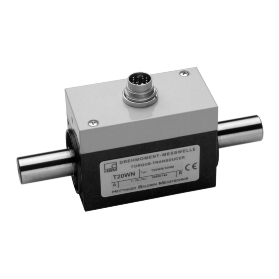
    Bau der Maschine oder bereits vorhandene Schutzvorkehrungen ausreichend gesichert sind. Anwendung Die Drehmoment‐Messwelle T20WN misst statische und dynamische Drehmomente und Drehzahlen oder Dreh­ winkel an drehenden oder ruhenden Maschinenteilen bei beliebiger Drehrichtung. Sie sind konzipiert für kleine bis mittlere Drehmomente, wie sie z.
  • Seite 37: Montage

    È È Stirnmontage, È È È È È rechts Vollkupp­ lung -links È È Riementrieb È È HBM‐Zubehör: Faltenbalg‐Kupplungen. Benötigt werden zwei der angebotenen Kupplungen. HBM‐Zubehör: Faltenbalg‐Kupplungen. Benötigt wird eine der angebotenen Kupplungen. Abb. 3.1 Montagemöglichkeiten mit Kupplungen T20WN A0726-14.0...
  • Seite 38: Kupplungen

    S Die Wellendurchmesser mit j6‐Toleranz ausführen, damit sich die Vorzugspassung H7/j6 ergibt. 3.3.1 Einbaulage mit Kupplungen Die Drehmoment‐Messwelle T20WN kann mit den Fal­ tenbalg‐Kupplungen in beliebiger Einbaulage (horizontal, vertikal oder schräg) betrieben werden. Achten Sie bitte beim vertikalen und schrägen Betrieb darauf, dass zu­...
  • Seite 39 Bei der Kupplungsmontage dürfen die zulässigen Längs‐ und Querkräfte sowie Grenzbiegemomente (siehe Seite 23) der Drehmoment‐Messwelle nicht überschritten werden! Beim Anziehen der Spannschrauben die Kupplung am Klemmelement festhalten. Messbereich Anziehdrehmoment (N·m) (N·m) 0,35 0,75 Tab. 3.1 Anziehdrehmoment der Spannschrauben T20WN A0726-14.0...
  • Seite 40: Elektrischer Anschluss

    Elektrischer Anschluss Allgemeine Hinweise Für die elektrische Verbindung zwischen Drehmomen­ taufnehmer und Messverstärker empfehlen wir die ge­ schirmten und kapazitätsarmen Messkabel von HBM zu verwenden. Achten Sie bei Kabelverlängerungen auf eine einwand­ freie Verbindung mit geringstem Übergangswiderstand und guter Isolation. Alle Steckverbindungen oder Über­...
  • Seite 41: Kabelverlängerung

    Kabelschirm Kabelverlängerung Verlängerungskabel müssen abgeschirmt und kapazität­ sarm sein. Wir empfehlen die Verwendung von HBM‐Ka­ beln, die diese Voraussetzungen erfüllen. Bei Kabelverlängerungen ist auf einwandfreie Verbindung mit geringstem Übergangswiderstand und gute Isolation zu achten. Deshalb sollen alle Verbindungen gelötet, zu­...
  • Seite 42: Schirmungskonzept

    Störungen beeinflussen das Messsignal nicht. Bei Störungen durch Potentialunterschiede (Ausgleichs­ ströme) trennen Sie am Messverstärker die Verbindun­ gen zwischen Betriebsspannungsnull und Gehäuse­ masse und legen Sie eine Potentialausgleichsleitung zwischen Aufnehmergehäuse und Messverstärkerge­ häuse (Kupferleitung, 10 mm Leitungsquerschnitt). A0726-14.0 T20WN...
  • Seite 43: Belastbarkeit

    Belastbarkeit Belastbarkeit Die Drehmoment‐Messwelle T20WN eignet sich zum Messen statischer und dynamischer Drehmomente. Das Nenndrehmoment darf statisch bis zum Grenzdreh­ moment überschritten werden. Wird das Nenndrehmo­ ment überschritten, sind weitere irreguläre Belastungen nicht zulässig. Hierzu zählen Längskräfte, Querkräfte und Biegemomente. Die Grenzwerte finden Sie im Kapitel 9 „Technische Daten“, Seite 18.
  • Seite 44: Drehzahlgrenzen

    Belastungsbereichs liegen. Drehmoment M in % Obere Drehmomentgrenze 80 % M Schwingbreite Untere Drehmomentgrenze Abb. 5.1 Zulässige dynamische Belastung Drehzahlgrenzen Die Drehmoment‐Messwellen T20WN erlauben Drehmo­ mentmessungen bis zu einer Drehzahl von 10 000 min und Drehzahlmessungen bis 3000 min A0726-14.0 T20WN...
  • Seite 45: Drehmoment- Und Drehrichtungsanzeige

    Wird ein rechtsdrehendes Moment (im Uhrzeigersinn) eingeleitet, steht ein positives Ausgangssignal (0...+10 V) Drehrichtung Das Vorzeichen der Anzeige gibt die Drehrichtung an. Bei HBM‐Messverstärkern ist die Ausgangsspannung bzw. Anzeige positiv, wenn man die Messwelle mit Blick auf die Messseite im Uhrzeigersinn dreht. Markierung der Messseite Abb.
  • Seite 46: Wartung

    Wartung Wartung Die Drehmoment‐Messwelle T20WN ist weitgehend war­ tungsfrei. Wir empfehlen, die reibungsarmen Speziallager nach ca. 20 000 Betriebsstunden im Werk Darmstadt wechseln zu lassen. Bei dieser Gelegenheit wird auch die Kalibrierung überprüft. A0726-14.0 T20WN...
  • Seite 47: Abmessungen

    46 M3/6 M3/6 42 15 40 3 170 45 56 26 26 65 M4/8 M4/8 42 15 40 3 170 45 56 26 26 65 M4/8 M4/8 42 15 40 3 170 45 56 26 26 65 M4/8 M4/8 Gewindedurchmesser/Gewindetiefe T20WN A0726-14.0...
  • Seite 48: Technische Daten

    Technische Daten Technische Daten T20WN Genauigkeits­ klasse Drehmoment‐Messsystem Nenndreh­ NVm 0,1 0,2 0,5 50 100 200 moment M Nennkennwert (Nennsignal­ spanne zwischen Drehmo­ ment = Null und Nenndreh­ moment) "0,2 Kennwerttole­ ranz (Abweichung der tatsächlichen Aus­ gangsgröße bei von der Nenn­...
  • Seite 49 Nullsignal, bezogen auf den Nennkennwert Energieversor­ gung Nennversor­ 12 (DC); (10,8...13,2) gungsspannung (Schutzkleinspan­ nung) Auslösen des 5...13,2 Kontrollsignals Stromaufnahme < 0,2 im Messbetrieb Nennaufnahme­ < 2,4 leistung Linearitäts­ <"0,1 abweichung einschließlich Hysterese, bez. auf den Nenn­ kennwert T20WN A0726-14.0...
  • Seite 50 Impulsstabilität Lastwiderstand > 10 μs Gruppenlaufzeit < 3 bei 1,5 m Kabel zwischen T20WN und Klemmenkasten VK20A (ohne VK20A ist die Gruppenlaufzeit abhängig von der angeschlos­ senen Impedanz / Kabel & Auswertegerät) Maximal mess­ 3000 bare Drehzahl Allgemeine Angaben Störfestigkeit...
  • Seite 51 Schutzart nach IP40 EN 60 529 Gewicht, ca. 0,17 0,60 ° Nenntemperatur­ +5...+45 bereich ° Gebrauchstem­ 0...+60 peraturbereich ° Lagerungstem­ -5...+70 peraturbereich Stoßbeständig­ keit, Prüfschärfe­ grad nach DIN IEC 68; Teil 2‐27; IEC 68‐2‐27‐1987 Anzahl 1000 Dauer Beschleunigung (Halbsinus) T20WN A0726-14.0...
  • Seite 52 0,12 0,12 0,12 0,23 0,93 1,9 moment Schwingbreite nach DIN 50 100 (Spitze/Spitze) Mechanische Werte Drehsteifigkeit c kN⋅m/ 0,03 0,03 0,03 0,05 0,07 0,91 1,9 3,25 21,9 32,6 Verdrehwinkel Grad 0,2 0,38 0,96 0,32 0,3 0,35 0,2 0,26 0,35 bei M A0726-14.0 T20WN...
  • Seite 53 Messergebnis können sich die zul. Biegemomente, Längs‐ und Querkräfte wie ca. 1 % des Nenndrehmomentes auswirken. Bitte beachten Sie das maximale Moment (T ) der Kupplungen. Kmax Das Nenndrehmoment darf nicht überschritten werden. Relative Wellenschwingungen in Anlehnung an DIN 45670/VDI 2059. T20WN A0726-14.0...
  • Seite 54: Zubehör

    Zubehör Zubehör S Aufnehmer‐Anschlusskabel, 5 m lang, Bestell‐Nr. 3‐3301.0158 S Aufnehmer‐Anschlusskabel, 10 m lang, Bestell‐Nr. 3‐3301.0159 S Kabeldose, 12polig (Binder), Bestell‐Nr. 3‐3312.0268 S Klemmenkasten, Bestell‐Nr. 1‐VK20A S Faltenbalg‐Kupplungen A0726-14.0 T20WN...
  • Seite 55: 10.1 Faltenbalg-Kupplungen

    Zubehör 10.1 Faltenbalg‐Kupplungen 10.1.1 Abmessungen Faltenbalg‐Kupplungen (in mm) Für Messbereiche 0,1 N⋅m...1 N⋅m Für Messbereiche 2 N⋅m...200 N⋅m Demontagenut Gesamtlänge Messseite A Antriebsseite B Mess­ Teile- Side bereich variabel min...max (N·m) 3-4412. 3...9 0001 3-4412. 3...9 0002 T20WN A0726-14.0...
  • Seite 56: 10.1.2 Technische Daten Faltenbalg-Kupplungen

    Grenzen. Bohrungstoleranz H7. 10.1.2 Technische Daten Faltenbalg-Kupplungen Mess­ Dreh­ Massen­ Gewicht Dreh­ Max. Zulässiger Versatz bereich moment trägheits­ steifigkeit axial radial angular Kupplung moment (mm) (mm) (Grad) Kmax (N·m) (N·m) (kg·cm (kN·m/rad) 0,012 0,21 0,018 0,38 0,27 A0726-14.0 T20WN...
  • Seite 57 (kg·cm (kg·cm (kN·m/rad) (kN·m/rad) 9,05 0,15 0,15 1600 0,15 3800 0,15 Messbereich Federsteife Anzugsmoment Werkstoff Nabe und Befes­ Spannschrauben tigungsring (N·m) axial (N/mm) radial (N/mm) (N·m) 13,4 47,7 0,35 27,4 84,3 0,75 20,6 0,75 Aluminium 33,3 Stahl 2940 T20WN A0726-14.0...
  • Seite 58 Zubehör A0726-14.0 T20WN...
  • Seite 59 Mounting instructions | Montageanleitung | Notice de montage English Deutsch Francais T20WN...
  • Seite 60 ........10.1.1 Dimensions des accouplements à soufflet (en mm) ... . . 10.1.2 Caractéristiques techniques des accouplements à soufflet ..A0726-14.0 T20WN...
  • Seite 61: Consignes De Sécurité

    Consignes de sécurité Consignes de sécurité Utilisation conforme L'utilisation de couplemètre à arbre de torsion T20WN est exclusivement réservée aux travaux de mesure de couple et de vitesse de rotation et aux travaux de commande et de réglage directement associés. Toute autre application est considérée comme non conforme.
  • Seite 62 Pour mettre en valeur certains mots du texte, Voir … ces derniers sont écrits en italique. Label CE Par le label CE, le fabricant garantit que son produit satisfait aux conditions des principales directives CE (cf. déclaration de conformité à http://www.hbm.com/HBMdoc). A0726-14.0 T20WN...
  • Seite 63 Ceci vaut également pour l'utilisation des accessoires. Sont considérées comme personnel qualifié les personnes familiarisées avec l'installation, le montage, la mise en service et l'exploitation du produit, et disposant des qualifications correspondantes. T20WN A0726-14.0...
  • Seite 64 Les instructions susmentionnées peuvent être ignorées uniquement si la construction de la machine ou les installations de sécurité existantes sont déjà suffisantes pour protéger la machine et ses alentours. A0726-14.0 T20WN...
  • Seite 65: Application

    Application Application Le couplemètre à arbre de torsion T20WN permet de mesurer des couples et vitesses ou angles de rotation statiques et dynamiques sur des pièces de machines immobiles ou en rotation, quel que soit le sens de rotation. Il est conçu pour des couples faibles à moyens tels que ceux présents par exemple dans les bancs...
  • Seite 66 È È È pignon à courroie à gauche È Accessoires HBM : accouplements à soufflet. Ce type d'accouplement s'utilise par paire. Accessoires HBM : accouplements à soufflet. Ce type d'accouplement s'utilise seul. Fig. 3.1 Possibilités de montage avec accouplements A0726-14.0...
  • Seite 67: Accouplements

    Montage Accouplements Pour le montage de couplemètre à arbre de torsion, HBM propose des accouplements à soufflet. Dans la livraison, les accouplements et le couplemètre à arbre de torsion sont séparés. Lors du montage, il est nécessaire de respecter les points suivants : S Ne serrer les vis de bridage des accouplements qu'une fois les arbres montés dans les moyeux...
  • Seite 68 (voir page 25) du couplemètre à arbre de torsion ! Lors du serrage des vis de bridage, maintenir l'accou­ plement sur la pièce de serrage. A0726-14.0 T20WN...
  • Seite 69: Raccordement Électrique

    Pour le raccordement électrique entre le capteur de couple et l'amplificateur de mesure nous recommandons d'utiliser des câbles de mesure blindés de faible capacité de HBM. Pour les prolongations de câble, il faut veiller à une parfaite connexion avec des résistances de transition minimes et à...
  • Seite 70: Prise De Raccordement

    Ils peuvent ainsi être raccordés à l'électronique de mesure appropriée via le câble de raccordement du capteur (Accessoires, voir page 24). La table ci‐dessous vous fournit le code de raccordement pour les câbles de raccordement du capteur : A0726-14.0 T20WN...
  • Seite 71: Rallonge De Câble

    Blindage de câble Rallonge de câble Toute rallonge doit être blindée et de faible capacité. Nous vous conseillons d'utiliser les câbles HBM qui remplissent ces conditions. En cas d'utilisation de rallonges, veiller à obtenir une connexion correcte, c'est‐à‐dire présentant une faible résistance de contact et une bonne isolation.
  • Seite 72: Concept De Blindage

    (conducteur en cuivre d'une section de 10 mm A0726-14.0 T20WN...
  • Seite 73: Capacité De Charge

    Capacité de charge Capacité de charge Le couplemètre à arbre de torsion T20WN permet de mesurer des couples statiques et dynamiques. En mesure statique, il est possible de dépasser le couple nominal jusqu'à atteindre le couple limite. Toutefois, le dépassement du couple nominal interdit toute autre charge anormale, notamment les forces axiales et transverses et les moments de flexion.
  • Seite 74: Vitesses De Rotation Limites

    Limite inférieure Fig. 5.1 Charge dynamique admissible Vitesses de rotation limites Les couplemètres à arbre de torsion T20WN peuvent mesurer des couples jusqu'à une vitesse de 10 000 min et mesurer des vitesses de rotation jusqu'à 3000 min A0726-14.0 T20WN...
  • Seite 75: Affichage Du Couple Et Du Sens De Rotation

    Fig. 6.1 Sens de rotation correspondant à l'affichage positif Entretien Le couplemètre à arbre de torsion T20WN est quasiment sans entretien. Il est conseillé de faire changer à l'usine de Darmstadt le palier spécial sans frottement après env. 20 000 heures de service. Le calibrage sera également vérifié...
  • Seite 76: Dimensions

    42 15 40 3 170 45 56 26 26 65 M4/8 M4/8 42 15 40 3 170 45 56 26 26 65 M4/8 M4/8 42 15 40 3 170 45 56 26 26 65 M4/8 M4/8 Diamètre/profondeur du filetage A0726-14.0 T20WN...
  • Seite 77: Caractéristiques Techniques

    Caractéristiques techniques Caractéristiques techniques Type T20WN Classe de préci­ sion Système de mesure de couple Couple nominal NVm 0,1 0,2 0,5 50 100 200 Sensibilité nomi­ nale (plage de signal nominal entre couple = zéro et couple nominal) "0,2 Tolérance de sensibilité...
  • Seite 78 à la sensi­ bilité nominale Alimentation Tension d'alimen­ 12 (C.C.) ; (10,8...13,2) tation nominale (basse tension de protection) Déclenchement 5...13,2 du signal de con­ trôle Consommation de < 0,2 courant en mode mesure Puissance < 2,4 absorbée nomi­ nale A0726-14.0 T20WN...
  • Seite 79 μs Durée de temps < 3 de groupe Avec 1,5m de câble entre T20WN et boîtier de rac­ cordement VK20A (sans VK20A, le temps de propagation de groupe dépend de l'impédance raccordée / câble & dispositif d'exploitation) T20WN A0726-14.0...
  • Seite 80 (EN55011) Tension RF Classe B Intensité du Classe B champ RF Indice de protec­ IP 40 tion selon EN 60 529 Poids, env. 0,17 0,60 ° Plage nominale +5...+45 de température ° Plage utile de 0...+60 température A0726-14.0 T20WN...
  • Seite 81 2‐6: IEC 68‐2‐6‐1982 Plage de 5...65 fréquence Durée Accélération (amplitude) Limites de charge Couple limite par rapport à M Couple de rup­ > 280 ture par rapport à Force axiale 0,34 1,1 1,75 2,75 5,3 7,6 12,5 limite T20WN A0726-14.0...
  • Seite 82 0,32 0,3 0,35 0,2 0,26 0,35 pour M μm Amplitude maxi­ + 4500 n en min mum de vib­ ration du rotor (crête‐crête) Vitesse effect. mm/s n en min des vibrations au niveau du boîtier, selon VDI 2056 A0726-14.0 T20WN...
  • Seite 83 1 % du couple nominal. Veuillez respecter le moment maximal (T ) des accouplements. Kmax Le couple nominal ne doit pas être dépassé. Vibrations sinusoïdales relatives en accord avec la norme DIN 45670/VDI 2059. T20WN A0726-14.0...
  • Seite 84: Accessoires

    Nº de commande 3‐3301.0158 S Câble de raccordement du capteur, long. 10 m, Nº de commande 3‐3301.0159 S Prise femelle, 12 pôles (Binder), Nº de commande 3‐3312.0268 S Boîte de bornes, Nº de commande 1‐VK20A S Accouplements à soufflet A0726-14.0 T20WN...
  • Seite 85: 10.1 Accouplements À Soufflet

    Pour les étendues de mesure 0,1 N⋅m...1 N⋅m Pour les étendues de mesure 2 N⋅m...200 N⋅m Rainure de démontage Longueur totale Côté mesure A Côté entraînement B Etendue Nº de Côté com­ mesure mande variable min...max (N·m) 3-4412. 3...9 0001 3-4412. 3...9 0002 T20WN A0726-14.0...
  • Seite 86: Caractéristiques Techniques Des Accouplements À Soufflet

    0008 10.1.2 Caractéristiques techniques des accouplements à soufflet Etendue Couple Moment Poids Raideur Déplacement maxi. admissible d'accou- d'inertie torsion­ mesure plement nelle axial radial angulaire Kmax (mm) (mm) (Degré) (N·m) (N·m) (kg·cm (kN·m/rad) 0,012 0,21 0,018 0,38 0,27 A0726-14.0 T20WN...
  • Seite 87 3800 0,15 Etendue de Rigidité élastique Matériau Couple de serrage mesure des vis de bridage Moyeu et anneau de (N·m) axial (N/mm) radial (N/mm) (N·m) fixation 13,4 47,7 0,35 27,4 84,3 0,75 20,6 0,75 Aluminium 33,3 Acier 2940 T20WN A0726-14.0...
  • Seite 88 HBM Test and Measurement Tel. +49 6151 803-0 Fax +49 6151 803-9100 info@hbm.com measure and predict with confidence...

Inhaltsverzeichnis