Inhaltsverzeichnis
Werbung
Verfügbare Sprachen
Verfügbare Sprachen
Quicklinks
Junior 1 / Junior 1s / Junior 2
Linearantrieb / Linear actuator / Vérin électrique /
Motore lineare / Motor lineal
DE
EN
FR
IT
ES
Montageanleitung
Bitte bewahren Sie die Montageanleitung auf!
Operating instructions
Please take care of the operating instructions!
Instructions de montage
Veuillez conserver les présentes instructions de montage!
Istruzioni per l'uso
La preghiamo di conservare le istrzioni per l'uso!
Instrucciones de montaje
Por favor, conserve estas instrucciones de montaje!
Stand 04/2016, TN: 2010851
Werbung
Inhaltsverzeichnis

Verwandte Anleitungen für elero Junior 1


Inhaltszusammenfassung für elero Junior 1
- Seite 1 Junior 1 / Junior 1s / Junior 2 Linearantrieb / Linear actuator / Vérin électrique / Motore lineare / Motor lineal Montageanleitung Bitte bewahren Sie die Montageanleitung auf! Operating instructions Please take care of the operating instructions! Instructions de montage Veuillez conserver les présentes instructions de montage! Istruzioni per l‘uso La preghiamo di conservare le istrzioni per l‘uso! Instrucciones de montaje...
- Seite 2 Die deutsche Montageanleitung ist die Originalfassung. Alle anderssprachigen Dokumente stellen Übersetzungen der Originalfassung dar. Änderungen vorbehalten. Alle Rechte für den Fall der Patent-, Gebrauchs- muster- oder Geschmacksmustereintragung vorbehalten. Translation from the original German version. All other documents in different languages are translations of the original version.
-
Seite 3: Inhaltsverzeichnis
3.3.2 Hinweise zur Selbsthemmung ................ 14 Montage .................... 15 Mechanische Befestigung ................16 Elektrischer Anschluss..................17 Optionale Anbauteile ..................18 4.3.1 Option Bremse....................18 4.3.2 Option Potentiometer..................18 4.3.3 Option Absolutwertgeber 0...10V ..............19 4.3.4 Option Drehimpulsgeber................. 21 4.3.5 Option Drehimpulsgeber elero................ 22... - Seite 4 Inhaltsverzeichnis 4.3.6 Option Motorsteuerplatine (MSP) ..............23 4.3.7 Option Faltenbalg ................... 24 Endschalter..................... 24 4.4.1 Zulässiger Verstellbereich der Endschalter ............ 25 4.4.2 Einstellung der Endschalter ................25 4.4.3 Betrieb des Geräts..................27 Allgemeines Maßblatt ..................28 Einbauerklärung ................29 Entsorgung ..................30 Verschrottung ....................
-
Seite 5: Allgemeines
Allgemeines Allgemeines Hinweise zur Montageanleitung Die inhaltliche Gliederung ist an den Lebensphasen des Linearantriebs (im Folgenden als „Gerät“ bezeichnet) orientiert. Der Hersteller behält sich Änderungen der in dieser Montageanleitung genann- ten technischen Daten vor. Sie können im Einzelnen von der jeweiligen Ausfüh- rung des Geräts abweichen, ohne dass die sachlichen Informationen grundsätz- lich verändert werden und an Gültigkeit verlieren. -
Seite 6: Vorhersehbare Fehlanwendung
Allgemeines Ist eine mittel- oder unmittelbare Gefährdung von Personen nicht auszuschlie- ßen, müssen zwingend zusätzliche Maßnahmen (z. B. Abdeckung, Absperrung usw.) getroffen werden, die das Risikopotential entsprechend minimieren. Für die aus der nicht bestimmungsgemäßen Verwendung des Geräts entstehen- den Schäden haftet allein der Betreiber. Für Personen- und Sachschäden, die durch Missbrauch oder aus Verfahrensfehlern, durch unsachgemäße Bedienung und Inbetriebnahme entstehen, übernimmt der Hersteller keine Haftung. -
Seite 7: Kundendienst Des Herstellers
Das Gerät darf im Fehlerfall nur durch den Hersteller repariert werden. Die Anschrift zum Einsenden an den Kundendienst finden Sie auf der hinteren Um- schlagseite. Sollten Sie das Gerät nicht direkt von elero bezogen haben, wenden Sie sich an den Hersteller der Maschine oder den Lieferanten des Geräts. Vor der Demontage des Geräts ist die Anlage mechanisch zu sichern. Das Ge- rät darf nicht gewaltsam von der Anlage getrennt werden. -
Seite 8: Sicherheit
Sicherheit Sicherheit Allgemeine Sicherheitshinweise Diese Montageanleitung enthält alle Sicherheitshinweise, die zur Vermei- dung und Abwendung von Gefahren im Umgang mit dem Gerät in den ein- zelnen Lebenszyklen zu beachten sind. Bei Einhaltung aller aufgeführten Sicherheitshinweise ist eine sichere Benutzung des Geräts gewährleistet. 2.1.1 Gestaltung der Sicherheitshinweise Die Sicherheitshinweise in diesem Dokument werden durch Sicherheitssymbole gekennzeichnet und sind nach dem SAFE-Prinzip gestaltet. Sie enthalten Anga- ben zu Art und Quelle der Gefahr, zu möglichen Folgen sowie zur Abwendung der Gefahr. - Seite 9 Sicherheit Die folgende Tabelle beschreibt die in vorliegender Montageanleitung verwen- deten Piktogramme, die zur bildlichen Darstellung der Gefahrensituation im Zusammenhang mit dem Symbol für die Gefahrenstufe verwendet werden. Symbol Bedeutung Gefahr durch elektrische Spannung, Stromschlag: Dieses Symbol weist auf Gefahren durch elektrischen Strom hin. Gefahr des Quetschens und Erschlagens von Personen: Dieses Symbol weist auf Gefahren hin, bei denen der ge- samte Körper oder einzelne Körperteile gequetscht oder verletzt werden können.
-
Seite 10: Sicherheitsgrundsätze
Sicherheit Sicherheitsgrundsätze Das Gerät ist nach dem Stand der Technik und den anerkannten sicherheits- technischen Regeln gebaut und ist betriebssicher. Bei der Ausführung des Ge- räts wurden die grundlegenden Sicherheits- und Gesundheitsanforderungen der zutreffenden Gesetze, Normen und Richtlinien angewandt. Die Sicherheit des Geräts wird durch die Einbauerklärung bestätigt. -
Seite 11: Allgemeine Betreiberpflichten
Sicherheit Allgemeine Betreiberpflichten Der Betreiber ist verpflichtet, das Gerät nur in einwandfreiem und be- ❏ triebssicherem Zustand einzusetzen. Er muss dafür sorgen, dass neben den Sicherheitshinweisen in der Montageanleitung die allgemeingülti- gen Sicherheits- und Unfallverhütungsvorschriften, die Vorgaben der DIN VDE 0100 sowie die Bestimmungen zum Umweltschutz des jeweiligen Einsatzlandes beachtet und eingehalten werden. Der Betreiber ist dafür verantwortlich, dass alle Arbeiten mit dem Gerät nur ❏... -
Seite 12: Sicherheitshinweise Zum Technischen Zustand
Sicherheit Sicherheitshinweise zum technischen Zustand Das Gerät ist vor dem Einbau auf Beschädigungen und ordnungsgemäßen ❏ Zustand zu prüfen. Der Betreiber ist verpflichtet, das Gerät nur in einwandfreiem und betriebs- ❏ sicherem Zustand zu betreiben. Der technische Zustand muss jederzeit den gesetzlichen Anforderungen entsprechen. Werden Gefahren für Personen oder Änderungen im Betriebsverhalten er- ❏... -
Seite 13: Sicherheitshinweise Zum Betrieb
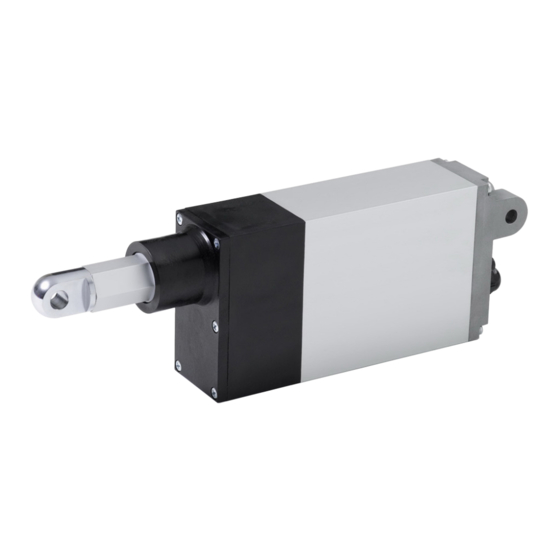
Sicherheit Sicherheitshinweise zum Betrieb Der Betreiber des Geräts ist verpflichtet, sich vor der ersten Inbetriebnahme ❏ vom sicheren und ordnungsgemäßen Zustand des Geräts zu überzeugen. Das ist auch während des Betriebs des Geräts in vom Betreiber festzule- ❏ genden, regelmäßigen Zeitabständen erforderlich. Im Fehlerfall, bei Fehlanwendung und/oder bei nicht ordnungsgemäßem ❏... - Seite 14 Produktbeschreibung Produktbeschreibung Allgemeines Das Gerät ist ein elektromechanischer Schubspindelantrieb. Es führt im Betrieb Linearbewegungen aus. Abb. 1 Bestandteile eines Geräts Optionen (z. B. Potentiometer oder Drehimpulsgeber) Befestigung Kolbenseite Befestigung Gehäuseseite Endschalterjustierschrauben elektrischer Anschluss Gehäusedeckel Produktvarianten Das Gerät kann in verschiedenen Konfigurationen bezogen werden. Die genaue Konfiguration Ihres Geräts können Sie der Auftragsbestätigung entnehmen.
-
Seite 15: Produktbeschreibung
Produktbeschreibung Technische Daten Alle Angaben in diesem Kapitel beziehen sich auf eine Umgebungstemperatur von 20 °C. 3.3.1 Zusammenstellung technischer Parameter Technische Daten Junior 1 Junior 1s Junior 2 Bemessungsspannung 24 V DC Bemessungsstrom bis 1,2 A bis 2,5 A bis 6 A Last dynamisch (N) 50 –... -
Seite 16: Hinweise Zur Selbsthemmung
Produktbeschreibung 3.3.2 Hinweise zur Selbsthemmung WARNUNG Verletzungsgefahr durch Verlust der Selbsthemmung. Quetschen und Erschlagen von Personen möglich. • Gerät mit Bremse verwenden. ACHTUNG Beschädigung des Geräts oder der Kundenanlage durch Verlust der Selbsthemmung möglich. • Gerät mit Bremse verwenden. Bei den Geräten unterscheidet man zwischen dynamischer und statischer Selbsthemmung. Die dynamische Selbsthemmung entsteht aus der Bewe- gung und die statische Selbsthemmung entsteht im Stillstand des Geräts. - Seite 17 Montage Montage WARNUNG Verletzungsgefahr durch Witterungseinflüsse. Erfrierungen und Verbrennungen der Haut möglich. • Persönliche Schutzausrüstung tragen. WARNUNG Verletzungsgefahr durch falsch dimensionierte Aufnahmen. Quetschen und Erschlagen von Personen möglich. • Ausschließlich zur Dimension der Aufnahmen passendes Befestigungsmate- rial verwenden. • Die Gegenaufnahmen (kundenseitig) müssen mindestens für die Kräfte aus- gelegt sein, für die das Gerät konzipiert wurde.
-
Seite 18: Montage
Montage ACHTUNG Beschädigung des Geräts durch Blockierung der Kolbenstange. • Der Verfahrweg des Kolbens muss immer frei verfahrbar sein. • Der Schwenkbereich des Geräts muss freigehalten werden. ACHTUNG Beschädigung des Geräts durch Verlust der Stütz- und Haltefunktion. • Statische Lasten beachten. ACHTUNG Beschädigung des Geräts durch direktes Umpolen der Hubrichtung. -
Seite 19: Elektrischer Anschluss
Montage Elektrischer Anschluss WARNUNG Lebensgefahr durch fehlerhaften elektrischen Anschluss. Elektrischer Schlag möglich. • Vor der Erstinbetriebnahme Art und Wert der Anschlussspannung überprüfen. • Bei Geräten mit Bemessungsspannung 230 V 1AC, 50 Hz, vor der Erstinbetriebnahme den korrekten Anschluss des PE-Leiters überprüfen. ACHTUNG Beschädigung des Geräts für Variante mit Bemessungsspannung 230 V 1 AC, 50 Hz durch fehlerhaften elektrischen Anschluss. -
Seite 20: Optionale Anbauteile
Montage Den Anschluss der von Ihnen gewählten Option entnehmen Sie den folgenden Seiten bzw. dem der Lieferung beiliegendem Schaltbild. Optionale Anbauteile 4.3.1 Option Bremse ACHTUNG Beschädigung des Geräts durch nicht korrekten Anschluss der Bremse. • Gerät nur mit gelöster Bremse betreiben. • Bremsspannung nicht parallel zum Motor abgreifen. -
Seite 21: Option Absolutwertgeber 0
Montage 4.3.3 Option Absolutwertgeber 0...10V Der eingebaute Absolutwertgeber liefert Informationen über die Position der Kolbenstange. Bei diesem Geber handelt es sich um ein berührungsloses abso- lutes Multiturn Meßsystem. Sobald der Geber mit Spannung versorgt ist, liefert er ein sicheres Spannungssignal, welches der Position der Kolbenstange entspricht. Standard ist eine Ausgabe von 0…10 V für die gesamte Hublänge. Auf Wunsch kann sowohl der Minimalwert, wie auch der Maximalwert werkssei- tig auf andere Werte (bis 14 V) eingestellt werden. -
Seite 22: Anschlussbelegung
Montage Anschlussbelegung Signal 0 - 10 V Adernummer Aderfarbe Tab. 3 Anschlussbelegung des Absolutwertgebers Prinzip Schaltung Ausgang Abb. 2 Prinzip Schaltung Ausgang... -
Seite 23: Option Drehimpulsgeber
Montage 4.3.4 Option Drehimpulsgeber Der eingebaute Drehimpulsgeber liefert Informationen über die Bewegung der Kolbenstange. Die für den Betrieb nötigen Kennwerte entnehmen Sie nachfol- gender Tabelle. Elektrische Kennwerte Ausgangsschaltung Gegentakt Bemessungsspannung (U 5 – 24 V DC Stromaufnahme (ohne Last) max. 30 mA zulässige Last pro Kanal max. -
Seite 24: Option Drehimpulsgeber Elero
Montage 4.3.5 Option Drehimpulsgeber elero Der eingebaute Drehimpulsgeber liefert Informationen über die Bewegung der Kolbenstange. Die für den Betrieb nötigen Kennwerte entnehmen Sie nachfol- gender Tabelle. Elektrische Kennwerte Ausgangsschaltung Gegentakt Bemessungsspannung (U 5 – 30 V DC Stromaufnahme (ohne Last) max. -
Seite 25: Option Motorsteuerplatine (Msp)
Montage 4.3.6 Option Motorsteuerplatine (MSP) Steckerbelegung: Alle Spannungsanschlüsse sind verpolungssicher ausgeführt. Das Antriebs- gehäuse ist ohne Erdung ausgeführt. Die Signaleingänge sind von der Versor- gungsspannung galvanisch getrennt. Der Antrieb ist zum festen Anschluss an eine Gleichspannungsquelle vorgesehen. 3-poliger Stecker (groß): 1 – GND (Ground) 2 –... -
Seite 26: Funktion
Montage Ansteuerbare Funktionen: Funktion Motor ist spannungsfrei und nicht kurzgeschlossen Motor ist spannungsfrei und nicht kurzgeschlossen Motor ist spannungsfrei und nicht kurzgeschlossen Motor ist spannungsfrei und nicht kurzgeschlossen Motor ist kurzgeschlossen (Schnellstopp) Kolbenstange fährt aus Kolbenstange fährt ein Motor ist spannungsfrei und nicht kurzgeschlossen Tab. -
Seite 27: Zulässiger Verstellbereich Der Endschalter
Montage 4.4.1 Zulässiger Verstellbereich der Endschalter ACHTUNG Beschädigung des Geräts durch Überschreitung des zulässigen Verstellbe- reichs. • Die Endschalter „Eingefahren“ und „Ausgefahren“ dürfen jeweils um maximal 10 mm in Richtung Hubverkleinerung verstellt werden. Abb. 3 Zulässiger Verstellbereich Endlage „Ausgefahren“ Endlage „Eingefahren“ 4.4.2 Einstellung der Endschalter ACHTUNG... - Seite 28 Montage Die Einstellschrauben befinden sich im Abschlussdeckel Gehäuseseite. Arretierungsbügel vorsichtig entfernen (entfällt bei Option „Drehknopf“). Fahren Sie die Kolbenstange um einige Zentimeter von der einzustellenden Endschalterposition weg. Stellen Sie den Endschalter (+/-) ein (siehe Tab. 8 „Einstellung Einstell- schraube 1“ und Tab. 9 „Einstellung Einstellschraube 2“). Fahren Sie den Antrieb bis auf den Endschalter zurück.
-
Seite 29: Betrieb Des Geräts
Montage Einstellung des Endschalters „Ausgefahren“ (Einstellschraube 1) Hubverkleinerung: Drehen Sie in Richtung Endschalterposition wird in „–“ MINUS Richtung „Eingefahren“ ver- schoben. (Kolbenstange fährt weniger weit aus) Hubvergrößerung: Drehen Sie in Richtung Endschalterposition wird in „+“ PLUS Richtung „Ausgefahren“ ver- schoben. (Kolbenstange fährt weiter aus) Tab. -
Seite 30: Allgemeines Maßblatt
Montage Allgemeines Maßblatt Aufgrund der Vielzahl von Konfigurationsmöglichkeiten werden nachfolgend keine Maßblätter aufgeführt. Ein genaues Maßblatt zum gelieferten Gerät können Sie bei Bedarf beim Her- steller anfordern. -
Seite 31: Einbauerklärung
Einbauerklärung Einbauerklärung Die vollständige Einbauerklärung finden Sie im Downloadbereich unserer Internetpräsenz: www.elero-linear.de/downloads. -
Seite 32: Entsorgung
Entsorgung Entsorgung Verschrottung Bei der Verschrottung des Geräts sind die zu diesem Zeitpunkt gültigen interna- tionalen, nationalen und regionalspezifischen Gesetze und Vorschriften einzu- halten. Achten Sie darauf, dass stoffliche Wiederverwertbarkeit, Demontier- und Trenn- barkeit von Werkstoffen und Baugruppen ebenso berücksichtigt werden, wie Umwelt- und Gesundheitsgefahren bei Recycling und Entsorgung. Materialgruppen, wie Kunststoffe und Metalle unterschiedlicher Art, sind sortiert dem Recycling- bzw. Entsorgungsprozess zuzuführen. Entsorgung elektrotechnischer und elektronischer Bauteile Die Entsorgung und Verwertung elektrotechnischer und elektronischer Bauteile hat entsprechend den jeweiligen Gesetzen bzw. - Seite 33 3.3.2 Information relating to the self-locking facility ..........14 Installation ..................15 Mechanical fastening ..................16 Electrical connection..................17 Optional attachments..................18 4.3.1 Optional brake ....................18 4.3.2 Optional potentiometer ................... 18 4.3.3 Option Absolutwertgeber 0...10V ..............19 4.3.4 Optional shaft encoder ................... 21 4.3.5 Optional rotary pulse encoder elero ............... 22...
- Seite 34 Table of contents 4.3.6 Optional motor control board (MSP) ............... 23 4.3.7 Bellows option ....................24 Limit switches ....................24 4.4.1 Permissible adjusting range of limit switches ..........25 4.4.2 Adjustment of limit switches ................25 4.4.3 Operation of unit ..................... 27 General dimension drawing ................
-
Seite 35: General
General General Information relating to the installation instructions The classification of the contents is based on the life stages of the linear drive (here- inafter referred to as the “device”). The manufacturer reserves the right to make changes to the technical specifications stated in these installation instructions. In detail these can differ from the respective version of the device without the factual information being fundamentally changed and without losing their validity. The cur- rent status of the technical specifications can be requested from the manufacturer at any time. Any claims arising from this cannot be asserted. Deviations from the text and pictorial statements are possible and are dependent on the technical develop- ment, equipment and accessories of the device. -
Seite 36: Foreseeable Misuse
General If a direct or indirect hazard to personnel cannot be ruled out, additional meas- ures (e.g. covers, barriers, etc.) must be taken in order to minimise the potential risk accordingly. The operator alone is liable for any damage arising from the non-intended use of the device. The manufacturer assumes no liability for personal injury or dam- age to property caused through misuse or procedural errors, improper operator control or improper start of operation. The device must be operated only by trained and authorized skilled personnel subject to compliance with all safety notices and directions. -
Seite 37: Customer Service Of The Manufacturer
Customer service of the manufacturer The device may be repaired only by the manufacturer in the event of a fault. The address for sending in the device to the customer service department can be found on the inside of the back cover. If you have not purchased the device directly from elero, please contact the manufacturer of the machine or the supplier of the device. Mechanically secure the machine before dismantling the device. The device must not be separated from the machine by force. -
Seite 38: Safety
Safety Safety General safety notices and directions These installation instructions contain all the safety notices and directions that must be observed in order to avoid and prevent dangers when working with the device in the individual life cycles. Safe use of the device is guaranteed when all the specified safety notices and directions are complied with. 2.1.1 Formulation of the safety notices and directions The safety notices and directions in this document are marked with safety sym- bols and formulated in accordance with the SAFE principle. They contain speci- fications relating to the type and source of danger, the possible consequences, as well as the prevention of the danger. The following table defines the representation and description of the levels of danger with possible physical injury, as used in these installation instructions. - Seite 39 Safety The following table describes the symbols used in these installation instructions for the graphic display of danger situations in connection with the symbol for the danger level. Symbol Meaning Danger due to an electrical voltage, electric shock: This symbol refers to dangers associated with electrical currents. Danger of crushing and killing people: This symbol refers to dangers due to which the entire body or individual limbs can become crushed or injured. The following table defines the representation and description used in the instal- lation instructions for situations in which damage can occur to the product or draws attention to important facts, statuses, tips and information.
-
Seite 40: Safety Principles
Safety Safety principles The device is built according to state-of-the-art technology and the generally accepted rules of safety and it is safe to operate. The basic safety and health requirements of the applicable laws, standards, directives and guidelines have been applied in the construction of the device. The safety of the device is con- firmed by the Declaration of Incorporation. All specifications pertaining to safety relate to the currently valid regulations of the European Union. In other countries it must be ensured by the plant operator that the applicable laws and national regulations are complied with. In addition to the safety notices and directions in these installation instructions, the generally applicable regulations regarding accident prevention and environ- mental protection must be observed and complied with. The device must only be used when in perfect working order, for its intended use, and in compliance with the safety notices and directions in these installa- tion instructions. -
Seite 41: General Duties Of The Plant Operator
Safety General duties of the plant operator The plant operator is obligated to use the device only in perfect and opera- ❏ tionally safe condition. He must ensure that, in addition to the safety notices and directions in the installation instructions, the generally accepted safety and accident prevention regulations, the specifications of DIN VDE 0100 and the provisions relating to environmental protection of the respective country of use, are heeded and complied with. The plant operator is responsible that all work with the device is performed ❏ only by trained, safety instructed and authorized personnel. Ultimately responsible for accident-free operation is the plant operator of the ❏ device or the personnel authorized by the plant operator. -
Seite 42: Safety Notices And Directions Relating To The Technical Condition
Safety Safety notices and directions relating to the technical condi- tion The device must be checked before installation for damage and proper ❏ condition. The plant operator is obligated to operate the device only in perfect and ❏ operationally safe condition. The technical condition must comply with the legal requirements at all times. If dangers to personnel or changes in operating behaviour are recognized, ❏... -
Seite 43: Safety Instructions Relating To Operation
Safety Safety instructions relating to operation The operator of the device is obligated to ensure the safe and proper state ❏ of the device before the initial start of operation. This is also necessary during operation of the device at regular intervals to ❏ be determined by the plant operator. In the event of a fault, misuse and/or if control components are not con- ❏... -
Seite 44: Product Variants
Product description Product description General The device is an electromechanical linear drive. It performs linear movements. Fig. 1 Components of the device Options (e.g. potentiometer or rotary pulse encoder) Fastening on piston side Fastening on housing side Limit switch adjusting screws Electrical connection Housing cover Product variants The device can be obtained in various configurations. -
Seite 45: Product Description
Product description Technical specifications All information in this section relates to an ambient temperature of 20°C. 3.3.1 Summary of the technical parameters Technical specifications Junior 1 Junior 1s Junior 2 Rated voltage 24 V DC Rated current up to 1.2 A up to 2.5 A... -
Seite 46: Information Relating To The Self-Locking Facility
Product description 3.3.2 Information relating to the self-locking facility WARNING Danger of injury through loss of the self-locking facility. Crushing and fatal injuries are possible. • Use device with a brake. CAUTION Possible damage to the device or customer’s machine through loss of the self- locking facility. • Use device with a brake. With the devices it is differentiated between dynamic and static self-locking. Dy- namic self-locking arises from movement and static self-locking when the device is at a standstill. The self locking facility on the devices is dependent on various... - Seite 47 Installation Installation WARNING Danger of injury due to weathering influences. The skin may suffer frostbite or burns. • Wear personal protective equipment. WARNING Danger of injury due to incorrectly dimensioned mountings. Crushing and fatal injuries are possible. • U se only fastening materials that are suitable for the dimensions of the mountings. • T he counter-mountings (provided by customer) must be rated at least for the forces for which the device was designed. WARNING Danger of injury through loss of the support and holding function. Crushing and fatal injuries are possible. • Pay attention to static loads.
-
Seite 48: Installation
Installation CAUTION Damage to the device due to the connecting rod jamming. • The linear path of the piston must be freely moveable at all times. • The pivoting range of the device must be kept free. CAUTION Damage to the device due to loss of the support and holding function. • Pay attention to static loads. CAUTION Damage to device through direct reversal of polarity of stroke direction. -
Seite 49: Electrical Connection
Installation Electrical connection WARNING Danger of life-threatening injury due to faulty electrical connection. Electric shock possible. • Prior to commissioning, check the type and value of connection voltage. • For devices with rated voltage 230 V 1 AC, 50 Hz, the correct connection of the PE conductor must be checked prior to commissioning. CAUTION Damage to unit for versions with rated voltage 230 V 1 AC, 50 Hz caused by faulty electrical connection. -
Seite 50: Optional Attachments
Installation Please refer to the following pages or the circuit diagram enclosed with the delivery for connection of the option selected by you. Optional attachments 4.3.1 Optional brake CAUTION Damage to the device due to incorrect connection of the brake. • Operate the device only when the brake is released. • Do not tap the brake voltage parallel to the motor. With the integrated brake you can decelerate the stroke movement of the con- necting rod faster and optimize the static safety. - Seite 51 Installation 4.3.3 Optional absolute encoder 0...10 V The integrated absolute encoder supplies information about the position of the connecting rod. The encoder is a contact-free absolute multiturn measuring system. As soon as voltage is applied to the encoder it sends a secure voltage signal that corresponds with the position of the connecting rod. An output of 0 - 10 V for entire length of the stroke is standard.
- Seite 52 Installation Connection configuration Signal 0 - 10 V Conductor number Conductor colour Tab. 3 Connection assignment of the absolute encoder Principle circuit output Fig. 2 Principle circuit output...
-
Seite 53: Optional Shaft Encoder
Installation 4.3.4 Optional shaft encoder The integrated shaft encoder supplies information about the movement of the connecting rod. Please refer to the following table for the parameters necessary for operation. Electrical parameters Output switching Push-pull Rated voltage (U 5 – 24 V DC Current consumption (no load) max. 30 mA Permissible load per channel max. -
Seite 54: Optional Rotary Pulse Encoder Elero
Installation 4.3.5 Optional rotary pulse encoder elero The integrated shaft encoder supplies information about the movement of the connecting rod. Please refer to the following table for the parameters necessary for operation. Electrical parameters Output switching Push-pull Rated voltage (U 5 – 30 V DC Current consumption (no load) max. 30 mA Permissible load per channel max. -
Seite 55: Optional Motor Control Board (Msp)
Installation 4.3.6 Optional motor control board (MSP) Pinout of plugs: All voltage connections are protected against polarity reversal. The drive hous- ing is not provided with earthing. The signal inputs are galvanically isolated from the supply voltage. The drive is designed for a fixed connection to a direct volt- age source. 3-pin plug (large): 1 – GND (ground/earth) 2 – Vss (supply voltage) – Housing 4-pin plug (small): 1 – I (input, direction of travel signal "Moved out") 2 – I (input, direction of travel signal "Moved in") 3 –... -
Seite 56: Bellows Option
Installation Functions that can be activated: Function Motor is de-energised and not short-circuited Motor is de-energised and not short-circuited Motor is de-energised and not short-circuited Motor is de-energised and not short-circuited Motor is short-circuited (fast stop) Piston rod moves out Piston rod moves in Motor is de-energised and not short-circuited Tab. -
Seite 57: Permissible Adjusting Range Of Limit Switches
Installation 4.4.1 Permissible adjusting range of limit switches CAUTION Risk of damage to unit by exceeding permissible range of adjustment. • T he "retracted" and "ejected" limit switches must not be adjusted any more than 10 mm in the direction of stroke reduction. Fig. 3 Permissible adjusting range End position "Moved out" End position "Moved in" 4.4.2 Adjustment of limit switches CAUTION Risk of damage to unit by incorrect limit switch adjustment. - Seite 58 Installation The adjusting screws are in the end cover on the housing side. Carefully remove the locking frame (not applicable if "Rotary knob" option is used). Move the piston rod a few centimetres away from the targeted limit switch position. Adjust the limit switch (+/-).(see Tab. 8 "Setting for adjusting screw 1" and Tab. 9 "Setting for adjusting screw 2"). Move the drive back to the limit switch. Repeat the process until the desired dimension is reached.
-
Seite 59: Operation Of Unit
Installation Adjustment of limit switch "ejected" (setting screw 1) Stroke reduction: Turn in direction of "–" Limit switch position is moved MINUS in direction of "retracted". (Piston rod ejects less no- tably) Stroke reduction: Turn in direction of "+" Limit switch position is moved PLUS in direction of "ejected". -
Seite 60: General Dimension Drawing
Installation General dimension drawing On account of the multitude of configuration possibilities no dimensions sheets are listed below. You can request from the manufacturer an exact dimensions sheet for the de- vice supplied, if required. -
Seite 61: Declaration Of Incorporation
Declaration of incorporation Declaration of incorporation The complete declaration of incorporation can be downloaded from our website: www.elero-linear.de/downloads. -
Seite 62: Waste Disposal
Waste disposal Waste disposal Scrapping When scrapping the device, comply with the internationally, nationally and re- gionally specific laws and regulations valid at that point in time. Ensure that the recycling capability, dismantling capability and separation capa- bility of the materials and subassemblies as well as the environmental and health dangers are all taken into consideration for the recycling and waste dis- posal. Material groups, such as plastics and metals of different types, must be sorted before submitting to the recycling and waste disposal process. Disposal of waste electrical and electronic components The disposal and recycling of waste electrical and electronic components must take place in compliance with the relevant laws and national regulations. - Seite 63 Montage .................... 15 Fixation mécanique ..................16 Raccordement électrique................17 Pièces rapportées optionnelles ..............18 4.3.1 Option frein ..................... 18 4.3.2 Option potentiomètre ..................18 4.3.3 Option Absolutwertgeber 0...10V ..............19 4.3.4 Option codeur ....................21 4.3.5 Option codeur elero ..................22...
- Seite 64 Table des matières 4.3.6 Option carte de commande moteur (MSP) ............. 23 4.3.7 Option soufflet ....................24 Fins de course ....................24 4.4.1 Plage de réglage admissible des fins de course ..........25 4.4.2 Réglage des fins de course ................25 4.4.3 Fonctionnement du vérin ................27 Fiche technique générale ................28 Déclaration d'incorporation ............29 Mise au rebut ..................
-
Seite 65: Généralités
Généralités Généralités Remarques concernant les instructions de montage La structure du document suit les phases du cycle de vie du vérin. Le fabricant se réserve le droit de modifier les caractéristiques techniques men- tionnées dans les présentes instructions de montage. Elles peuvent diverger en fonction de la version du vérin, sans modification des informations fonctionnelles qui restent valables. Les caractéristiques techniques actuelles peuvent être demandées à tout moment auprès du fabricant. Aucun recours ne saurait être formulé... -
Seite 66: Utilisation Inappropriée Prévisible
Généralités L’appareil ne doit pas être utilisé dans des zones dangereuses ni dans des envi- ronnements à atmosphère explosible. Si une mise en danger directe ou indirecte de personnes ne peut pas être ex- clue, il faut prendre impérativement des mesures supplémentaires (p. ex. revê- tement, barrière, etc.), qui minimisent en conséquence les risques potentiels. -
Seite 67: Service Après-Vente Du Fabricant
En cas de défaut, le vérin doit uniquement être réparé par le fabricant. Vous trouverez l'adresse d'envoi au service après-vente sur la couverture de dos. Si vous n‘avez pas acheté le vérin directement auprès d‘elero, veuillez vous adresser au constructeur de la machine ou au fournisseur de l‘appareil. -
Seite 68: Sécurité
Sécurité Sécurité Consignes de sécurité générales Les présentes instructions de montage contiennent toutes les consignes de sécurité qui doivent être observées afin d'éviter les dangers résultant de la manipulation du vérin lors des différentes phases de vie. Le respect de toutes les consignes de sécurité mentionnées garantit une utilisation du vérin en toute sécurité. - Seite 69 Sécurité Le tableau suivant décrit les pictogrammes utilisés dans les présentes instruc- tions de montage, utilisés à des fins de représentation imagée de la situation de danger en relation avec le symbole correspondant au niveau de danger. Symbole Signification Risque d'électrisation ou d'électrocution : Ce symbole signale un danger dû au courant électrique. Risque d'écrasement de personnes : Ce symbole signale un danger pouvant conduire à un écra- sement ou des blessures sur l'ensemble du corps ou certai- nes parties du corps. Le tableau suivant définit la représentation et la description utilisées dans les présentes instructions de montage pour les situations pouvant donner lieu à...
-
Seite 70: Principes De Sécurité De Base
Sécurité Principes de sécurité de base Le vérin est conçu selon l'état actuel de la technique et des règles reconnues en matière de sécurité, et est par conséquent très fiable. Les exigences fonda- mentales des lois, des normes et des directives correspondantes en matière de sécurité et de santé ont été appliquées lors de la conception du vérin. La sécuri- té du vérin est confirmée par la déclaration d'incorporation. -
Seite 71: Obligations Générales De L'exploitant
Sécurité Obligations générales de l'exploitant L'exploitant s'engage à utiliser le vérin uniquement dans un état irrépro- ❏ chable et sûr. Il doit s'assurer, outre du respect des consignes de sécurité figurant dans les présentes instructions de montage, de l'observation et du respect des règlements en matière de sécurité et de prévention des acci- dents généralement applicables, des spécifications de la norme DIN VDE 0100 ainsi que des prescriptions concernant la pro- tection de l'environnement en vigueur dans le pays d'utilisation. -
Seite 72: Consignes De Sécurité Relatives À L'état Technique
Sécurité Consignes de sécurité relatives à l'état technique L'état conforme et l'absence d'endommagement du vérin doivent être con- ❏ trôlés avant le montage. Il est du devoir de l'exploitant de n'utiliser le vérin que si ce dernier est dans ❏ un état irréprochable et sûr. -
Seite 73: Consignes De Sécurité Relatives Au Fonctionnement
Sécurité Les travaux de montage et d'installation doivent uniquement être effectués ❏ par un personnel qualifié, formé et autorisé. Consignes de sécurité relatives au fonctionnement Avant la première mise en service, l'exploitant du vérin est tenu de s'assurer ❏ de l'état fiable et conforme du vérin. Ceci est également nécessaire pendant le fonctionnement du vérin, à inter- ❏... -
Seite 74: Variantes De Produit
Description du produit Description du produit Généralités Le vérin est composé d'un système d'entraînement électromécanique « vis / écrou » pourvu d'une tige poussante et rentrante. Il exécute des mouvements linéaires pendant le fonctionnement. Fig. 1 Composants d‘un vérin Options (p. ex. potentiomètre ou codeur) Fixation côté tige Fixation côté corps Vis de réglage de fin de course Raccordement électrique Couvercle du corps... -
Seite 75: Description Du Produit
Caractéristiques techniques Toutes les indications figurant dans ce chapitre se rapportent à une tempéra- ture ambiante de 20 °C. 3.3.1 Récapitulatif des paramètres techniques Caractéristiques tech- Junior 1 Junior 1s Junior 2 niques Tension nominale 24 V DC Intensité nominale jusqu‘à... -
Seite 76: Remarques Relatives À L'autoblocage
Description du produit 3.3.2 Remarques relatives à l'autoblocage AVERTISSEMENT Risque de blessures dû à la perte de la fonction d'autoblocage. Risque d'écrasement de personnes. • Utiliser le vérin avec un frein. ATTENTION Risque d'endommagement du vérin ou de l'installation du client du fait de la perte de la fonction d'autoblocage. - Seite 77 Montage Montage AVERTISSEMENT Risque de blessures dû aux conditions météorologiques. Risque de gelures et de brûlures de la peau. • Porter un équipement de protection personnel. AVERTISSEMENT Risque de blessures dû à des supports incorrectement dimensionnés. Risque d'écrasement de personnes. • U tiliser exclusivement un matériel de fixation adapté à la dimension des supports.
-
Seite 78: Montage
Montage ATTENTION Risque d‘endommagement du vérin par blocage de la tige du vérin. • La course de déplacement de la tige doit toujours être libre. • La zone de pivotement du vérin doit toujours être libre. ATTENTION Risque d'endommagement du vérin dû à la perte de résistance et d'autoblocage du vérin. -
Seite 79: Raccordement Électrique
Montage Raccordement électrique AVERTISSEMENT Danger de mort dû à un raccordement électrique incorrect. Risque de décharge électrique. • Avant la première mise en service, il convient de contrôler le type et la valeur de la tension de raccordement. • Sur les vérins avec tension nominale 230 V 1 AC, 50 Hz, il convient de con- trôler le raccordement du conducteur de protection PE avant la première mise en service du vérin. -
Seite 80: Pièces Rapportées Optionnelles
Montage Pour le raccordement des options choisies, consultez les pages suivantes ou le schéma de câblage fourni à la livraison. Pièces rapportées optionnelles 4.3.1 Option frein ATTENTION Risque d'endommagement du vérin dû à un branchement incorrect du frein. • Ne faites fonctionner le vérin que lorsque le frein est desserré. • Ne branchez pas le frein en parallèle du moteur. - Seite 81 Montage 4.3.3 Option codeur absolu 0..10V Le codeur absolu intégré fournit des informations sur la position de la tige du vérin. Ce codeur est un système de mesure multitour absolu sans contact. Dès que le codeur est mis sous tension, il émet un signal de tension de sécurité correspondant à la position de la tige du vérin.
- Seite 82 Montage raccordement occupation Signal 0 - 10 V Numéro de fil Couleur de fil Tab. 3 Câblage du codeur absolu Principe du circuit de sortie Fig. 2 Principe du circuit de sortie...
-
Seite 83: Option Codeur
Montage 4.3.4 Option codeur Le codeur intégré fournit des informations sur le mouvement de la tige du vérin. Ses caractéristiques de fonctionnement sont indiquées dans le tableau suivant. Caractéristiques électriques Circuit de sortie Symétrique Tension nominale (U 5 – 24 V continu Intensité... -
Seite 84: Option Codeur Elero
Montage 4.3.5 Option codeur elero Le codeur intégré fournit des informations sur le mouvement de la tige du vérin. Ses caractéristiques de fonctionnement sont indiquées dans le tableau suivant. Caractéristiques électriques Circuit de sortie Symétrique Tension nominale (U 5 – 30 V continu Intensité... -
Seite 85: Option Carte De Commande Moteur (Msp)
Montage 4.3.6 Option carte de commande moteur (MSP) Affectation des broches : Toutes les connexions de tension sont protégées contre l'inversion de polarité. Le boîtier d'entraînement est exécuté sans prise de terre. Les entrées signal sont séparées galvaniquement de la tension d'alimentation. L'entraînement est prévu pour un raccordement fixe à une source de tension continue. Connecteur tripolaire (grand) : 1 – GND (masse) 2 – Vss (tension d'alimentation) – Boîtier Connecteur quadripolaire (petit) : 1 –... -
Seite 86: Option Soufflet
Montage Fonctions pilotables : Fonction Le moteur est hors tension et n'est pas court-circuité Le moteur est hors tension et n'est pas court-circuité Le moteur est hors tension et n'est pas court-circuité Le moteur est hors tension et n'est pas court-circuité Le moteur est court-circuité... -
Seite 87: Plage De Réglage Admissible Des Fins De Course
Montage 4.4.1 Plage de réglage admissible des fins de course ATTENTION Endommagement de l'appareil suite à un dépassement de la plage de réglage admissible. • L es fins de course "rentré" et "sorti" peuvent être réglés sur un maximum de 10 mm dans la direction de la réduction de la course. Fig. 3 Plage de réglage admissible Position finale "sorti"... - Seite 88 Montage Les vis de réglage se trouvent dans le couvercle de fermeture, côté corps. Sortez avec précaution l'étrier d'arrêt (opération inutile en cas d'option "Bou- ton rotatif"). Eloignez la tige de piston de quelques centimètres par rapport à la position de fin de course à régler.
-
Seite 89: Fonctionnement Du Vérin
Montage Réglage du fin de course "sorti" (vis de réglage 1) Réduction de la Tournez dans la direc- La position de fin de course est course : tion "–" MOINS décalée en direction "rentré". (La sortie de la tige de piston est réduite) Augmentation de Tournez dans la direc- La position de fin de course est la course : tion "+"... -
Seite 90: Fiche Technique Générale
Montage Fiche technique générale En raison du grand nombre de possibilités de configuration, aucun dessin coté n‘est présenté ci-après. Si nécessaire, vous pouvez vous procurer le dessin coté du vérin fourni auprès du fabricant. -
Seite 91: Déclaration D'incorporation
Déclaration d'incorporation Déclaration d'incorporation Vous trouverez la déclaration d‘incorporation dans la zone de téléchargement de notre site Internet : www.elero-linear.de/downloads. -
Seite 92: Mise Au Rebut
Mise au rebut Mise au rebut Mise à la ferraille Lors de la mise à la ferraille du vérin, il convient de respecter les lois et les prescriptions internationales, nationales et régionales en vigueur. Tenez compte des dangers pour l'environnement et la santé que présente l'élimination sauvage et ne négligez pas les possibilités de recyclage (démon- tage, séparation des matériaux et des composants puis réutilisation). - Seite 93 Collegamenti elettrici ..................17 Elementi facoltativi..................18 4.3.1 Opzione freni ....................18 4.3.2 Opzione potenziometro .................. 18 4.3.3 Option Absolutwertgeber 0...10V ..............19 4.3.4 Opzione generatore di impulsi di rotazione ............ 21 4.3.5 Opzione datore di impulsi elero ..............22...
- Seite 94 Indice 4.3.6 Opzione MSP ....................23 4.3.7 Opzione soffietto..................... 24 4.4 Interruttore di finecorsa................... 24 4.4.1 Campo di regolazione ammesso dell‘interruttore di finecorsa ......25 4.4.2 Regolazione di un interruttore di finecorsa ............. 25 4.4.3 Funzionamento del dispositivo ............... 27 Foglio misure generali ..................28 Dichiarazione di incorporazione ............. 29 Smaltimento ..................30 Rottamazione ....................30 Smaltimento elementi elettrotecnici ed elettronici .......... 30...
-
Seite 95: Panoramica
Panoramica Panoramica Indicazioni di montaggio Il presente documento riguarda i cicli dell’attuatore lineare (nel proseguo “Dispo- sitivo”). Il produttore si riserva di apportare modifiche ai dati tecnici riportati in queste istruzioni di montaggio. Le informazioni riportate sono applicabili e non perdono valore anche nel caso in cui si disponga di un diverso modello di dispositivo. Lo stato attuale dei dati tecnici può... -
Seite 96: Uso Scorretto Ragionevolmente Prevedibile
Panoramica Qualora non si possa escludere il rischio di danno a persone in modo diretto o indiretto, è necessario prevedere misure aggiuntive essenziali (ad esempio copertura, barriere di protezione ecc) in modo da minimizzare potenziali rischi. Per danni al dispositivo causato da un erroneo utilizzo del dispositivo risponde esclusivamente il gestore. -
Seite 97: Servizio Clienti A Cura Del Produttore
In caso di avaria, il dispositivo deve essere riparato esclusivamente dal produt- tore. Indirizzo del servizio clienti è riportato sul retro della copertina. Qualora non aveste ricevuto il dispositivo direttamente da Elero, si prega di rivolgersi al servizio clienti del proprio fornitore. -
Seite 98: Sicurezza
Sicurezza Sicurezza Disposizioni generali di sicurezza In queste istruzioni di montaggio sono riportate le misure di sicurezza per la pro- tezione da rischi in relazione al dispositivo nei singoli cicli di controllo. Il corretto funzionamento del dispositivo è assicurato solo in caso di uso conforme alle disposizioni riportate in queste istruzioni di montaggio. - Seite 99 Sicurezza La seguente tabella descrive i pittogrammi riportati nelle presenti istruzioni e che vengono utilizzati per rappresentare graficamente la situazione di pericolo in relazione al corrispondente simbolo del livello di pericolosità. Simbolo Significato Pericolo causato da tensione elettrica, scossa elettrica Questo simbolo si riferisce al pericolo di folgorazione. Pericolo di schiacciamento e morte di persone: Questo simbolo si riferisce al pericolo di schiacciamento o ferimento dell’intero corpo o parti del corpo.
-
Seite 100: Politica Della Sicurezza
Sicurezza Politica della sicurezza Il dispositivo è sicuro e costruito secondo lo stato della tecnica e dei requisiti di sicurezza universalmente riconosciuti. La realizzazione del dispositivo è avve- nuta ai sensi dei requisiti essenziali di sicurezza e salute delle leggi, norme e linee guida applicabili. -
Seite 101: Disposizioni Generali Relativi Alla Gestione
Sicurezza Disposizioni generali relativi alla gestione Il gestore deve azionare il dispositivo esclusivamente in condizioni tecnica- ❏ mente perfette. Oltre alle misure di sicurezza riportate in queste istruzioni di montaggio, il gestore deve conformarsi alle disposizioni di sicurezza relative alla prevenzione degli infortuni generalmente applicabili, alle prescrizioni di cui alla norma DIN VDE 0100 e alle disposizioni per la salvaguardia dell‘ambiente nel luogo di installazione. -
Seite 102: Disposizioni Di Sicurezza In Merito Allo Stato Della Tecnica
Sicurezza Disposizioni di sicurezza in merito allo stato della tecnica Prima dell’installazione, verificare l’eventuale presenza di danni e lo stato ❏ integro del dispositivo. Il gestore è obbligato ad azionare il dispositivo esclusivamente in condizioni ❏ tecnicamente perfette. Lo stato tecnico deve sempre corrispondere ai requi- siti di legge. Qualora dal comportamento in esercizio si riscontrassero rischi a cose e ❏... -
Seite 103: Disposizioni Di Sicurezza In Merito Al Funzionamento
Sicurezza Disposizioni di sicurezza in merito al funzionamento Il gestore deve occuparsi della prima messa in funzione del dispositivo in ❏ condizioni sicure e adeguate. Assicurarsi del corretto stato del dispositivo ad intervalli regolari anche in ❏ fase di funzionamento. L‘uso improprio/uso scorretto e/o l‘errato collegamento dei componenti ❏... -
Seite 104: Descrizione Del Prodotto
Descrizione del prodotto Descrizione del prodotto Panoramica Il dispositivo è un attuatore elettromeccanico lineare. Mette in funzione i movi- menti lineari. Fig. 1 Elementi di un dispositivo Opzioni (per es. . Potenziometro o datore di impulsi) Fissaggio lato scatola Fissaggio lato scatola Viti di regolazione interruttore di fine corsa Collegamento elettrico Copertura scatola... -
Seite 105: Parametri Tecnici
Descrizione del prodotto Parametri tecnici I dati contenuti in questo capitolo sono validi se applicati ad una temperatura ambiente di 20°C. 3.3.1 Compendio dei parametrici tecnici Dati tecnici Junior 1 Junior 1s Junior 2 Tensione nominale 24 V DC Corrente nominale fino a 1,2 A... -
Seite 106: Descrizione Del Prodotto
Descrizione del prodotto 3.3.2 Indicazioni di bloccaggio automatico AVVERTENZA Pericolo di ferimento a causa della perdita di bloccaggio automatico. Possibile schiacciamento e morte. • Utilizzare il dispositivo e i freni. ATTENZIONE Danneggiamento del dispositivo o dell‘impianto del cliente a causa della perdita di bloccaggio automatico. - Seite 107 Montaggio Montaggio AVVERTENZA Rischio di ferite in seguito a influssi climatici. Possibile congelamento e bruciature della pelle. • Indossare i dispositivi di protezione individuale. AVVERTENZA Rischio di ferite a causa di alloggiamento dimensionato in maniera erronea. Possibile schiacciamento e morte. • Per dimensionare i punti di attacco, utilizzare esclusivamente materiale di fissaggio idoneo.
-
Seite 108: Montaggio
Montaggio ATTENZIONE Danneggiamento del dispositivo a causa di bloccaggio dell‘asta di comando. • La corsa del pistone non deve mai incontrare ostacoli. • L’oscillazione del dispositivo deve essere priva di ostacoli. ATTENZIONE Danneggiamento del dispositivo a causa di perdita della funzione di supporto e bloccaggio. -
Seite 109: Collegamenti Elettrici
Montaggio Collegamenti elettrici AVVERTENZA Pericolo di vita causato da collegamento elettrico erroneo. Possibile scossa elettrica. • Prima della prima messa in funzione controllare il tipo e il valore della tensio- ne di collegamento. • Nei dispositivi con tensione nominale pari a 230 V 1AC, 50 Hz, è necessario controllare prima della messa in funzione, il corretto collegamento del con- duttore PE. -
Seite 110: Elementi Facoltativi
Montaggio Il collegamento dell’opzione scelta è riportato nelle pagine seguenti e in partico- lare nel diagramma dei collegamenti annesso. Elementi facoltativi 4.3.1 Opzione freni ATTENZIONE Deterioramento del dispositivo causato da uno scorretto collegamento dei freni. • Avviare il dispositivo con freni rilasciati. • Non avviare l’alimentazione dei freni parallelamente al motore. - Seite 111 Montaggio 4.3.3 Opzione Datore di valore assoluto 0 - 10 V Il datore di valore integrato fornisce informazioni sulla posizione dell‘asta di co- mando. Il datore consiste essenzialmente in un sistema di misurazione multigiro assoluto. Una volta connesso all‘alimentazione, l‘indicatore eroga un segnale corrispondente alla posizione dell‘asta di comando.
- Seite 112 Montaggio Indicazioni di collegamento Segnale 0 - 10 V Numero filo Colore filo Tab. 3 Indicazioni di collegamento del generatore di impulsi Circuito di uscita Fig. 2 Circuito di uscita...
-
Seite 113: Opzione Generatore Di Impulsi Di Rotazione
Montaggio 4.3.4 Opzione generatore di impulsi di rotazione L’impulso di rotazione incorporato fornisce informazioni circa il movimento dell‘asta di comando. I dati necessari per il funzionamento sono riportati nella seguente tabella. Dati elettrici noti Circuito di uscita Controfase Tensione nominale (U 5 –... -
Seite 114: Opzione Datore Di Impulsi Elero
Montaggio 4.3.5 Opzione datore di impulsi elero L’impulso di rotazione incorporato fornisce informazioni circa il movimento dell‘asta di comando. I dati necessari per il funzionamento sono riportati nella seguente tabella. Dati elettrici noti Circuito di uscita Controfase Tensione nominale (U 5 –... -
Seite 115: Opzione Msp
Montaggio 4.3.6 Opzione MSP Disposizione degli attacchi: Tutti i collegamenti devono essere protetti contro inversione di polarità. La car- cassa è realizzata senza messa a terra. Gli ingressi del segnale sono dotati di isolamento galvanico dalla tensione di alimentazione. Il comando è collegato ad una sorgente di tensione CC. -
Seite 116: Opzione Soffietto
Montaggio Funzioni selezionabili: Funzione Il motore è privo di tensione e non cortocircuitato Il motore è privo di tensione e non cortocircuitato Il motore è privo di tensione e non cortocircuitato Il motore è privo di tensione e non cortocircuitato Il motore è... -
Seite 117: Campo Di Regolazione Ammesso Dell'interruttore Di Finecorsa
Montaggio 4.4.1 Campo di regolazione ammesso dell‘interruttore di finecorsa ATTENZIONE Danni al dispositivo dovuti al superamento del campo di regolazione ammesso. I finecorsa „arretrato“ e „rientrato“ devono essere regolati di max 10 mm in direzione della diminuzione della corsa. Fig. 3 Campo di finecorsa ammesso Interruttore di finecorsa in direzione „arretrato“ interruttore di finecorsa in direzione „rientrato“ 4.4.2 Regolazione di un interruttore di finecorsa ATTENZIONE Danni al dispositivo dovuti a cattiva regolazione dell‘interruttore di finecorsa. - Seite 118 Montaggio Le viti di regolazione si trovano nel coperchio di chiusura, lato scatola. Estrarre con attenzione l’arco di arresto (decade nell’opzione “Manopola”). Allontanare l‘asta di comando di qualche centimetro dalla posizione di rego- lazione del finecorsa. Regolare il finecorsa (+/-) (vedi Tab. 8 “Regolazione viti di arresto 1” e Tab. 9 “Regolazione viti di arresto 2”). Riposizionare l‘attuatore sul finecorsa.
-
Seite 119: Funzionamento Del Dispositivo
Montaggio Regolazione dell‘interruttore di finecorsa „arretrato“ (vite di regolazione 1) Riduzione corsa: Girare in direzione La posizione definitiva si „–“ MENO sposta in direzione „arretrato“. (l‘asta di comando si sposta meno in avanti) Aumento corsa: Girare in direzione La posizione definitiva si „+“ PIU sposta in direzione „rientrato“. (l‘asta di comando si sposta più... -
Seite 120: Foglio Misure Generali
Montaggio Foglio misure generali Non vengono riportate tabelle dimensionali a causa delle svariate possibilità di configurazione. All’occorrenza, è possibile richiedere al produttore una precisa tabella dimensio- ni del dispositivo consegnato. -
Seite 121: Dichiarazione Di Incorporazione
Dichiarazione di incorporazione Dichiarazione di incorporazione Per la dichiarazione d’incorporazione completa consultare il nostro indirizzo internet nell‘area di download: www.elero-linear.de/downloads. -
Seite 122: Smaltimento
Smaltimento Smaltimento Rottamazione Per lo smaltimento del dispositivo, sono valevoli le leggi e le prescrizioni nazio- nali, internazionali e regionali illustrate in questo paragrafo. In fase di smaltimento, la demolizione, il recupero e la separabilità dei materiali e degli elementi costruttivi, nonché i rischi per la salute e l’ambiente dovranno essere presi in debita considerazione. - Seite 123 Índice Índice Información general ................3 Sobre las instrucciones de montaje ..............3 1.2 Normas y directivas ..................3 Uso conforme ....................3 Aplicación incorrecta previsible ............... 4 1.5 Garantía y responsabilidad................4 Servicio técnico del fabricante ................5 Seguridad .................... 6 Advertencias de seguridad generales .............. 6 2.1.1 Estructuración de las advertencias de seguridad ..........
- Seite 124 Índice 4.3.5 Opción encóder giratorio elero ............... 22 4.3.6 Opción placa de control del motor (MSP)............23 4.3.7 Opción fuelle....................24 Fin de carrera ....................25 4.4.1 Rango de ajuste permitido de los fines de carrera ......... 25 4.4.2 Ajuste de los fines de carrera ................. 25 4.4.3 Funcionamiento del aparato ................28 Hoja de dimensiones generales ..............28 Declaración de incorporación ............
-
Seite 125: Información General
Información general Información general Sobre las instrucciones de montaje El contenido se ha dividido atendiendo a las fases de la vida útil del acciona- miento lineal (en adelante, el "aparato"). El fabricante se reserva el derecho de modificar los datos técnicos que figuran en estas instrucciones de montaje. En particular, pueden diferir para una de- terminada versión del aparato sin que ello altere sustancialmente e invalide la información objetiva. -
Seite 126: Aplicación Incorrecta Previsible
Información general Si no se pudiera evitar un peligro indirecto o inmediato para las personas, se deben tomar obligatoriamente medidas adicionales (por ejemplo, cubiertas, bloqueos, etc.) que minimicen el correspondiente riesgo potencial. La empresa usuaria es responsable única de cualquier daño derivado de todo uso no conforme. El fabricante no se responsabiliza de los daños personales y materiales derivados del uso indebido, de errores de procedimiento o del mane- jo o puesta en servicio incorrectos. -
Seite 127: Servicio Técnico Del Fabricante
En caso de fallo, la reparación del aparato solo puede efectuarla el fabricante. La dirección de envío al servicio técnico figura en la contraportada. Si no compró el aparato directamente a elero, diríjase al fabricante de la máqui- na o al proveedor del aparato. Debe protegerse la instalación con medios mecánicos antes de desmontar el aparato. -
Seite 128: Seguridad
Seguridad Seguridad Advertencias de seguridad generales Estas instrucciones de montaje contienen las advertencias de seguridad que deben tenerse en cuenta para evitar y prevenir los peligros relacionados con el manejo del aparato en sus distintos ciclos de vida. El cumplimiento de las ad- vertencias señaladas garantiza la utilización segura del aparato. 2.1.1 Estructuración de las advertencias de seguridad Las advertencias de seguridad de este documento se identifican mediante sím- bolos de seguridad y se han diseñado según el principio SAFE. Contienen infor- mación sobre el tipo y la fuente del peligro, las posibles consecuencias y cómo prevenir el peligro. - Seite 129 Seguridad En la tabla siguiente se muestran los pictogramas utilizados en estas instruccio- nes para ilustrar la situación de peligro en relación con el símbolo del nivel de peligro. Símbolo Significado Peligro por tensión eléctrica, descarga eléctrica. Este símbolo advierte de peligros relacionados con la corri- ente eléctrica.
-
Seite 130: Principios De Seguridad
Seguridad Principios de seguridad El aparato se ha fabricado conforme al estado de la técnica y las reglas técni- cas de seguridad reconocidas, y su funcionamiento es seguro. En la ejecución del aparato se han aplicado los requisitos básicos de seguridad y salud de las leyes, normas y directivas correspondientes. La seguridad del aparato se confir- ma mediante la declaración de incorporación. Los datos sobre seguridad se refieren a los reglamentos actualmente en vigor en la Unión Europea. En los demás países, la empresa usuaria debe cerciorar- se de que se cumplen las leyes y los reglamentos nacionales correspondientes. Además de las advertencias de seguridad de estas instrucciones, es preciso respetar y cumplir las normativas generales en materia de prevención de acci- dentes y protección del medio ambiente. -
Seite 131: Obligaciones Generales De La Empresa Usuaria
Seguridad Obligaciones generales de la empresa usuaria La empresa usuaria deberá utilizar el aparato solo si está en perfecto esta- ❏ do técnico y el funcionamiento es seguro. Además de respetar las adverten- cias de seguridad de las instrucciones de montaje, deberá velar asimismo por que se respeten y cumplan las normativas generales de seguridad y prevención de accidentes, lo especificado en la norma DIN VDE 0100 y las normativas de protección del medio ambiente aplicables en el país de destino. -
Seite 132: Advertencias De Seguridad Relativas Al Estado Técnico
Seguridad Advertencias de seguridad relativas al estado técnico Antes del montaje, comprobar si el aparato está en buen estado y libre de ❏ daños. La empresa usuaria deberá utilizar el aparato solo si está en perfecto esta- ❏ do técnico y el funcionamiento es seguro. El estado técnico ha de corres- ponder en todo momento a los requisitos legales. Si se identifican peligros para las personas o cambios en el modo de funci- ❏ onamiento, poner fuera de servicio inmediatamente el aparato y notificar el incidente al superior o empresa usuaria. Conectar el aparato exclusivamente a la fuente de alimentación prevista ❏... -
Seite 133: Advertencias De Seguridad Relativas Al Funcionamiento
Seguridad Advertencias de seguridad relativas al funcionamiento La empresa usuaria debe cerciorarse de que el estado del aparato es segu- ❏ ro y correcto antes de la primera puesta en marcha. Estas comprobaciones deben efectuarse asimismo durante el funciona- ❏ miento en intervalos periódicos definidos por la empresa usuaria. En el caso de un fallo, de una aplicación incorrecta y/o de una conexión ❏ incorrecta de los componentes técnicos de control, se puede provocar una pérdida de la función de apoyo y de soporte del aparato. -
Seite 134: Descripción Del Producto
Descripción del producto Descripción del producto Información general El aparato es un accionamiento de husillo de avance electromecánico. El husillo funciona ejecutando movimientos lineales. Fig. 1 Componentes del aparato Opciones (por ejemplo potenciómetro o encóder giratorio) Fijación del lado del émbolo Fijación lado de la carcasa Tornillos reguladores de fines de carrera Conexión eléctrica... -
Seite 135: Datos Técnicos
Descripción del producto Datos técnicos Los datos de este capítulo se refieren a una temperatura ambiente de 20 °C. 3.3.1 Lista de parámetros técnicos Datos técnicos Junior 1 Junior 1s Junior 2 Tensión asignada 24 V DC Corriente asignada hasta 1,2 A... -
Seite 136: Descripción Del Producto
Descripción del producto 3.3.2 Advertencias relativas al bloqueo automático ADVERTENCIA Peligro de lesiones por fallo del bloqueo automático. Posibilidad de aplastamiento y golpes mortales para personas. • Utilizar el aparato con freno. ATENCIÓN El fallo del bloqueo automático puede causar desperfectos al aparato o a la instalación del cliente. • Utilizar el aparato con freno. - Seite 137 Montaje Montaje ADVERTENCIA Peligro de lesiones por factores atmosféricos. Posibilidad de congelación y quemaduras de la piel. • Llevar equipo de protección personal. ADVERTENCIA Peligro de lesiones por soportes dimensionados incorrectamente. Posibilidad de aplastamiento y golpes mortales para personas. • U tilizar exclusivamente material de fijación adecuado a las dimensiones de los soportes. • Los contrasoportes (a cargo del cliente) deben haberse dimensionado por lo menos para las fuerzas para las que se ha concebido el aparato.
-
Seite 138: Montaje
Montaje ATENCIÓN Desperfectos en el aparato por bloqueo del vástago del émbolo. • El émbolo ha de poder desplazarse libremente en todo momento. • La zona de giro del aparato ha de mantenerse despejada. ATENCIÓN Desperfectos en el aparato por fallo de la función de apoyo y soporte. • Respetar las cargas estáticas. ATENCIÓN Daños en el aparato por una inversión directa de la polaridad (cambio del sentido de desplazamiento). -
Seite 139: Conexión Eléctrica
Montaje Conexión eléctrica ADVERTENCIA Peligro de muerte por conexión eléctrica defectuosa. Posibilidad de descarga eléctrica. • Comprobar el tipo y valor de la tensión de conexión antes de la primera puesta en marcha. • En caso de utilizar aparatos con una tensión asignada de 230 V 1 CA, 50 Hz, verificar la correcta conexión del conductor protector antes de la primera puesta en marcha. ATENCIÓN Daños en el aparato para variante con tensión asignada de 230 V 1 CA, 50 Hz por conexión eléctrica defectuosa. -
Seite 140: Piezas De Montaje Opcionales
Montaje El aparato ha de conectarse de acuerdo con el esquema de conexiones sumi- nistrado. La conexión de las opciones seleccionadas se describe en las siguientes pági- nas y en el esquema de conexiones incluido en la entrega. Piezas de montaje opcionales 4.3.1 Opción freno ATENCIÓN Desperfectos del aparato por conexión incorrecta del freno. • Utilizar el aparato únicamente con el freno suelto. - Seite 141 Montaje 4.3.3 Opción encóder absoluto 0 - 10 V El encóder absoluto instalado proporciona información sobre la posición del vástago del émbolo. Este encóder es un sistema de medición absoluto multi- vuelta sin contacto. En cuanto el encóder recibe tensión, emite una señal de tensión segura que se corresponde con la posición del vástago del émbolo.
- Seite 142 Montaje Asignación de conexiones Señal 0 - 10 V Número de cable Color del conductor Tab. 3 Asignación de conductores del encóder absoluto Principio circuito de salida Fig. 2 Principio circuito de salida...
-
Seite 143: Opción Encóder Giratorio
Montaje 4.3.4 Opción encóder giratorio El encóder giratorio instalado proporciona información sobre el desplazamiento del vástago del émbolo. La tabla siguiente contiene las características necesari- as para el funcionamiento. Características eléctricas Circuito de salida Contrafase Tensión de dimensionamiento (U 5 – 24 V CC Consumo de corriente (sin carga) máx. -
Seite 144: Opción Encóder Giratorio Elero
Montaje 4.3.5 Opción encóder giratorio elero El encóder giratorio instalado proporciona información sobre el desplazamiento del vástago del émbolo. La tabla siguiente contiene las características necesari- as para el funcionamiento. Características eléctricas Circuito de salida Contrafase Tensión de dimensionamiento (U 5 –... -
Seite 145: Opción Placa De Control Del Motor (Msp)
Montaje 4.3.6 Opción placa de control del motor (MSP) Asignación de conectores: Todas las conexiones de tensión están protegidas contra polarización inversa. La carcasa del actuador no está provista de conexión a tierra. Las entradas de señal se separan galvánicamente de la tensión de alimentación. El actuador está previsto para una conexión fija a una fuente de tensión continua. Enchufe de 3 polos (grande): 1 –... -
Seite 146: Opción Fuelle
Montaje Desconexión de sobrecarga: Al solicitarse la habilitación y una señal de sentido de marcha, transcurre el tiempo de retardo "t ". Una vez expirado este tiempo "t ", se activa la descone- xión de sobrecarga para suprimir la corriente (más alta) de arranque del motor. Si la corriente del motor aumenta por encima de "I ", se interrumpe el suminis- Ü... -
Seite 147: Fin De Carrera
Montaje Fin de carrera Para ajustar los fines de carrera, debe utilizarse el estribo de inmovilización o una llave de cubo apropiada (tamaño 4). Con la opción "Botón giratorio", no se requiere ninguna otra herramienta. 4.4.1 Rango de ajuste permitido de los fines de carrera ATENCIÓN Daños en el aparato si se excede el margen de ajuste admisible. - Seite 148 Montaje Si se precisan cotas diferentes, los fines de carrera pueden reajustarse dentro del rango de ajuste permitido, tal y como se describe a continuación. Los tornillos reguladores se encuentran en la tapa de cierre del lado de la car- casa. Retirar con cuidado el estribo de inmovilización (no requerido con la opción "Botón giratorio"). Alejar el vástago del émbolo algunos centímetros de la posición de fin de carrera que se desea ajustar. Ajustar el fine de carrera (+/-) (ver Tab. 8 "Ajuste del tornillo regulador 1“ y Tab.
- Seite 149 Montaje Tornillo regulador 1 o botón giratorio 1 – negro (posición final "Vástago extendido") Tornillo regulador 2 o botón giratorio 2 – rojo (posición final "Vástago recogido") Ajuste del fin de carrera "Extendido" (tornillo regulador 1) Disminución de la Girar en dirección "–" Desplazar la posición del fin carrera: MENOS de carrera en la dirección "Recogido".
-
Seite 150: Funcionamiento Del Aparato
Montaje 4.4.3 Funcionamiento del aparato ATENCIÓN Daños en el aparato si se utiliza incorrectamente. • El interruptor magnetotérmico no debe utilizarse como circuito de sobrecarga periódico. • No se permite la inversión rápida de la polaridad de la dirección de desplaz- amiento del aparato. • El aparato ha de pararse completamente antes de cambiar la dirección de desplazamiento (para variante con tensión asignada de 230 V 1 CA, 50 Hz). -
Seite 151: Declaración De Incorporación
Declaración de incorporación Declaración de incorporación La declaración de incorporación íntegra se encuentra en el área de descargas de nuestro sitio web: www.elero-linear.de/downloads. -
Seite 152: Eliminación De Residuos
Eliminación de residuos Eliminación de residuos Desguace En relación con el desguace del aparato deben cumplirse las leyes y normativas internacionales, nacionales y regionales vigentes actualmente. En el reciclaje y la eliminación de residuos debe tenerse en cuenta tanto la reu- tilización, el despiece y la separación de materiales y grupos como los peligros para el medio ambiente y la salud. Los grupos de materiales como, por ejemplo, plásticos y metales de diferentes tipos han de clasificarse antes de llevarse a las plantas de reciclaje y eliminaci- ón de residuos. Eliminación de componentes electrotécnicos y electrónicos La eliminación y reutilización de los componentes electrotécnicos y eléctricos ha de ajustarse a las leyes y los reglamentos de cada país. - Seite 154 GmbH Linearantriebstechnik Naßäckerstraße 11 07381 Pößneck Deutschland +49 3647 46 07-0 +49 3647 46 07-42 info@elero-linear.de www.elero-linear.com...