IFM Electronic ecosys as-i CompactLine AC2457 Montageanleitung
Module ir
Vorschau ausblenden
Andere Handbücher für ecosys as-i CompactLine AC2457:
- Bedienungsanleitung (11 Seiten)

Verwandte Anleitungen für IFM Electronic ecosys as-i CompactLine AC2457


Inhaltszusammenfassung für IFM Electronic ecosys as-i CompactLine AC2457
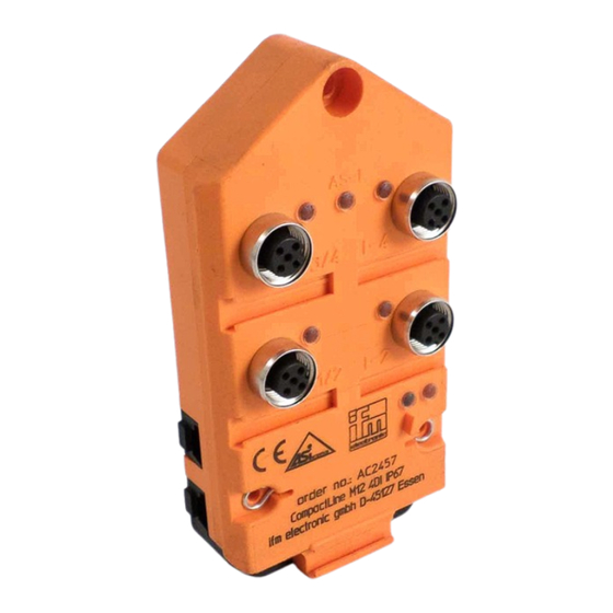
- Seite 1 Montageanleitung Installation Instructions Notice de Montage CompactLine Modul IR CompactLine module IR Module CompactLine IR AC2457...
-
Seite 2: Bestimmungsgemäße Verwendung
Bestimmungsgemäße Verwendung • maximale Anzahl von Modulen pro Master: 31 (62 mit AS-i Master 2.1) • AS-Interface Version 2.1 • erweiterter Adressmode möglich • AS-i Profil: S-0.A.E Adressieren Auslieferungsadresse ist 0. Adressieren mit den Adressiergeräten AC 1143 oder AC1144 Das Modul kann über die Adressieradapter E70123 oder E70211 adressiert werden. -
Seite 3: Pinbelegung Der Eingänge
Pinbelegung der Eingänge Eingänge M12-Buchse I-1/2 I-3/4 Sensorversorgung L+ Sensorversorgung L- Datenbit Eingang Buchse I-1/2 I-1/2 I-2 I-3/4 I-3/4 I-4 Betrieb Prüfen Sie, ob das Gerät sicher funktioniert. Anzeige durch LEDs: • LED 1 gelb: Eingang geschaltet • LED 2 grün: AS-i Spannungsversorgung o.k. -
Seite 4: Wartung
Montage Schalten Sie während der Montage die Anlage spannungsfrei. Wählen Sie eine plane Montagefläche. Das Modul muß mit der gesamten Bodenfläche auf der Montagefläche aufliegen. 1. Befestigen Unterteil Montagefläche (Montagelöcher ; Montageschrauben nicht im Lieferumfang). 2. Legen Sie das AS-i-Standardkabel (gelb) ein. Passen Sie die Kabel richtig in die Profilnut ein. - Seite 5 Falls erforderlich kann das Modul über die Erdungsfedern (1*) geerdet werden. AC2457 Unterteil mit Profilnuten AS-i für Flachkabel LEDs 1 LED 2 AS-i 1* Erdungsfedern LED 3 Fixierung IR-Adapter SEITE...
-
Seite 6: Function And Features
Function and features • maximum number of modules per master: 31 (62 with AS-i master 2.1) • AS-interface version 2.1 • extended addressing mode possible • AS-i profile: S-0.A.E Addressing At the factory the address is set to 0. Addressing with the addressing units AC1143 or AC1144 The module can be addressed via the addressing adapters E70123 or E70211. - Seite 7 Pin connection of the inputs inputs socket M12 I-1/2 I-3/4 sensor supply L+ sensor supply L- Data bit Input Socket I-1/2 I-1/2 I-2 I-3/4 I-3/4 I-4 Operation Check the safe functioning of the unit. Display by LEDs: • LED 1 yellow: input switched •...
-
Seite 8: Technical Data
Installation Disconnect the installation from power before mounting. Select a plane mounting surface. The bottom of the module must lie flat on the mounting surface. 1. Screw the lower part onto the mounting surface (mounting holes mounting screws not supplied). 2. - Seite 9 If required, you can ground the module via the earth springs (1*). AC2457 lower part with profiled AS-i slots for flat cable LEDs 1 LED 2 AS-i 1* earth springs LED 3 fixture infrared adapter PAGE...
-
Seite 10: Fonctionnement Et Caractéristiques
Fonctionnement et caractéristiques • nombre maximal de modules par maître: 31 (62 avec maître AS-i 2.1) • version AS-interface 2.1 • mode d'adressage étendu possible • profil AS-i: S-0.A.E Adressage A la livraison, l'adresse est 0. Adressage avec l'unité d'adressage AC1143 ou AC1144 Le module peut être adressé... - Seite 11 Raccordement des broches entrées entrées prise M12 broche I-1/2 I-3/4 alimentation capteur L+ alimentation capteur L- Bit de données entrée prise I-1/2 I-1/2 I-2 I-3/4 I-3/4 I-4 Fonctionnement Vérifier le bon fonctionnement de l'appareil. Affichage par LED: • LED 1 jaune: entrée commutées •...
-
Seite 12: Données Techniques
Montage Mettre l'installation hors tension avant le montage. Choisir une surface de montage plane afin que le dessous du module soit entièrement en contact. 1. Visser la partie inférieure sur la surface de montage (trous de mon- tage , vis de montage non fournies). 2. - Seite 13 Si nécessaire vous pouvez mettre le module à la terre par les ressorts intégrés aux trous de montage (1*). AC2457 AS-i partie inférieure avec guide profilé pour câble plat LEDs 1 LED 2 AS-i 1* ressorts de mise à la terre LED 3 fixation cordon d'adressage PAGE...