Herunterladen Diese Seite drucken

Werbung

Verfügbare Sprachen

Verfügbare Sprachen

Montageanleitung
Installation instructions
Notice de montage
AS-i Modul
AS-i module
Module AS-i
AC2506

Werbung

loading

Inhaltszusammenfassung für IFM Electronic ASinterfoce AC2506

  • Seite 1 Montageanleitung Installation instructions Notice de montage AS-i Modul AS-i module Module AS-i AC2506...
  • Seite 2 
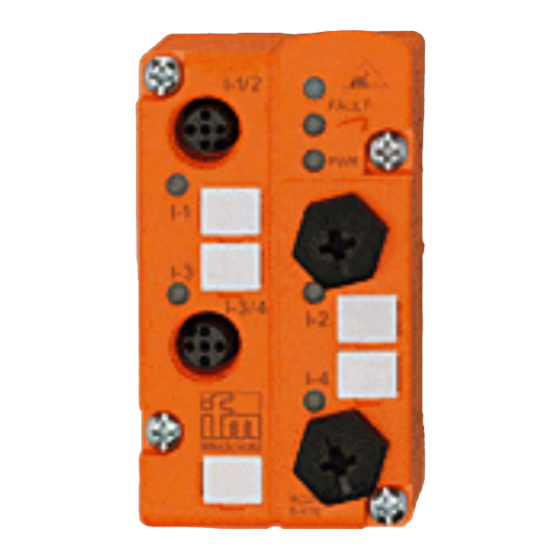
Bestimmungsgemäße Verwendung • AS-i-Profil S-0.1.E • maximale Anzahl von Modulen pro Master: 31 • AS-Interface Version 2.1 Bedien- und Anzeigeelemente LEDs Fixierung für IR-Adapter Beschriftungsfelder 2 Buchsen M12 Montage Montieren Sie das Modul auf ein verdrahtetes Modul-Unterteil des AS-i Netzes, Anzugsdrehmoment 0,8Nm. Technische Daten Sie können das Datenblatt bei Bedarf unter der Internetadresse www.ifm-electronic.com herunterladen.
  • Seite 3 LED3 Infrarot-Empfänger LED2 rot FAULT Fixierung IR-Adapter Eingänge 2 Buchsen M12 LED grün 4x LED1 gelb Spannungs- versorgung M12-Buchse Sensorversorgung L+ Sensorversorgung L- Belegung der Datenbits Datenbit Eingang Buchse I-1/2 I-1/2 I-3/4 I-3/4 Adressieren Vergeben Sie eine freie Adresse zwischen 1 und 31, Auslieferungs- adresse ist 0.
  • Seite 4 Infrarot-Adressierung Das AS-i Modul bietet zusätzlich die Möglichkeit zur Infrarot-Adressie- rung mit dem Adressiergerät AC1144. Die AS-i Kommunikation (gelbes Kabel) muß während der Infra- rot-Adressierung abgeschaltet sein. Klemmen Sie dafür den Master ab. Versorgen Sie die Slaves über das AS-i Netzteil mit Spannung. Die Adressierung erfolgt über das IR-Adressierkabel E70211.
  • Seite 5 Function and features • AS-i profile: S-0.1.E • maximum number of modules per master: 31 • AS-interface version 2.1 Operating and display elements LEDs fixture infrared adapter labels 2 sockets M12 Mounting Mount the module onto the wired module lower part of the AS-i net- work, tightening torque 0.8Nm.
  • Seite 6 LED3 infrared reciever LED2 red FAULT fixture infrared 2 sockets M12 inputs adapter 4x LED1 yellow LED green PWR sensor supply o.k socket M12 sensor supply L+ sensor supply L- Data bits Data bit Input Socket I-1/2 I-1/2 I-3/4 I-3/4 Addressing Assign a free address between 1 and 31.
  • Seite 7 Infrared addressing The AS-i module also offers the option of infrared addressing with the addressing unit AC1144. The AS-i communication (yellow cable) must be switched off during the infrared addressing. To do so, disconnect the master. Supply the slaves with voltage via the AS-i power supply. Addressing is carried out via the IR addressing cable E70211.
  • Seite 8 Fonctionnement et caractéristiques • Profil AS-i S-0.1.E • nombre maximal de modules par maître: 31 • version AS-interface 2.1 Eléments de service et d’indication fixation adaptateur infrarouge étiquettes 2 prises M12 Montage Monter le module sur l'embase de câblage rac-cordé au réseau AS-i, couple de serrage 0,8Nm.
  • Seite 9 LED2 rouge LED3 récepteur infrarouge FAULT entrées fixation adaptateur 2 prises M12 infrarouge 4x LED1 jaunes LED verte PWR alimentation capteur o.k prise M12 broche alimentation capteur L+ alimentation capteur L- Affectation des bits de données Bit de données Entrée Prise I-1/2 I-1/2...
  • Seite 10 Adressage infrarouge Le module AS-i offre également l'option d'adressage infrarouge par l’unité d'adressage AC1144. La communication AS-i (câble jaune) doit être désactivée pen- dant l'adressage infrarouge. Pour ce faire, débrancher le maître. Alimenter les esclaves en tension avec le bloc d'alimentation AS-i. L'adressage s'effectue via le cordon d'adressage infrarouge E70211.