Herunterladen Diese Seite drucken

Werbung

Verfügbare Sprachen

Verfügbare Sprachen

Montageanleitung
Installation instructions
Notice de montage
AS-i Modul
AS-i module
Module AS-i
AC2515
AC2565

Werbung

loading

Inhaltszusammenfassung für IFM Electronic AC2515

  • Seite 1 Montageanleitung Installation instructions Notice de montage AS-i Modul AS-i module Module AS-i AC2515 AC2565...
  • Seite 2 
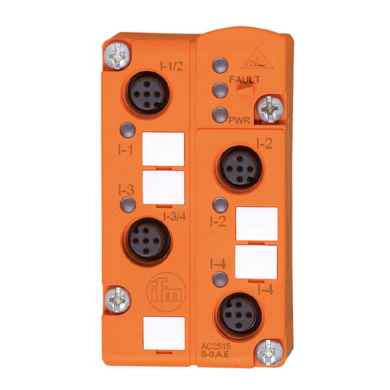
Bestimmungsgemäße Verwendung • AS-i-Profil S-0.A.E • maximale Anzahl von Modulen pro Master: 31 (62 mit AS-i Master 2.1) • AS-Interface Version 2.1 • Besonderheit AC2565: Edelstahlschrauben, Viton-Dichtung Bedien- und Anzeigeelemente LEDs Fixierung für IR-Adapter 4 Buchsen M12 Beschriftungsfelder Montage Montieren Sie das Modul auf ein verdrahtetes Modul-Unterteil des AS-i Netzes, Anzugsdrehmoment 0,8 Nm.
  • Seite 3 Eingänge LED3 Infrarot-Empfänger LED2 rot FAULT I-1/2 I-3/4 4x LED1 Fixierung gelb IR-Adapter LED grün Spannungs- versorgung M12-Buchse 4 Buchsen Sensorversorgung L+ Sensorversorgung L- Datenbit Eingang Buchse I-1/2 I-1/2 I-2 I-3/4 I-3/4 I-4 Adressieren mit dem Adressiergerät AC1144 Das Modul kann in Verbindung mit dem FK-Unterteil AC5010 (mit Adressierbuchse) über das Adressierkabel (E70213) in montiertem und verdrahtetem Zustand adressiert werden.
  • Seite 4 Die AS-i Kommunikation (gelbes Kabel) muss während der Infrarot- Adressierung abgeschaltet sein. Klemmen Sie dafür den Master ab. Versorgen Sie die Slaves über das AS-i Netzteil mit Spannung. Die Adressierung erfolgt über das IR-Adressierkabel E70211. Bei Verwendung von ifm AS-i Netzteilen SL kann die Kommunikation über einen Stecker am Netzteil deaktiviert werden.
  • Seite 5 Function and features • AS-i profile: S-0.A.E • maximum number of modules per master: 31 (62 with AS-i master 2.1) • AS-interface version 2.1 • special features AC2565: stainless steel screws, Viton sealing Operating and display elements LEDs fixture infrared adapter 4 sockets M12 labels Mounting...
  • Seite 6 inputs LED3 infrared reciever LED2 red FAULT I-1/2 I-3/4 4x LED1 fixture yellow infrared adapter LED green PWR sensor supply o.k socket M12 4 sockets sensor supply L+ sensor supply L- Data bit Input Socket I-1/2 I-1/2 I-2 I-3/4 I-3/4 I-4 Addressing with the addressing unit AC1144 If the mounted and wired module is used with the FC lower part AC5010 (with addressing socket), it can be addressed via the address-...
  • Seite 7 The AS-i communication (yellow cable) must be switched off during the infrared addressing. To do so, disconnect the master. Supply the slaves with voltage via the AS-i power supply. Addressing is carried out via the IR addressing cable E70211. When the ifm AS-i power supplies SL are used the communication can be deactivated via a plug on the power supply.
  • Seite 8 Fonctionnement et caractéristiques • Profil AS-i S-0.A.E • nombre maximal de modules par maître: 31 (62 avec maître AS-i 2.1) • version AS-interface 2.1 • particularité AC2565 : vis en acier inox, joint en Viton Eléments de service et d’indication LEDs fixation adaptateur infrarouge 4 prises M12...
  • Seite 9 entrées LED3 récepteur infrarouge LED2 rouge FAULT I-1/2 I-3/4 4x LED1 fixation jaunes adaptateur infrarouge LED verte alimentation capteur o.k prise M12 broche 4 prises alimentation capteur L+ alimentation capteur L- Bit de données entrée prise I-1/2 I-1/2 I-2 I-3/4 I-3/4 I-4 Adressage avec l'unité...
  • Seite 10 La communication AS-i (câble jaune) doit être désactivée pendant l'adressage infrarouge. Pour ce faire, débrancher le maître. Alimenter les esclaves en tension avec le bloc d'alimentation AS-i. L'adressage s'effectue via le cordon d'adressage infrarouge E70211. Lorsque des blocs d'alimentation ifm AS-i SL sont utilisés, la communi- cation peut être désactivée par un connecteur sur le bloc d'alimenta- tion.

Diese Anleitung auch für:

Ac2565