Herunterladen Inhalt Inhalt Diese Seite drucken
SICK MOC3ZA Betriebsanleitung
Vorschau ausblenden Andere Handbücher für MOC3ZA:
Inhaltsverzeichnis

Werbung

Verfügbare Sprachen

Verfügbare Sprachen

O P E R A T I N G I N S T R U C T I O N S
Standstill Monitor MOC3ZA
Standstill monitor
de
en
fr

Werbung

Inhaltsverzeichnis
loading

Inhaltszusammenfassung für SICK MOC3ZA

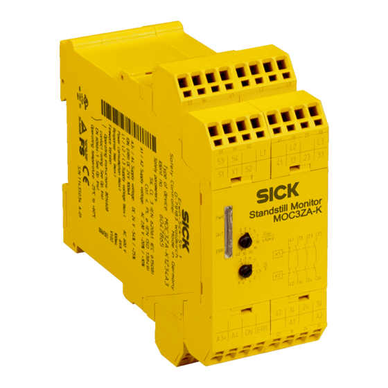
  • Seite 1 O P E R A T I N G I N S T R U C T I O N S Standstill Monitor MOC3ZA Standstill monitor...
  • Seite 2 Page 81–119 This document is protected by the law of copyright, whereby all rights established therein remain with the company SICK AG. Reproduction of this document or parts of this document is only permissible within the limits of the legal determination of Copyright Law. Alteration or abridgement of the document is not permitted without the explicit written approval of the company SICK AG.
  • Seite 3: Inhaltsverzeichnis

    Inbetriebnahme ....................... 25 Prüfhinweise ......................27 7.2.1 Prüfungen vor der Erstinbetriebnahme..........27 7.2.2 Regelmäßige Prüfung der Schutzeinrichtung durch befähigte Personen ....................27 8014608/1C43/2021- 08- 12 © SICK AG • Industrial Safety Systems • Deutschland • Alle Rechte vorbehalten Irrtümer und Änderungen vorbehalten...
  • Seite 4 11 Anhang........................... 40 11.1 Konformität mit EU-Richtlinien................40 11.2 Checkliste für den Hersteller................. 41 11.3 Tabellenverzeichnis ....................42 11.4 Abbildungsverzeichnis.................... 42 © SICK AG • Industrial Safety Systems • Deutschland • Alle Rechte vorbehalten 8014608/1C43/2021- 08- 12 Irrtümer und Änderungen vorbehalten...
  • Seite 5: Zu Diesem Dokument

    Diese Betriebsanleitung richtet sich an die Planer, Entwickler und Betreiber von Anlagen, welche durch einen oder mehrere Standstill Monitore MOC3ZA abgesichert werden sollen. Sie richtet sich auch an Personen, die den MOC3ZA in eine Maschine integrieren, erstmals in Betrieb nehmen oder warten.
  • Seite 6: Verwendete Abkürzungen

    Gefahr bringende Zustände geben:  Maschinenbewegungen  Strom führende Teile  Sichtbare oder unsichtbare Strahlung  Eine Kombination mehrerer Gefahren  usw. © SICK AG • Industrial Safety Systems • Deutschland • Alle Rechte vorbehalten 8014608/1C43/2021- 08- 12 Irrtümer und Änderungen vorbehalten...
  • Seite 7: Zur Sicherheit

    MOC3ZA Zur Sicherheit Dieses Kapitel dient Ihrer Sicherheit und der Sicherheit der Anlagenbenutzer. ➢ Bitte lesen Sie dieses Kapitel sorgfältig, bevor Sie mit dem Standstill Monitor MOC3ZA oder der durch den MOC3ZA geschützten Maschine arbeiten. Befähigte Personen Der Standstill Monitor MOC3ZA darf nur von befähigten Personen montiert und in Betrieb genommen werden.
  • Seite 8: Allgemeine Sicherheitshinweise Und Schutzmaßnahmen

    Anspruch auf Gewährleistung verfällt.  Beschädigte Geräte dürfen nicht in Betrieb genommen werden.  Beachten Sie bei Montage, Installation und Anwendung des MOC3ZA die in Ihrem Land gültigen Normen und Richtlinien.  Für Einbau und Verwendung des MOC3ZA sowie für die Inbetriebnahme und wieder- kehrende technische Überprüfung gelten die nationalen und internationalen Rechts-...
  • Seite 9: Umweltgerechtes Verhalten

    MOC3ZA Umweltgerechtes Verhalten Der Standstill Monitor MOC3ZA ist so konstruiert, dass er die Umwelt so wenig wie möglich belastet. Er verbraucht nur ein Minimum an Energie und Ressourcen. ➢ Handeln Sie auch am Arbeitsplatz immer mit Rücksicht auf die Umwelt.
  • Seite 10: Produktbeschreibung

    Betrieb nehmen.  Berücksichtigen Sie immer die Sicherheit der gesamten Anlage! Der MOC3ZA ist geeignet, um als Teil einer Anlage oder Maschine sicherheitsbezogene Funktionen zu übernehmen. In eine solche Anlage sind in der Regel weitere Geräte und ACHTUNG Komponenten eingebunden. Es liegt in der Verantwortung des Herstellers der Anlage, durch korrekte Auswahl, Montage, Verdrahtung, Einstellung und Betrieb der Komponenten die sicherheitsbezogene Gesamtfunktion zu gewährleisten.
  • Seite 11: Bedien- Und Anzeigeelemente

    MOC3ZA Achten Sie immer auf eine sichere Einstellung des MOC3ZA im Rahmen Ihrer Anwendung! Sie sind für die korrekte Einstellung des MOC3ZA in Bezug auf die Spannungsschwelle U und Stillstandszeit t verantwortlich. Die korrekte Einstellung muss durch entsprechende Tests unter Worst-Case-Bedingungen ermittelt werden.
  • Seite 12: Tab. 2: Bedeutung Der Betriebsanzeigen Des Moc3Za

    Drehschalter U Einstellung der Spannungsschwelle (U ) zur Stillstandserkennung Drehschalter t Einstellung der Stillstandszeit (t ) bis zur Freigabe der Sicherheitskontakte © SICK AG • Industrial Safety Systems • Deutschland • Alle Rechte vorbehalten 8014608/1C43/2021- 08- 12 Irrtümer und Änderungen vorbehalten...
  • Seite 13: Klemmen-Belegung

    Die Meldekontakte 53/54 sowie die Ausgänge ON und ERR dienen nur zu Meldezwecken und dürfen nicht für Sicherheitsstromkreise verwendet werden! ACHTUNG 3.3.1 Anschlussschema Abb. 2: Anschlussschema des Standstill Monitors MOC3ZA 8014608/1C43/2021- 08- 12 © SICK AG • Industrial Safety Systems • Deutschland • Alle Rechte vorbehalten Irrtümer und Änderungen vorbehalten...
  • Seite 14: Funktion Des Standstill Monitors Moc3Za

    Öffnerkontakte 41/42 schließen). Das Melderelais fällt ab (Meldekontakte 53/54 öffnen), der Halbleiterausgang ON schaltet aus und die LED OUT leuchtet  Gelb (U überschrit- ten). Abb. 3: Funktionsdiagramm MOC3ZA © SICK AG • Industrial Safety Systems • Deutschland • Alle Rechte vorbehalten 8014608/1C43/2021- 08- 12 Irrtümer und Änderungen vorbehalten...
  • Seite 15: Schützkontrolle (Edm)

    Standstill Monitors MOC3ZA nicht gewährleistet (siehe Kapitel 5 „Elektroinstallation“ auf Seite 20). Wenn keine Schützkontrolle (EDM) benötigt wird, dann müssen die Klemmen S1/X1 überbrückt werden. 8014608/1C43/2021- 08- 12 © SICK AG • Industrial Safety Systems • Deutschland • Alle Rechte vorbehalten Irrtümer und Änderungen vorbehalten...
  • Seite 16: Betrieb Mit Gleichstrommotoren

    Hinweise  Da die Remanenzspannung bei Gleichstrommotoren in aller Regel ein Gleichspannungs- signal ist, meldet der MOC3ZA bei Betrieb und Auslauf ständig einen Offset- oder Ader- bruchfehler an der LED ERR und am Halbleiterausgang ERR.  Alle anderen Funktionen sind nicht beeinträchtigt.
  • Seite 17 Umschaltungen beendet sind, sollte die Fehlerspeicherung durch Überbrücken der Klemmen S2/X1 deaktiviert sein (siehe Abschnitt 8.3.5 „Fehlerspeicherung und -löschung“ auf Seite 30). 8014608/1C43/2021- 08- 12 © SICK AG • Industrial Safety Systems • Deutschland • Alle Rechte vorbehalten Irrtümer und Änderungen vorbehalten...
  • Seite 18: Montage

     Steckbare Klemmenblöcke mit Schraubklemmen Siehe auch Abschnitt 9.1 „Datenblatt“ auf Seite 33. Abb. 4: Anschlussoptionen mit steckbaren Klemmen- blöcken © SICK AG • Industrial Safety Systems • Deutschland • Alle Rechte vorbehalten 8014608/1C43/2021- 08- 12 Irrtümer und Änderungen vorbehalten...
  • Seite 19: Demontage Der Steckbaren Klemmenblöcke

    Stellen Sie sicher, dass abgezogene Klemmenblöcke nur auf dem richtigen Steckplatz ACHTUNG wieder aufgesteckt werden. Bringen Sie dazu z.B. eindeutige Beschriftungen an den Klemmenblöcken an. 8014608/1C43/2021- 08- 12 © SICK AG • Industrial Safety Systems • Deutschland • Alle Rechte vorbehalten Irrtümer und Änderungen vorbehalten...
  • Seite 20: Elektroinstallation

    Hinweise  Beachten Sie die Hinweise und Vorschriften in Kapitel 4 „Montage“ auf Seite 18.  Der Standstill Monitor MOC3ZA ist gemäß den Beispielen in Kapitel 6 „Applikations- und Schaltungsbeispiele“ auf Seite 22 zu verdrahten. Der Anschluss von Gleichstrom- motoren erfolgt wie bei einphasigen Wechselstrommotoren.
  • Seite 21 Wenn z.B. die Klemme S2 von einer SPS über ein Koppelrelais angesteuert werden soll, so muss dieses je nach Höhe der maximalen Messeingangsspannung (Motorspannung) über eine entsprechende sichere Trennung verfügen. 8014608/1C43/2021- 08- 12 © SICK AG • Industrial Safety Systems • Deutschland • Alle Rechte vorbehalten Irrtümer und Änderungen vorbehalten...
  • Seite 22: Applikations- Und Sc

    MOC3ZA mit dreiphasigem Motor Motorschütz Anschluss des MOC3ZA mit einem einphasigen Motor/DC-Motor Abb. 7: Schaltungsbeispiel MOC3ZA mit einem einphasi- gen Motor/DC-Motor © SICK AG • Industrial Safety Systems • Deutschland • Alle Rechte vorbehalten 8014608/1C43/2021- 08- 12 Irrtümer und Änderungen vorbehalten...
  • Seite 23: Abb. 8: Schaltungsbeispiel Schutztürentriegelung Mit Stillstandserkennung

    Stillstandserkennung i10 P i10 Lock Entriegelung Stillstand Stern-Dreieck-Schaltung mit Zeitrelais und MOC3ZA Abb. 9: Schaltungsbeispiel Stern-Dreieck-Schaltung mit Zeitrelais und MOC3ZA 8014608/1C43/2021- 08- 12 © SICK AG • Industrial Safety Systems • Deutschland • Alle Rechte vorbehalten Irrtümer und Änderungen vorbehalten...
  • Seite 24 Applikations- und Sc Kapitel 6 Betriebsanleitung MOC3ZA Hauptschalter © SICK AG • Industrial Safety Systems • Deutschland • Alle Rechte vorbehalten 8014608/1C43/2021- 08- 12 Irrtümer und Änderungen vorbehalten...
  • Seite 25: Inbetriebnahme Und Prüfhinweise

    Inbetriebnahme  Keine Inbetriebnahme ohne Prüfung durch eine befähigte Person! Bevor Sie eine durch den Standstill Monitor MOC3ZA geschützte Anlage erstmalig in Betrieb nehmen, muss diese durch eine befähigte Person überprüft und freigegeben ACHTUNG werden. Beachten Sie hierzu die Hinweise in Kapitel „Zur Sicherheit“ auf Seite 7.
  • Seite 26 Werte für U und t ➢ Sichern Sie die eingestellten Werte für U und t gegen Manipulation, z.B. durch einen abgeschlossenen Schaltschrank. © SICK AG • Industrial Safety Systems • Deutschland • Alle Rechte vorbehalten 8014608/1C43/2021- 08- 12 Irrtümer und Änderungen vorbehalten...
  • Seite 27: Prüfhinweise

    ➢ Prüfen Sie, ob die eingestellten Werte für U und t noch mit den bei der Inbetrieb- nahme ermittelten und dokumentierten Werten identisch sind. ➢ Prüfen Sie, ob der MOC3ZA erst nach Ablauf der von Ihnen festgelegten und dokumen- tierten Zeit t den Ausgangskreis freischaltet. 8014608/1C43/2021- 08- 12 ©...
  • Seite 28: Fehlerdiagnose

    ACHTUNG Vollständiger Funktionstest nach Fehlerbeseitigung! ➢ Prüfen Sie, ob der Standstill Monitor MOC3ZA erst nach Ablauf der von Ihnen festgelegten und dokumentierten Zeit t schaltet. ➢ Führen Sie nach der Beseitigung eines Fehlers einen vollständigen Funktionstest durch.
  • Seite 29: Interne Fehler

    Die Fehlermeldung für EDM-Fehler kann entweder gespeichert oder nach Fehlerbehebung automatisch zurückgesetzt werden (siehe Abschnitt 8.3.5 „Fehlerspeicherung und - löschung“ auf Seite 30). 8014608/1C43/2021- 08- 12 © SICK AG • Industrial Safety Systems • Deutschland • Alle Rechte vorbehalten Irrtümer und Änderungen vorbehalten...
  • Seite 30: Gleichzeitigkeit Der Messsignale

    Dieser Abschnitt behandelt mögliche Fehler und wie Sie darauf reagieren können. Eine Beschreibung der LEDs finden Sie in Abschnitt 3.2 „Bedien- und Anzeigeelemente“ auf Seite 11. Tab. 5: Fehlerbehebung © SICK AG • Industrial Safety Systems • Deutschland • Alle Rechte vorbehalten 8014608/1C43/2021- 08- 12 Irrtümer und Änderungen vorbehalten...
  • Seite 31 Wenn der Gleichzeitigkeitsfehler bestehen bleibt: ➢ Überprüfen Sie die Verdrahtung der Messeingänge L1/L2/L3. Siehe auch Abschnitt 8.3.4 „Gleichzeitigkeit der Messsignale“ auf Seite 30. 8014608/1C43/2021- 08- 12 © SICK AG • Industrial Safety Systems • Deutschland • Alle Rechte vorbehalten Irrtümer und Änderungen vorbehalten...
  • Seite 32 -löschung“ auf Seite 30). Dies gilt auch bei Verwendung von elektronischen Motorstellgliedern, wenn diese z.B. in der Bremsphase eine Gleichspannung erzeugen. © SICK AG • Industrial Safety Systems • Deutschland • Alle Rechte vorbehalten 8014608/1C43/2021- 08- 12 Irrtümer und Änderungen vorbehalten...
  • Seite 33: Technische Daten

    Um die Anforderungen der relevanten Produktnormen (z. B . IEC 61496-1) zu erfüllen, muss die externe Span- nungsversorgung der Geräte u.a. einen Netzausfall von 20 ms überbrücken können. Geeignete Netzteile sind bei SICK als Zubehör erhältlich. 8014608/1C43/2021- 08- 12 © SICK AG • Industrial Safety Systems • Deutschland • Alle Rechte vorbehalten Irrtümer und Änderungen vorbehalten...
  • Seite 34 (ON, ERR) = 100 mA (kurzschlussfest) ON für Freigabe, ERR für Fehler Meldekontakte 53/54 (Schließer) 3 A/250 V AC G.P. © SICK AG • Industrial Safety Systems • Deutschland • Alle Rechte vorbehalten 8014608/1C43/2021- 08- 12 Irrtümer und Änderungen vorbehalten...
  • Seite 35 Amplitude 0,35 mm 10 … 55 Hz (EN 60068-2-6) Klimafestigkeit 25/060/04 (EN 60068-1) Leiteranschlüsse DIN 46228-1/-2/-3/-4 Nur für UL-508-Anwendungen Nur 60 °C-Kupferlitzen 8014608/1C43/2021- 08- 12 © SICK AG • Industrial Safety Systems • Deutschland • Alle Rechte vorbehalten Irrtümer und Änderungen vorbehalten...
  • Seite 36 Schnellbefestigung Hutschiene (EN 60715) Nettogewicht Ca. 400 g Geräteabmessungen (B × H × T) 45 × 90 × 121 mm © SICK AG • Industrial Safety Systems • Deutschland • Alle Rechte vorbehalten 8014608/1C43/2021- 08- 12 Irrtümer und Änderungen vorbehalten...
  • Seite 37: Abb. 11: Derating-Kurve Der Kontaktströme Der Sicherheitskontakte

    Für detaillierte Informationen zur Sicherheitsauslegung Ihrer Maschine oder Anlage setzen Sie sich bitte mit Ihrer zuständigen SICK-Niederlassung in Verbindung. 8014608/1C43/2021- 08- 12 © SICK AG • Industrial Safety Systems • Deutschland • Alle Rechte vorbehalten Irrtümer und Änderungen vorbehalten...
  • Seite 38: Maßbild Standstill Monitor Moc3Za

    (2² + 2² + 2² = 12 A²) Maßbild Standstill Monitor MOC3ZA Abb. 12: Maßbild Standstill Monitor MOC3ZA (mm) Hutschiene EN 60  7 15 © SICK AG • Industrial Safety Systems • Deutschland • Alle Rechte vorbehalten 8014608/1C43/2021- 08- 12 Irrtümer und Änderungen vorbehalten...
  • Seite 39: Bestelldaten

    6047865 Versorgungsspannung 230 V AC, mit steckbaren Zugfederklemmen MOC3ZA-KAZ34A6 Standstill Monitor MOC3ZA, 6047864 Versorgungsspannung 400 V AC, mit steckbaren Zugfederklemmen 8014608/1C43/2021- 08- 12 © SICK AG • Industrial Safety Systems • Deutschland • Alle Rechte vorbehalten Irrtümer und Änderungen vorbehalten...
  • Seite 40: Anhang

    (einschließlich aller zutreffenden Änderungen) ist, und dass die entsprechenden Normen und/oder technischen Spezifikationen zugrunde gelegt sind. Vollständige EU-Konformitätserklärung zum Download: www.sick.com © SICK AG • Industrial Safety Systems • Deutschland • Alle Rechte vorbehalten 8014608/1C43/2021- 08- 12 Irrtümer und Änderungen vorbehalten...
  • Seite 41: 11.2 Checkliste Für Den Hersteller

    8. Ist die Schutzfunktion gemäß den Prüfhinweisen dieser Dokumentation überprüft? Nein Diese Checkliste ersetzt nicht die erstmalige Inbetriebnahme sowie regelmäßige Prüfung durch eine befähigte Person. 8014608/1C43/2021- 08- 12 © SICK AG • Industrial Safety Systems • Deutschland • Alle Rechte vorbehalten Irrtümer und Änderungen vorbehalten...
  • Seite 42: Tabellenverzeichnis

    Abb. 10: Fehlercodes der LED ERR in Prioritätsreihenfolge..........28 Abb. 11: Derating-Kurve der Kontaktströme der Sicherheitskontakte ........ 37 Abb. 12: Maßbild Standstill Monitor MOC3ZA (mm) .............. 38 © SICK AG • Industrial Safety Systems • Deutschland • Alle Rechte vorbehalten 8014608/1C43/2021- 08- 12 Irrtümer und Änderungen vorbehalten...
  • Seite 43 EDM error ....................68 8.3.4 Simultaneity of the measured signals ..........69 8.3.5 Error storage and deletion ..............69 8014608/1C43/2021- 08- 12 © SICK AG • Industrial Safety Systems • Germany • All rights reserved Subject to change without notice...
  • Seite 44 11.2 Checklist for the manufacturer ................79 11.3 List of tables ......................80 11.4 List of illustrations ....................80 © SICK AG • Industrial Safety Systems • Germany • All rights reserved 8014608/1C43/2021- 08- 12 Subject to change without notice...
  • Seite 45: About This Document

    Standstill Monitor MOC3ZA. These operating instructions do not provide instructions for operating machines on which the MOC3ZA is, or will be, integrated. Information on this is to be found in the operating instructions for the machine. Target group...
  • Seite 46: Abbreviations Used

     electrical conductors  visible or invisible radiation  a combination of several risks and hazards  and so on © SICK AG • Industrial Safety Systems • Germany • All rights reserved 8014608/1C43/2021- 08- 12 Subject to change without notice...
  • Seite 47: On Safety

    On safety This chapter deals with your own safety and the safety of the equipment operators. ➢ Please read this chapter carefully before working with the Standstill Monitor MOC3ZA or with the machine protected by the MOC3ZA. Qualified safety personnel The Standstill Monitor MOC3ZA must be mounted and commissioned only by qualified safety personnel.
  • Seite 48: General Safety Notes And Protective Measures

    – Low Voltage Directive – work safety regulations and safety rules  Manufacturers and owners of the machine on which a MOC3ZA is used are responsible for obtaining and observing all applicable safety regulations and rules.  The notes, in particular the test notes (see chapter 7 “Commissioning and test notes”...
  • Seite 49: Disposal

    Product Housing Plastic recycling Circuit boards, cable, connector and Electronic recycling electrical connecting pieces Packaging Cardboard, paper Paper/cardboard recycling 8014608/1C43/2021- 08- 12 © SICK AG • Industrial Safety Systems • Germany • All rights reserved Subject to change without notice...
  • Seite 50: Product Description

     Always take into consideration the safety of the entire system! The MOC3ZA is suitable for the provision of safety-related functions as part of a system or machine. Further devices and components are generally incorporated in such a system. It...
  • Seite 51: Controls And Status Indicators

    Chapter 3 MOC3ZA The MOC3ZA measures a voltage at the winding terminals of the motor as it coasts down; the voltage is induced by residual magnetism. For this purpose two redundant measurement channels (L2 against L1 and L3 against L1) are used. If the induced voltage...
  • Seite 52: Terminal Assignment

    The signal contacts 53/54 as well as the outputs ON and ERR are only used for signaling purposes and may not be used for safety circuits! WARNING © SICK AG • Industrial Safety Systems • Germany • All rights reserved 8014608/1C43/2021- 08- 12 Subject to change without notice...
  • Seite 53: Connection Example

    This voltage is evaluated redundantly by the Standstill Monitor MOC3ZA. For this purpose the measurement inputs L2 and L3 are used; L1 is a common reference point. If the...
  • Seite 54: External Device Monitoring (Edm)

    WARNING the measurement circuit L1/L2/L3. Otherwise the safe function of the Standstill Monitor MOC3ZA is not ensured (see chapter 5 “Electrical installation” on page 59). If external device monitoring (EDM) is not required, a jumper must be fitted to terminals S1/X1.
  • Seite 55: Operation With Dc Motors

    MOC3ZA Operation with DC motors It is possible to use the Standstill Monitor MOC3ZA for the detection of the standstill of DC motors if the motors generate a remanence voltage as they coast down. ➢ For this purpose connect the measurement input terminals as for a single-phase AC motor.
  • Seite 56: Motors With Switched Windings

    L1/L2/L3 on the Standstill Monitor MOC3ZA must always be connected to the motor windings for the detection of the standstill, otherwise the error message “wire break” will prevent the enable of the outputs.
  • Seite 57: Mounting

     Checking the installation (see section 7.2 “Test notes” on page 66) Mounting the Standstill Monitor MOC3ZA  Mount the MOC3ZA only in a suitable housing! The control cabinet or assembly casing of the MOC3ZA must at least comply with enclosure rating IP 54. WARNING Secure the MOC3ZA against tampering! ➢...
  • Seite 58: Removing The Plug-In Terminal Blocks

    Ensure that removed terminal blocks are only re-connected to the correct slot. For this WARNING purpose apply, e.g., clear labels to the terminal blocks. © SICK AG • Industrial Safety Systems • Germany • All rights reserved 8014608/1C43/2021- 08- 12 Subject to change without notice...
  • Seite 59: Electrical Installation

     Please pay attention to the notes and regulations in chapter 4 “Mounting” on page 57.  The Standstill Monitor MOC3ZA is to be wired as per the examples in chapter 6 “Application examples and connection diagrams” on page 61. DC motors are connected in the same way as single-phase AC motors.
  • Seite 60 If, e.g., the terminal S2 is to be operated by a PLC via coupling relay, this relay must have correspondingly safe isolation to suit the magnitude of the maximum measurement input voltage (motor voltage). © SICK AG • Industrial Safety Systems • Germany • All rights reserved 8014608/1C43/2021- 08- 12 Subject to change without notice...
  • Seite 61: Application Examples And Connection Diagrams

    Connection of the MOC3ZA to a single-phase motor/DC motor Fig. 7: Connection diagram MOC3ZA with a single-phase motor/DC motor 8014608/1C43/2021- 08- 12 © SICK AG • Industrial Safety Systems • Germany • All rights reserved Subject to change without notice...
  • Seite 62: Fig. 8: Connection Diagram Guard Unlocking With Standstill Detection

    Standstill Star-delta circuit with timer relay and MOC3ZA Fig. 9: Connection diagram star-delta circuit with timer relay and MOC3ZA © SICK AG • Industrial Safety Systems • Germany • All rights reserved 8014608/1C43/2021- 08- 12 Subject to change without notice...
  • Seite 63 Application examples Operating instructions Chapter 6 MOC3ZA Main switch 8014608/1C43/2021- 08- 12 © SICK AG • Industrial Safety Systems • Germany • All rights reserved Subject to change without notice...
  • Seite 64: Commissioning And Test Notes

     Commissioning requires a thorough check by qualified safety personnel! Before you operate a system protected by the Standstill Monitor MOC3ZA for the first time, make sure that the system is first checked and released by qualified safety personnel. On WARNING this subject please pay attention to the notes in the chapter “On safety”...
  • Seite 65 ➢ Secure the values set for U and t against tampering, e.g. by means of a locked control cabinet. 8014608/1C43/2021- 08- 12 © SICK AG • Industrial Safety Systems • Germany • All rights reserved Subject to change without notice...
  • Seite 66: Test Notes

    ➢ Check whether the MOC3ZA only enables the output circuit after the time t determined and documented. © SICK AG • Industrial Safety Systems • Germany • All rights reserved...
  • Seite 67: Fault Diagnosis

    WARNING Complete function test after rectification of fault! ➢ Check whether the Standstill Monitor MOC3ZA only switches after the time t determined and documented has elapsed. ➢ After rectifying a fault, perform a complete function test. SICK support If you cannot rectify an error with the help of the information provided in this chapter, please contact your local SICK representative.
  • Seite 68: Internal Errors

    The error message for an EDM error can either be saved or automatically reset after error rectification (see section 8.3.5 “Error storage and deletion” on page 69). © SICK AG • Industrial Safety Systems • Germany • All rights reserved 8014608/1C43/2021- 08- 12...
  • Seite 69: Simultaneity Of The Measured Signals

    This section addresses possible errors and how you can react to them. You will find a description of the LEDs in chapter 3.2 “Controls and status indicators” on page 51. Tab. 5: Error rectification 8014608/1C43/2021- 08- 12 © SICK AG • Industrial Safety Systems • Germany • All rights reserved Subject to change without notice...
  • Seite 70 ➢ For this purpose carry out the following test: If you short circuit the terminals L1/L2/L3 with no power applied to the motor, the OUT LED must extinguish. © SICK AG • Industrial Safety Systems • Germany • All rights reserved 8014608/1C43/2021- 08- 12 Subject to change without notice...
  • Seite 71 DC voltage during the braking phase. 8014608/1C43/2021- 08- 12 © SICK AG • Industrial Safety Systems • Germany • All rights reserved Subject to change without notice...
  • Seite 72: Technical Specifications

    20 ms. Suitable power supplies are available as accessories from SICK. © SICK AG • Industrial Safety Systems • Germany • All rights reserved 8014608/1C43/2021- 08- 12...
  • Seite 73 = 100 mA (short-circuit protected) ON for Release, ERR for Error Signal contacts 53/54 (normally 3 A/250 V AC G.P. open contact) 8014608/1C43/2021- 08- 12 © SICK AG • Industrial Safety Systems • Germany • All rights reserved Subject to change without notice...
  • Seite 74 Climatic resistance 25/060/04 (EN 60068-1) Cable connections DIN 46228-1/-2/-3/-4 For UL 508 applications only 60 °C copper conductors only © SICK AG • Industrial Safety Systems • Germany • All rights reserved 8014608/1C43/2021- 08- 12 Subject to change without notice...
  • Seite 75 Mounting rail (EN 60715) Net weight Approx. 400 g Dimensions (B × H × T) 45 × 90 × 121 mm 8014608/1C43/2021- 08- 12 © SICK AG • Industrial Safety Systems • Germany • All rights reserved Subject to change without notice...
  • Seite 76: Fig. 11: Derating Curve For The Contact Currents On The Safety Contacts

    Fig. 11: Derating curve for the contact currents on the safety contacts For detailed information on the safety design of your machine or system, please contact your local SICK representative. © SICK AG • Industrial Safety Systems • Germany • All rights reserved...
  • Seite 77: Dimensional Drawing Standstill Monitor Moc3Za

    Dimensional drawing Standstill Monitor MOC3ZA Fig. 12: Dimensional drawing Standstill Monitor MOC3ZA (mm) Mounting rail EN 60  7 15 8014608/1C43/2021- 08- 12 © SICK AG • Industrial Safety Systems • Germany • All rights reserved Subject to change without notice...
  • Seite 78: Ordering Information

    230 V AC, with plug-in spring terminals MOC3ZA-KAZ34A6 Standstill Monitor MOC3ZA, 6047864 supply voltage 400 V AC, with plug-in spring terminals © SICK AG • Industrial Safety Systems • Germany • All rights reserved 8014608/1C43/2021- 08- 12 Subject to change without notice...
  • Seite 79: Annex

    8. Has the protective function been checked in compliance with the test notes of this documentation? This checklist does not replace the initial commissioning, nor the regular inspection by qualified safety personnel. 8014608/1C43/2021- 08- 12 © SICK AG • Industrial Safety Systems • Germany • All rights reserved Subject to change without notice...
  • Seite 80: List Of Tables

    Fig. 11: Derating curve for the contact currents on the safety contacts......76 Fig. 12: Dimensional drawing Standstill Monitor MOC3ZA (mm)........77 © SICK AG • Industrial Safety Systems • Germany • All rights reserved 8014608/1C43/2021- 08- 12 Subject to change without notice...
  • Seite 81 Tests et essais préalables à la première mise en service... 105 7.2.2 Un personnel qualifié doit effectuer un test régulier de l’équipement de protection.............. 105 8014608/1C43/2021- 08- 12 © SICK AG • Industrial Safety Systems • Allemagne • Tous droits réservés Sujet à modification sans préavis...
  • Seite 82 Conformité aux directives UE ................118 11.2 Liste de vérifications à l’attention du fabricant ..........118 11.3 Répertoire des tableaux..................119 11.4 Répertoire des figures..................119 © SICK AG • Industrial Safety Systems • Allemagne • Tous droits réservés 8014608/1C43/2021- 08- 12 Sujet à modification sans préavis...
  • Seite 83: A Propos De Ce Manuel

    MOC3ZA. Cette notice d’instructions n’a pas pour but de fournir des instructions quant à la machine dans laquelle le MOC3ZA est ou doit être intégré. C’est la notice d’instructions de la machine qui s’y applique. À qui cette notice s’adresse-t-elle ? Cette notice d’instructions est destinée aux concepteurs, développeurs et exploitants...
  • Seite 84: Abréviations/Sigles Utilisés

     mouvements de la machine,  conducteurs sous tension,  rayonnement visible ou invisible,  une association de plusieurs risques  etc. © SICK AG • Industrial Safety Systems • Allemagne • Tous droits réservés 8014608/1C43/2021- 08- 12 Sujet à modification sans préavis...
  • Seite 85: La Sécurité

    Standstill Monitor MOC3ZA ou la machine protégée par le MOC3ZA. Qualification du personnel Le Standstill Monitor MOC3ZA ne doit être monté et mis en service que par du personnel qualifié. Sont qualifiées les personnes qui :  ont reçu la formation technique appropriée ...
  • Seite 86: Consignes De Sécurité Et Mesures De Protection D'ordre Général

     Il faut s’assurer que le montage, l’installation et l’utilisation du MOC3ZA sont conformes aux normes et à la réglementation du pays d’exploitation.  Pour le montage et l’utilisation du MOC3ZA ainsi que pour son mise en service et les tests réguliers il faut impérativement appliquer les prescriptions légales nationales et internationales.
  • Seite 87: Pour Le Respect De L'environnement

    MOC3ZA Pour le respect de l’environnement Le Standstill Monitor MOC3ZA est construit de manière à présenter un minimum de risque pour l’environnement. Il n’émet ni ne contient de substances toxiques pour l’environne- ment et consomme aussi peu d’énergie que possible.
  • Seite 88: Description Du Produit

    Il faut toujours prendre en compte la sécurité de l’ensemble de l’installation ! Le MOC3ZA est destiné à assurer des fonctions relatives à la sécurité en tant que partie d’une installation ou d’une machine. Dans une telle installation, il y a en règle générale ATTENTION d’autres appareils et composants interconnectés.
  • Seite 89: Touches De Commande Et Affichage

    Dans le cadre de l’utilisation du MOC3ZA, toujours s’assurer que les réglages sont compatibles avec la sécurité ! L’utilisateur est responsable du réglage du MOC3ZA en ce qui concerne le seuil de tension et le délai de vitesse nulle t .
  • Seite 90 Commutateur rotatif t Réglage du délai de vitesse nulle (t ) nécessaire pour autoriser l’activation des contacts de sécurité © SICK AG • Industrial Safety Systems • Allemagne • Tous droits réservés 8014608/1C43/2021- 08- 12 Sujet à modification sans préavis...
  • Seite 91: Affectation Des Bornes

    ! ATTENTION 3.3.1 Schéma de raccordement Fig. 2 : Schéma de raccorde- ment du Standstill Monitor MOC3ZA 8014608/1C43/2021- 08- 12 © SICK AG • Industrial Safety Systems • Allemagne • Tous droits réservés Sujet à modification sans préavis...
  • Seite 92: Fonction Du Standstill Monitor Moc3Za

    (rémanence) une tension induite dont l’amplitude est proportion- nelle au régime du moteur. Cette tension est mesurée de manière redondante par le Standstill Monitor MOC3ZA. À cet effet, il exploite les entrées de mesure L2 et L3, pour lesquelles L1 sert de commun. Lors- que la tension sur les deux voies de mesure franchit le seuil de tension U par défaut, la...
  • Seite 93: Contrôle Des Contacteurs Commandés (Edm)

    être shuntées. Fonctionnement avec les moteurs à courant continu L’utilisation du Standstill Monitor MOC3ZA pour la détection de vitesse nulle de moteurs à courant continu est possible à condition qu’ils produisent une tension de rémanence pen- dant leur phase d’arrêt.
  • Seite 94: Fonctionnement Avec Les Moteurs À Commande Électronique

    Fonctionnement avec les moteurs à commande électronique La mise en œuvre du Standstill Monitor MOC3ZA pour la détection de vitesse nulle com- plet de moteurs à commande électronique (par ex. variateurs à conversion de fréquence, systèmes électronique de freinage) est possible, si ces derniers ne produisent sur leur sortie aucune tension une fois le moteur arrêté...
  • Seite 95 Chapitre 3 MOC3ZA Avec un raccordement triphasé du MOC3ZA, si les enroulements sont commutés et que les interruptions du circuit de mesure engendrées par cette commutation durent plus de 2 s, le Standstill Monitor détecte alors une rupture de conducteur. Afin que ce défaut ne soit pas mis en mémoire, lorsque les commutations sont terminées, la mise en mémoire...
  • Seite 96: Montage

    Montage du Standstill Monitor MOC3ZA  Le MOC3ZA doit être monté dans un boîtier de protection approprié ! L’armoire électrique ou le boîtier de montage pour le MOC3ZA doit satisfaire au minimum à l’indice de protection IP 54. ATTENTION Le MOC3ZA doit être protégé contre les manipulations ! ➢...
  • Seite 97: Démontage Des Borniers Enfichables

    S’assurer que les borniers déconnectés ne puissent être reconnectés qu’à l’emplacement correct. À cet effet, on peut par exemple inscrire des annotations non ambiguës sur les ATTENTION borniers. 8014608/1C43/2021- 08- 12 © SICK AG • Industrial Safety Systems • Allemagne • Tous droits réservés Sujet à modification sans préavis...
  • Seite 98: Installation Électrique

    Remarques  Observer les conseils prodigués chapitre 4 «Montage» page 96.  Le Standstill Monitor MOC3ZA doit être câblé dans le respect des exemples figurant au chapitre 6 «Exemples d’application et de câblage», page 100. Le raccordement de moteurs à courant continu s’effectue comme pour les moteurs à courant alternatif monophasé.
  • Seite 99 ➢ Réduire autant que possible le découplage parasite sur les liaisons des entrées de mesure car dans la négative, le MOC3ZA pourrait dans certains cas ne pas détecter la vitesse nulle.
  • Seite 100: Exemples D'application Et De Câblage

    Disjoncteur de protection du moteur Raccordement du MOC3ZA avec un moteur monophasé/CC Fig. 7 : Exemple de câblage MOC3ZA avec moteur mono- phasé/CC © SICK AG • Industrial Safety Systems • Allemagne • Tous droits réservés 8014608/1C43/2021- 08- 12 Sujet à modification sans préavis...
  • Seite 101 Commutation étoile-triangle avec relais de temporisation et MOC3ZA Fig. 9 : Exemple de câblage commutation étoile-triangle avec relais de temporisation et MOC3ZA 8014608/1C43/2021- 08- 12 © SICK AG • Industrial Safety Systems • Allemagne • Tous droits réservés Sujet à modification sans préavis...
  • Seite 102 Exemples d’application Chapitre 6 Notice d’instructions MOC3ZA Interrupteur principal © SICK AG • Industrial Safety Systems • Allemagne • Tous droits réservés 8014608/1C43/2021- 08- 12 Sujet à modification sans préavis...
  • Seite 103: Mise En Service Et Consignes De Test

    ! Un personnel qualifié doit tester et valider l’installation protégée par un Standstill Monitor ATTENTION MOC3ZA, avant son première mise en service. Observer les conseils prodigués chapitre «La sécurité» page 85. Contrôler la zone dangereuse ! ➢ Avant la mise en service, il faut s’assurer que personne ne se trouve dans la zone dangereuse.
  • Seite 104 ➢ Empêcher la manipulation des valeurs de U et de t , par ex. en utilisant une armoire électrique fermée à clé. © SICK AG • Industrial Safety Systems • Allemagne • Tous droits réservés 8014608/1C43/2021- 08- 12 Sujet à modification sans préavis...
  • Seite 105: Consignes De Test

    ➢ Il est nécessaire de former les opérateurs par le personnel qualifié et avant qu’ils ne prennent leur service sur la machine mise en sécurité au moyen du Standstill Monitor MOC3ZA. La responsabilité de la formation et la documentation écrite échoient à l’ex- ploitant de la machine.
  • Seite 106: Diagnostics Des Défauts

    ATTENTION Effectuer un test complet après l’élimination d’un défaut ! ➢ Contrôler si le Standstill Monitor MOC3ZA commute seulement après écoulement du temps t qui a été déterminé et documenté. ➢ Après élimination d’un défaut, il faut effectuer un test fonctionnel complet.
  • Seite 107: Défauts Internes

    Le message d’erreur pour une défaillance EDM peut soit être mise en mémoire, soit automatiquement réinitialisée après l’élimination du défaut (cf. section 8.3.5 «Mise en mémoire et effacement de défauts», page 108). 8014608/1C43/2021- 08- 12 © SICK AG • Industrial Safety Systems • Allemagne • Tous droits réservés Sujet à modification sans préavis...
  • Seite 108: Simultanéité Des Signaux De Mesure

    LED se trouve section 3.2 «Touches de commande et affichage» page 89. Tab. 5 : Défauts et l’élimina- tion des défauts © SICK AG • Industrial Safety Systems • Allemagne • Tous droits réservés 8014608/1C43/2021- 08- 12 Sujet à modification sans préavis...
  • Seite 109 ➢ Vérifier le câblage des entrées de mesure L1/L2/L3. Voir aussi la section 8.3.4 «Simultanéité des signaux de mesure», page 108. 8014608/1C43/2021- 08- 12 © SICK AG • Industrial Safety Systems • Allemagne • Tous droits réservés Sujet à modification sans préavis...
  • Seite 110 électroniques de contrôle du moteur dans le cas où ceux-ci génèrent une tension continue par ex. pendant la phase de freinage. © SICK AG • Industrial Safety Systems • Allemagne • Tous droits réservés 8014608/1C43/2021- 08- 12 Sujet à modification sans préavis...
  • Seite 111: Caractéristiques Techniques

    20 ms. Des alimentations conformes sont disponibles chez SICK en tant qu’accessoires. 8014608/1C43/2021- 08- 12 © SICK AG • Industrial Safety Systems • Allemagne • Tous droits réservés Sujet à modification sans préavis...
  • Seite 112 = 100 mA (protégées contre les courts-circuits) ON pour autorisation, ERR pour défaut Contacts d’état 53/54 3 A/250 V CA G.P. (contact NO) © SICK AG • Industrial Safety Systems • Allemagne • Tous droits réservés 8014608/1C43/2021- 08- 12 Sujet à modification sans préavis...
  • Seite 113 1 kV (EN 61000-4-5) – HF transmis par le câblage 10 V (EN 61000-4-6) Antiparasitage Seuil classe B (EN 55011) 8014608/1C43/2021- 08- 12 © SICK AG • Industrial Safety Systems • Allemagne • Tous droits réservés Sujet à modification sans préavis...
  • Seite 114 Rail de montage (EN 60 7 15) Poids net Env. 400 g Dimensions (B × H × T) 45 × 90 × 121 mm © SICK AG • Industrial Safety Systems • Allemagne • Tous droits réservés 8014608/1C43/2021- 08- 12 Sujet à modification sans préavis...
  • Seite 115 Pour obtenir des informations détaillées sur la conception de sécurité de la machine ou installation, prendre contact avec l’agence SICK la plus proche. 8014608/1C43/2021- 08- 12 © SICK AG • Industrial Safety Systems • Allemagne • Tous droits réservés Sujet à modification sans préavis...
  • Seite 116: Schéma Coté Standstill Monitor Moc3Za

    Schéma coté Standstill Monitor MOC3ZA Fig. 12 : Schéma coté Stand- still Monitor MOC3ZA (mm) Rail de montage EN 60  7 15 © SICK AG • Industrial Safety Systems • Allemagne • Tous droits réservés 8014608/1C43/2021- 08- 12 Sujet à modification sans préavis...
  • Seite 117: Références

    à ressort enfichables MOC3ZA-KAZ34A6 Standstill Monitor MOC3ZA, 6047864 tension d’alimentation 400 V CA, avec bornes à ressort enfichables 8014608/1C43/2021- 08- 12 © SICK AG • Industrial Safety Systems • Allemagne • Tous droits réservés Sujet à modification sans préavis...
  • Seite 118: Annexe

    Cette liste de vérifications ne dispense en aucune façon de la première mise en service ni de la vérification régulière par un personnel qualifié. © SICK AG • Industrial Safety Systems • Allemagne • Tous droits réservés 8014608/1C43/2021- 08- 12...
  • Seite 119: 11.3 Répertoire Des Tableaux

    Fig. 11 : Courbe de dégradation en fonction du courant des contacts (contacts de sécurité) ........................115 Fig. 12 : Schéma coté Standstill Monitor MOC3ZA (mm) ........... 116 8014608/1C43/2021- 08- 12 © SICK AG • Industrial Safety Systems • Allemagne • Tous droits réservés Sujet à modification sans préavis...

Inhaltsverzeichnis