bürkert 8644 AirLINE Betriebsanleitung
Elektrisches/pneumatisches automatisierungssystem
Vorschau ausblenden
Andere Handbücher für 8644 AirLINE:
- Bedienungsanleitung (134 Seiten) ,
- Schnellstart (58 Seiten) ,
- Betriebsanleitung (34 Seiten)
Inhaltsverzeichnis
Werbung
Verfügbare Sprachen
Verfügbare Sprachen
Quicklinks
All manuals and user guides at all-guides.com
Type 8644 AirLINE
Elektrisches/pneumatisches Automatisierungssystem
Deutsch
unter Verwendung von Phoenix-Elektronikmodulen
English
Remote Process Actuation Control System
using Phoenix electronics modules
Francais
Système d'automatisation électrique / pneumatique
associé à l'utilisation des modules électroniques
Phœnix
F l u i d C o n t r o l S y s t e m s
Werbung
Inhaltsverzeichnis
Fehlerbehebung

Verwandte Anleitungen für bürkert 8644 AirLINE


Inhaltszusammenfassung für bürkert 8644 AirLINE
- Seite 1 All manuals and user guides at all-guides.com Type 8644 AirLINE Elektrisches/pneumatisches Automatisierungssystem Deutsch unter Verwendung von Phoenix-Elektronikmodulen English Remote Process Actuation Control System using Phoenix electronics modules Francais Système d’automatisation électrique / pneumatique associé à l’utilisation des modules électroniques Phœnix...
-
Seite 2: Inhaltsverzeichnis
All manuals and user guides at all-guides.com NHALT Inhaltsverzeichnis der Gesamtbedienungsanleitung Typ 8644 AirLINE Elektrisches und pneumatisches Automatisierungs- system ALLGEMEINE HINWEISE ................AH 1 DARSTELLUNGSMITTEL ..............AH 2 ALLGEMEINE SICHERHEITSHINWEISE ..............AH 2 Schutz gegen Beschädigung durch elektrostatische Aufladung ....... AH 2 Sicherheitshinweise für das Ventil .............. - Seite 3 All manuals and user guides at all-guides.com NHALT BESCHREIBUNG DES GESAMTSYSTEMS BÜRKERT - PHOENIX ..SP 1 AUFBAU DES PHOENIX-INLINE-SYSTEM ............. SP 2 FELDBUSMODUL PROFIBUS-DP-BUSKNOTEN ........... SP 3 Technische Daten des Feldbusknotens Profibus-DP ........SP 4 Schnittstelle (Profibus) ..................SP 5 24-V-Haupteinspeisung/24-V-Segmenteinspeisung.........
- Seite 4 All manuals and user guides at all-guides.com NHALT INSTALLATION....................IN 1 SCHRITTE ZUR INSTALLATION DER VENTILINSEL ..........IN 2 ENTFERNEN DER TRANSPORTSICHERUNG ............IN 3 EINBAU DES AirLINE-SYSTEMS ................IN 4 FLUIDISCHE INSTALLATION ..................IN 5 BESCHRIFTUNG DER ANSCHLÜSSE ..............IN 8 ELEKTRISCHE INSTALLATION ................
- Seite 5 All manuals and user guides at all-guides.com NHALT KONFIGURATION DES PROFIBUS-DP ............. KP 1 ADRESSIERUNG IM PROZESSABBILD (1) ............KP 3 ADRESSIERUNG IM PROZESSABBILD (2) ............KP 3 ADRESSIERUNG IM PROZESSABBILD (3) ............KP 4 MODULE AUS DER GSD-DATEI ................KP 5 EINSTELLUNGEN IN DER GSD-DATEI ..............
-
Seite 6: Allgemeine Hinweise
All manuals and user guides at all-guides.com LLGEMEINE INWEISE ALLGEMEINE HINWEISE DARSTELLUNGSMITTEL ....................AH 2 ALLGEMEINE SICHERHEITSHINWEISE ............... AH 2 Schutz gegen Beschädigung durch elektrostatische Aufladung .............AH 2 Sicherheitshinweise für das Ventil .....................AH 3 LIEFERUMFANG ......................AH 4 GARANTIEBESTIMMUNGEN ..................AH 4 Typ 8644 AH 1... -
Seite 7: Darstellungsmittel
All manuals and user guides at all-guides.com LLGEMEINE INWEISE DARSTELLUNGSMITTEL In dieser Betriebsanleitung werden folgende Darstellungsmittel verwendet: markiert einen Arbeitsschritt, den Sie ausführen müssen ACHTUNG! kennzeichnet Hinweise, bei deren Nichtbeachtung Ihre Gesundheit oder die Funktionsfähigkeit des Gerätes gefährdet ist HINWEIS kennzeichnet wichtige Zusatzinformationen, Tips und Empfehlungen ALLGEMEINE SICHERHEITSHINWEISE Beachten Sie die Hinweise dieser Betriebsanleitung sowie die Einsatzbedingungen und zulässigen Daten... -
Seite 8: Sicherheitshinweise Für Das Ventil
All manuals and user guides at all-guides.com LLGEMEINE INWEISE Sicherheitshinweise für das Ventil ACHTUNG! • Halten Sie sich bei Einsatzplanung und Betrieb des Gerätes an die einschlägigen allgemein anerkannten sicherheitstechnischen Regeln. • Treffen Sie geeignete Maßnahmen, um unbeabsichtigtes Betätigen oder unzulässige Beein- trächtigungen auszuschließen. -
Seite 9: Lieferumfang
All manuals and user guides at all-guides.com LLGEMEINE INWEISE LIEFERUMFANG Überzeugen Sie sich unmittelbar nach Erhalt der Sendung, dass der Inhalt nicht beschädigt ist und mit dem auf dem beigelegten Packzettel angegebenen Lieferumfang übereinstimmt. Bei Unstimmigkeiten wenden Sie sich bitte umgehend an unseren Kundenservice: Bürkert Steuer- und Regelungstechnik Chr.-Bürkert-Str. -
Seite 10: Systembeschreibung Bürkert-Airline-System
All manuals and user guides at all-guides.com AirLINE-S YSTEMBESCHREIBUNG ÜRKERT YSTEM SYSTEM- BESCHREIBUNG BÜRKERT AirLINE-SYSTEM MODULARES ELEKTRISCHES/PNEUMATISCHES AUTOMATISIERUNGSSYSTEM .. SB 2 AUFBAU DES PNEUMATIKBLOCKS ................SB 3 Aufbau der Einspeisungen ........................SB 5 Ventilscheiben ............................. SB 7 Elektronik-Grundmodul 2fach Typ ME02 ....................SB 9 Pneumatik-Grundmodul 2fach Typ MP11.................. -
Seite 11: Modulares Elektrisches/Pneumatisches Automatisierungs- System
MODULARES ELEKTRISCHES/PNEUMATISCHES AUTOMATISIERUNGS- SYSTEM TYP 8644 AirLINE Typ 8644 AirLINE ist ein elektrisches und pneumatisches Automatisierungssystem, das für den Einsatz im Schaltschrank oder Schaltkasten optimiert wurde. In einem durchgängigen System sind alle elektro- nischen und pneumatischen Komponenten vereinheitlicht, so dass unter Beachtung einfacher Regeln pneumatische, elektrische und elektronische Module unterschiedlicher Funktionalität sehr einfach mitein-... -
Seite 12: Merkmale Des Aufbaus
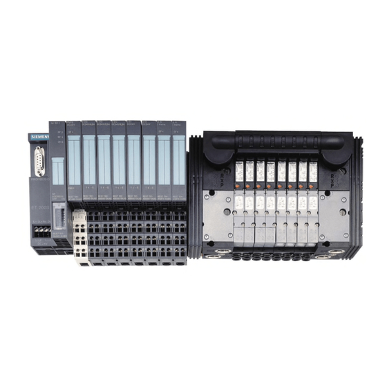
All manuals and user guides at all-guides.com AirLINE-S YSTEMBESCHREIBUNG ÜRKERT YSTEM MERKMALE DES AUFBAUS Pneumatische Einspeisung links Manometer zur Betriebsdruck- anzeige an der Station 8fach-Ventilscheibe Zwischenein- speisung 2fach-Ventilscheibe Pneumatische Ein- speisung rechts Arbeitsanschlüsse Versorgungs- und Entlüftungsanschlüsse Arbeitsanschlüsse Versorgungs- und Entlüftungsanschlüsse Typ 8644 SB 3... -
Seite 13: Aufbau Des Pneumatikblocks
All manuals and user guides at all-guides.com AirLINE-S YSTEMBESCHREIBUNG ÜRKERT YSTEM AUFBAU DES PNEUMATIKBLOCKS Der Pneumatikblock setzt sich aus folgenden Baugruppen zusammen: • Einspeisungen: Sammelanschlüsse für Versorgung, Abluft und Steuerhilfsluft • Ventilscheiben: Arbeitsanschlüsse Beispiel eines Pneumatikblocks, schematisch Elektrisch bildet das pneumatische Automatisierungssystem nach aussen eine abgeschlossene Einheit. Durch den modularen Aufbau kann die Anzahl der internen Busteilnehmer sowie Stromaufnahme des Pneumatikblocks variieren. -
Seite 14: Aufbau Der Einspeisungen
All manuals and user guides at all-guides.com AirLINE-S YSTEMBESCHREIBUNG ÜRKERT YSTEM Aufbau der Einspeisungen (10) 8 + 9 Bezeichnung Beschreibung Pneumatisches Anschlussmodul Typ MP11 (links, mitte, rechts) Elektrisches Umsetzmodul Typ ME02 (links,rechts) Schnittstelle zu elektrischem Teil des Automatisierungssystem (Feldbusknoten; elektrische Module / Klemmen) Blende Bestückungsvariante mit Manometer Rangierung... - Seite 15 All manuals and user guides at all-guides.com AirLINE-S YSTEMBESCHREIBUNG ÜRKERT YSTEM Varianten Die Einspeisungen wurden in verschiedenen Varianten konzipiert, um unterschiedlichen Anforderungen Rechnung zu tragen. So bietet das variable elektrische Anschlussmodul der Seiteneinspeisungen die Mög- lichkeit, das Pneumatiksystem mit elektrischen Systemen verschiedener Hersteller zu verwenden. Zur einfachen Inbetriebnahme und Diagnose sind Einspeisungen mit Manometer lieferbar.
-
Seite 16: Aufbau Der Ventilscheiben
All manuals and user guides at all-guides.com AirLINE-S YSTEMBESCHREIBUNG ÜRKERT YSTEM Ventilscheiben Ventilscheiben sind pneumatische Baugruppen, die mit den elektrischen Klemmen / Modulen vergleich- bar sind. Als passive Busteilnehmer integrieren (und kombinieren) sie die Funktion von digitalem Ausgang in pneumatischer Ausführung. Die Ventilscheiben werden durch Kanäle im pneumatischen Block mit Fluid versorgt. - Seite 17 All manuals and user guides at all-guides.com AirLINE-S YSTEMBESCHREIBUNG ÜRKERT YSTEM Varianten Die Varianten unterscheiden sich z. B. durch Ventiltypen 6524, 6525 Anschlussausführung D 6, M 5, M 7 Rückschlagventile ohne, R, R + S SB 8 Betriebsanleitung-Nr. 804 104...
-
Seite 18: Elektronik-Grundmodul 2Fach Typ Me02
All manuals and user guides at all-guides.com AirLINE-S YSTEMBESCHREIBUNG ÜRKERT YSTEM Elektronik-Grundmodul 2fach Typ ME02 Allgemeine Beschreibung Das Elektronik-Grundmodul integriert die elektrischen Funktionen einer Ventilscheibe. Hierzu gehört vor allem die Ansteuerung der Ventile, sowie die Kommunikation mit dem Feldbusknoten. Dezentrale Automatisierungseinheit Zentrale Gateway 1 Feldbusknoten 1... -
Seite 19: Pneumatik-Grundmodul 2Fach Typ Mp11
All manuals and user guides at all-guides.com AirLINE-S YSTEMBESCHREIBUNG ÜRKERT YSTEM Pneumatik-Grundmodul 2fach Typ MP11 Allgemeine Beschreibung Das Pneumatik-Grundmodul integriert die pneumatischen Funktionen einer Ventilscheibe. Hierzu gehört vor allem die Versorgung der Ventile mit dem zu schaltenden Fluid über ein inneres Kanal- system. -
Seite 20: Ventile
All manuals and user guides at all-guides.com AirLINE-S YSTEMBESCHREIBUNG ÜRKERT YSTEM Ventile Ventil Typ 6525 Ventil Typ 6524 5/2-Wege-Ventil 3/2-Wege-Ventil Allgemeine Beschreibung Automatisierungssysteme finden zunehmend Einsatz in allen Bereichen wo Steuerungs- und Regelungsaufgaben zu bewältigen sind. Die Ventile bilden dabei die Schnittstelle zwischen der Elektronik und Pneumatik. Die Ventile vom Typ 6524 und 6525 bestehen aus einem Vorsteuer-Wippenmagnetventil vom Typ 6104 und einem Pneumatiksitzventil. - Seite 21 All manuals and user guides at all-guides.com AirLINE-S YSTEMBESCHREIBUNG ÜRKERT YSTEM Varianten Mit dem elektrisch – pneumatischem Automatisierungssystem AirLINE Typ 8644 werden Ventile mit fol- genden Wirkungsweisen zur Verfügung gestellt: Ventile Wirkungsweise Betrieb Breite 3/2 – Wege C (NC) interne Steuerluft 10 mm 6524 3/2 –...
-
Seite 22: Technische Daten Des Pneumatikblocks
All manuals and user guides at all-guides.com AirLINE-S YSTEMBESCHREIBUNG ÜRKERT YSTEM TECHNISCHE DATEN DES PNEUMATIKBLOCKS (Unter Verwendung von Elektronikmodulen und Ventiltypen 6524/6525) Spezifische Daten Ventiltypen Typ 6524, Typ 6525 Anreihmass 11 mm Durchfluss [Q 300 l/min Druckbereich 2,5 - 7 bar Betriebsspannung 24 V/DC Nennleistung... - Seite 23 All manuals and user guides at all-guides.com AirLINE-S YSTEMBESCHREIBUNG ÜRKERT YSTEM SB 14 Betriebsanleitung-Nr. 804 104...
- Seite 24 All manuals and user guides at all-guides.com ESCHREIBUNG ESAMTSYSTEM ÜRKERT HOENIX BESCHREIBUNG GESAMTSYSTEM BÜRKERT - PHOENIX AUFBAU DES SYSTEMS ....................SP 2 FELDBUSKNOTEN PROFIBUS-DP ..................SP 3 Technische Daten des Feldbusknoten Profibus-DP ................. SP 4 Schnittstelle (Profibus) ........................SP 5 24-V-Haupteinspeisung/24-V-Segmenteinspeisung ................SP 6 24-V-Modulversorgung ........................
-
Seite 25: Beschreibung
All manuals and user guides at all-guides.com ESCHREIBUNG ESAMTSYSTEM ÜRKERT HOENIX Aufbau des Systems Konfigurationsbeispiel von Typ 8644 AirLINE in Verbindung mit Interbus-S-Anschluss in einem Schaltkasten SP 2 Betriebsanleitung-Nr. 804 104... -
Seite 26: Feldbusknoten Profibus-Dp
All manuals and user guides at all-guides.com ESCHREIBUNG ESAMTSYSTEM ÜRKERT HOENIX FELDBUSKNOTEN PROFIBUS-DP Die Busklemme koppelt eine AirLINE-Station an den Profibus an und stellt die Versorgungsspannungen für die angeschlossenen Teilnehmer bereit. Merkmale: - Profibus-Anschluss in Kupfertechnik - Datenrate: alle definierten Übertragungsraten bis 12 MBd - Möglichkeit der Einspeisung aller benötigten 24-V-Spannungen einer AirLINE-Station der Kleinsignal- ebene - Fehlerdiagnose durch LEDs an der Busklemme... - Seite 27 All manuals and user guides at all-guides.com ESCHREIBUNG ESAMTSYSTEM ÜRKERT HOENIX Technische Daten des Feldbusmoduls Profibus-DP-Busknoten Gehäusemaße (Breite x Höhe x Tiefe) 48,8 mm x 120 mm x 71,5 mm Gewicht 210 g (ohne Stecker) Zulässige Temperatur (Betrieb) 0 °C bis +55 °C Zulässige Temperatur (Lagerung/Transport) -20 °C bis +60 °C Zulässige Luftfeuchtigkeit (Betrieb)
-
Seite 28: Schnittstelle (Profibus)
All manuals and user guides at all-guides.com ESCHREIBUNG ESAMTSYSTEM ÜRKERT HOENIX Schnittstelle (Profibus) Profibus Kupferleitung (RS-485), angeschlossen über Profibus- stecker; Versorgung potentialgetrennt; Schirmung galvanisch mit der Funktionserde verbunden Empfohlene Kabellängen Siehe Systemdaten Profibus Lokalbus Anschluss Über Datenrangierung Pegel 5-V-CMOS-Signalpegel Anzahl anschließbarer AirLINE-Klemmen Begrenzung durch Software Maximal 64 Begrenzung durch Netzteil... -
Seite 29: 24-V-Haupteinspeisung/24-V-Segmenteinspeisung
All manuals and user guides at all-guides.com ESCHREIBUNG ESAMTSYSTEM ÜRKERT HOENIX 24-V-Haupteinspeisung/24-V-Segmenteinspeisung Anschlüsse siehe Tabelle TD1 Anschlusstechnik Zugfederklemmen Empfohlene Kabellängen Maximal 30 m; Kabelführung über Freiflächen ist nicht zulässig Weiterführung Über Potentialrangierung Verhalten bei Spannungseinbrüchen und Die von der Busklemme an die Potential- Unterbrechungen rangierer weitergegebenen Spannungen (Haupt- und Segmentspannung) folgen... -
Seite 30: 24-V-Modulversorgung
All manuals and user guides at all-guides.com ESCHREIBUNG ESAMTSYSTEM ÜRKERT HOENIX 24-V-Modulversorgung Logikversorgung (Potentialrangierer) Nennwert 7,5 V DC Toleranz ± 5 % Welligkeit ± 1,5 % Maximaler Ausgangsstrom 2 A DC (Derating beachten) Schutzmaßnahmen Elektronischer Kurzschluss-Schutz Analog-Versorgung (Potentialrangierer) Nennwert 24 V DC Toleranz - 15 % / + 20 % Welligkeit... -
Seite 31: Derating Der Logikversorgung Und Der Versorgung Der Analog-Klemmen
All manuals and user guides at all-guides.com ESCHREIBUNG ESAMTSYSTEM ÜRKERT HOENIX Derating der Logikversorgung und der Versorgung der Analog-Klemmen bei einer Strombelastung der Peripherie-Einspeisung an der Busklemme von max. 8 A P [%] Netzteilbelastbarkeit der Logik- und Analogversorgung in % Tu [°C] Umgebungstemperatur in °C bei einer Strombelastung der Peripherie-Einspeisung an der Busklemme... -
Seite 32: Verlustleistung
All manuals and user guides at all-guides.com ESCHREIBUNG ESAMTSYSTEM ÜRKERT HOENIX Verlustleistung Formel für die Berechnung der Verlustleistung der Elektronik Peri Σ Σ Σ Σ Σ Σ Σ Σ Σ Σ Ι Ι Ι Ι Ι Ι Ι Ι Ι Ι = 2,6 W + (1,1 ) + (0,7 Dabei sind... -
Seite 33: Schutzeinrichtungen
All manuals and user guides at all-guides.com ESCHREIBUNG ESAMTSYSTEM ÜRKERT HOENIX Beispiel: Strombelastung der Peripherie-Einspeisung: 8 A Umgebungstemperatur: 55 °C Nennbelastbarkeit der Logik- und Analogversorgung: 50 % entsprechend Grafik = 1 A, I = 0,25 A LLogik LAnalog = 1,1 W + 0,175 W PERI = 1,275 W (entspricht 50 % von 2,55 W) PERI... -
Seite 34: Anschlussmodule, Pneumatisch - Links Typ Me02
All manuals and user guides at all-guides.com ESCHREIBUNG ESAMTSYSTEM ÜRKERT HOENIX ANSCHLUSSMODULE, PNEUMATISCH - LINKS TYP ME02 Varianten Id.-Nr. Versorgungsanschluß (P) 1 Abluftanschluß (R/S) 3/5 ohne Manometer 144938 G ¼ G ¼ 150237 D 10 D 10 150236 NPT ¼ NPT ¼... -
Seite 35: Technische Daten
All manuals and user guides at all-guides.com ESCHREIBUNG ESAMTSYSTEM ÜRKERT HOENIX Technische Daten Gehäusemaße (Breite x Höhe x Tiefe) 61,9 mm x 70,4 mm x 119 mm (inkl. Rasthaken) Gewicht 220 g Zulässige Temperatur (Betrieb) 0 °C bis 55 °C Zulässige Umgebungstemperatur 0 °C bis 55 °C Zulässige Temperatur (Lagerung / Transport) -
Seite 36: Anschlussmodule, Pneumatisch - Mitte Typ Me02
All manuals and user guides at all-guides.com ESCHREIBUNG ESAMTSYSTEM ÜRKERT HOENIX ANSCHLUSSMODULE, PNEUMATISCH - MITTE TYP ME02 Varianten Id.-Nr. Versorgungsanschluß (P) 1 Abluftanschluß (R/S) 3/5 ohne Manometer 150622 G ¼ G ¼ 150623 D 10 D 10 150624 NPT ¼ NPT ¼... -
Seite 37: Technische Daten
All manuals and user guides at all-guides.com ESCHREIBUNG ESAMTSYSTEM ÜRKERT HOENIX Technische Daten Gehäusemaße (Breite x Höhe x Tiefe) 45,1 mm x 70,4 mm x 119 mm (inkl. Rasthaken) Gewicht 118 g Zulässige Temperatur (Betrieb) 0 °C bis 55 °C Zulässige Umgebungstemperatur 0 °C bis 55 °C Zulässige Temperatur (Lagerung / Transport) -
Seite 38: Anschlussmodule, Pneumatisch - Rechtstyp Me02
All manuals and user guides at all-guides.com ESCHREIBUNG ESAMTSYSTEM ÜRKERT HOENIX ANSCHLUSSMODULE, PNEUMATISCH - RECHTSTYP ME02 Varianten Id.-Nr. Versorgungsanschluß (P) 1 Abluftanschluß (R/S) 3/5 ohne Manometer 144939 G ¼ G ¼ 150239 D 10 D 10 150238 NPT ¼ NPT ¼ mit Manometer 150141 G ¼... -
Seite 39: Technische Daten
All manuals and user guides at all-guides.com ESCHREIBUNG ESAMTSYSTEM ÜRKERT HOENIX Technische Daten Gehäusemaße (Breite x Höhe x Tiefe) 47,5 mm x 70,4 mm x 119 mm Gewicht 220 g Zulässige Temperatur (Betrieb) 0 °C bis 55 °C Zulässige Umgebungstemperatur 0 °C bis 55 °C Zulässige Temperatur (Lagerung / Transport) -20 °C bis +60 °C... -
Seite 40: Installation
All manuals and user guides at all-guides.com NSTALLATION INSTALLATION INSTALLATIONSANLEITUNG ..................IN 2 Schritte zur Installation der Ventilinsel ..................... IN 2 Entfernen der Transportsicherung ..................... IN 3 Einbau des AirLINE-Systems ......................IN 4 Fluidische Installation ........................IN 5 Beschriftung der Anschlüsse ......................IN 8 Elektrische Installation ........................ -
Seite 41: Schritte Zur Installation Der Ventilinsel
All manuals and user guides at all-guides.com NSTALLATION INSTALLATIONSANLEITUNG Das AirLINE-System Typ 8644 kann mit elektrischen Automatisierungssystemen verschiedener Hersteller kombiniert werden. Beachten Sie bitte auch deren entsprechende Installationshinweise. ACHTUNG! Schalten Sie vor der Installation die Installationsumgebung spannungsfrei und si- chern Sie diese gegen Einschalten. Schritte zur Installation der Ventilinsel Entfernen der Transportsicherung (Demontage der Module von der Normschiene) Einbau (z. -
Seite 42: Entfernen Der Transportsicherung
All manuals and user guides at all-guides.com NSTALLATION Entfernen der Transportsicherung Der Pneumatikblock ist fest auf der Normschiene verschraubt. An seinen Seiten können weitere elektri- sche Module / Klemmen befestigt sein. Falls vorhanden, lösen Sie die benachbarten Mo- dule / Klemmen! Entriegeln Sie die Befestigung des Pneumatik- blocks an der Normschiene. -
Seite 43: Einbau Des Airline-Systems
All manuals and user guides at all-guides.com NSTALLATION Einbau des AirLINE-Systems (z. B. im Schaltschrank) ACHTUNG! Beachten Sie bei Arbeiten im Schaltschrank die entsprechenden Sicherheitsbe- stimmungen! Überprüfen Sie vor der Montage ob die Befestigungsschiene fest im Schaltschrank oder im System verankert ist. Beachten Sie bei der Reihenfolge des Einbaus die Vorgaben in der/den Konfigurations- datei(en). -
Seite 44: Fluidische Installation
All manuals and user guides at all-guides.com NSTALLATION Fluidische Installation Sicherheitshinweise ACHTUNG! Die pneumatischen Anschlüsse dürfen bei der Installation nicht mit Druck be- aufschlagt sein! Führen Sie die Anschlüsse möglichst großvolumig aus. Schließen Sie nicht benötigte, offene Anschlüsse mit Verschlussschrauben! Die Anschlüsse für die Vorsteuerabluft dürfen nicht verschlossen werden! Überprüfen Sie die vorschriftsmäßige Belegung der Anschlüsse 1 und 3 bzw. - Seite 45 All manuals and user guides at all-guides.com NSTALLATION Pneumatischen Anschlüsse - Ventilscheiben HINWEIS Bei 3/2 – Wege Ventilen bleiben die oberen Anschlüsse frei! 8 - fach 8fach-Ventischeibe Arbeitsanschlüsse bei 5/2-Wege-Ventilen Arbeitsanschlüsse bei 3/2-Wege-Ventilen 4 x 2 - fach 4 x 2fach-Ventilscheiben Varianten 5/2-Wege-Ventile Variante 1...
-
Seite 46: Demontage Der Steckanschlüsse
All manuals and user guides at all-guides.com NSTALLATION Hinweise zu Steckanschlüssen Für die Steckanschlüsse müssen die Schlauchleitungen folgende Anforderungen erfül- HINWEIS len: • Mindesthärte von 40 Shore D (nach DIN 53505 bzw. ISO 868); • Aussendurchmesser entsprechend DIN 73378 (max. zul. Abweichung ± 0,1 mm vom Nennmaß);... -
Seite 47: Beschriftung Der Anschlüsse
All manuals and user guides at all-guides.com NSTALLATION Beschriftung der Anschlüsse Beschriftungsfelder Beschriften Sie die Beschriftungsfelder mit den Daten der Ventilanschlüsse IN 8 Betriebsanleitung-Nr. 804 104... -
Seite 48: Elektrische Installation
All manuals and user guides at all-guides.com NSTALLATION Elektrische Installation ACHTUNG! Elektrische Leitungen dürfen nicht unter Spannung angeschlossen werden! Anschluss der elektrischen Ein- / Ausgänge (Anschlussklemmen) Öffnen Sie mit einem Schraubendreher den Steckkontakt. Führen Sie das Kabel ein. Ziehen Sie den Schraubendreher heraus. Das Kabel ist angeschlossen. - Seite 49 All manuals and user guides at all-guides.com NSTALLATION IN 10 Betriebsanleitung-Nr. 804 104...
-
Seite 50: Inbetriebnahme
All manuals and user guides at all-guides.com NBETRIEBNAHME INBETRIEBNAHME INBETRIEBNAHME DES FELDBUSKNOTEN PROFIBUS-DP ........IB 2 Der Profibus-Busknoten ........................IB 2 9poliger SUB-D-Stecker ........................IB 3 DIP-Schalter ............................IB 4 Diagnose-LEDs direkt an der Station ....................IB 5 Klemmenbelegung der Einspeiseklemme ..................IB 6 24-V-Segmenteinspeisung/24-V-Haupteinspeisung ................ -
Seite 51: Inbetriebnahme Des Feldbusknoten Profibus-Dp
All manuals and user guides at all-guides.com NBETRIEBNAHME INBETRIEBNAHME DES FELDBUSKNOTEN PROFIBUS-DP Der Profibus-Busknoten Anzeige / LEDs Profibus-Stecker Adresseinstellungen 9-poliger SUB-D Profibus-Anschluss IB 2 Betriebsanleitung-Nr. 804 104... -
Seite 52: 9Poliger Sub-D-Stecker
All manuals and user guides at all-guides.com NBETRIEBNAHME 9poliger SUB-D-Stecker 9-poliger SUB-D Profibus-Anschluss Belegung des 9-poligen SUB-D-Steckers Eingesetzt wird im PROFIBUS generell ein 9poliger Sub-D-Stecker mit Stiften. Im PROFIBUS-DP Feldbuskoppler ist immer das Gegenstück (Buchse) vorhanden. Im ersten und letzten Stecker eines Segmentes müssen jeweils ein Abschlusswiderstand von 220 Ohm und zwei Terminierungswiderstände von 390 Ohm gesetzt sein. -
Seite 53: Dip-Schalter
All manuals and user guides at all-guides.com NBETRIEBNAHME DIP-Schalter Adressierung Belegung des 10-fach-DIP-Schalters Schalter Bedeutung PROFIBUS-Adresse in binärer Darstellung ( = 0-125 in dezimaler Darstellung), Schalter 1 legt das niederwertigste Bit (2 , Schalter 7 das höherwertigste Bit (2 ) fest. Verhalten bei Datenfehler in der AirLINE-Station (Lokalbus-Fehler): ON = Datenübertragung wird nach einer Anzahl von Versuchen gestoppt. -
Seite 54: Diagnose-Leds Direkt An Der Station
All manuals and user guides at all-guides.com NBETRIEBNAHME Diagnose-LEDs direkt an der Station Anzeige / LEDs Abk. Farbe Bedeutung Erläuterung grün Hauptversorgung Versorgungsspannung im Hauptkreis für IL PB BK, Logikversorgung und Schnittstellen vorhanden. grün Segmentversorgung Versorgungsspannung im Segmentkreis vorhanden. Bus Fault Kein Datenaustausch mit dem Master Failure Select Legt die Funktion der LED FN fest:FS leuchtet:... -
Seite 55: Klemmenbelegung Der Einspeiseklemme
All manuals and user guides at all-guides.com NBETRIEBNAHME Klemmenbelegung der Einspeiseklemme Klemmen Belegung der Klemmenpunkte links rechts Farbe Abk. Bedeutung schwarz Segmentversorgung (+24V DC) Hauptklemmen-, Logik- u. Schnittstellenversorgung (+24V DC) blau Bezugspotential Funktionserde ACHTUNG! Wärmeentwicklung minimieren! Nutzen Sie zum Einspeisen der Hauptspannung und zum Einspeisen bzw. Abgreifen der Segmentspannung jeweils beide nebeneinander liegenden Kontakte. -
Seite 56: 24-V-Segmenteinspeisung/24-V-Haupteinspeisung
All manuals and user guides at all-guides.com NBETRIEBNAHME 24-V-Segmenteinspeisung/24-V-Haupteinspeisung Das Bezugspotential der Segmenteinspeisung muss dasselbe wie das der Hauptspeisung sein. Somit ist kein potentialgetrennter Aufbau der Peripherieseite möglich. Die Haupteinspeisung und die Segmenteinspeisung verfügen über Elemente zum Schutz gegen Verpolung und transiente Überspannung. ACHTUNG! Kurzschluss-Schutz gewährleisten! Die Haupteinspeisung und die Segmenteinspeisung verfügen nicht über Elemente zum... -
Seite 57: Massnahmen Vor Der Fluidischen Inbetriebnahme
All manuals and user guides at all-guides.com NBETRIEBNAHME Massnahmen vor der fluidischen Inbetriebnahme Überprüfen Sie Anschlüsse, Spannung und Betriebsdruck! Beachten Sie, dass max. Betriebsdaten (siehe Typenschild) nicht überschritten werden! Überprüfen Sie die vorschriftsmäßige Belegung der Anschlüsse 1 und 3 bzw. 5, diese dürfen auf keinen Fall vertauscht werden! Entriegeln Sie bei elektrischem Betrieb die Handbetätigung! Fluidische Inbetriebnahme... - Seite 58 All manuals and user guides at all-guides.com -DP-B ONFIGURATION DES ROFIBUS USKNOTENS KONFIGURATION DES PROFIBUS-DP- BUSKNOTENS KONFIGURATION ......................KP 2 Adressierung im Prozessabbild (1) ....................KP 3 Adressierung im Prozessabbild (2) ....................KP 3 Adressierung im Prozessabbild (3) ....................KP 4 Module aus der GSD-Datei .........................KP 5 Einstellungen in der GSD-Datei ......................
-
Seite 59: Module Aus Der Gsd-Datei
All manuals and user guides at all-guides.com -DP-B ONFIGURATION DES ROFIBUS USKNOTENS KONFIGURATION DES PROFIBUS-DP-BUSKNOTENS Module aus der GSD-Datei BESCHREIBUNG! KP 2 Betriebsanleitung-Nr. 804 104... -
Seite 60: Konfiguration Des Profibus-Dp- Busknotens
All manuals and user guides at all-guides.com -DP-B ONFIGURATION DES ROFIBUS USKNOTENS Adressierung im Prozessabbild (1) PAA Byte n IB IL 24 DO 2 1-fach Bit7 Bit6 Bit5 Bit4 Bit3 Bit2 Bit1 Bit0 IB IL 24 DO 2 1-fach Unbenutzte Bits IB IL 24 DO 2 1-fach IB IL 24 DO 2 1-fach PAA Byte n... -
Seite 61: Adressierung Im Prozessabbild (3)
All manuals and user guides at all-guides.com -DP-B ONFIGURATION DES ROFIBUS USKNOTENS Adressierung im Prozessabbild (3) IB IL 24 DO 2 4-fach IB IL 24 DO 2 4-fach PAA Byte n Bit7 Bit6 Bit5 Bit4 Bit3 Bit2 Bit1 Bit0 IB IL 24 DO 4 2-fach IB IL 24 DO 4 2-fach PAA Byte n Bit7 Bit6 Bit5 Bit4 Bit3 Bit2 Bit1... -
Seite 62: Einstellungen In Der Gsd-Datei
All manuals and user guides at all-guides.com -DP-B ONFIGURATION DES ROFIBUS USKNOTENS Einstellungen in der GSD-Datei Kennung für Module Bit7 Bit6 Bit5 Bit4 Bit3 Bit2 Bit1 Bit0 Anzahl + 1 (Byte / Worte) Eingänge Ausgänge Byte=0 Wort=1 Konsistenz Einheit=0 ges. Länge=1 Bit4 u. -
Seite 63: Einstellungen In Der Gsd-Datei (Zusammenfassen Gleicher Module)
All manuals and user guides at all-guides.com -DP-B ONFIGURATION DES ROFIBUS USKNOTENS Einstellungen in der GSD-Datei (Zusammenfassen gleicher Module) Spezielles Kennungsformat Bit7 Bit6 Bit5 Bit4 Bit3 Bit2 Bit1 Bit0 ..Anzahl User-Info = 3 Bit4 + Bit5 = 0 =1 es folgt ein Längenbyte für Eingänge =1 es folgt ein Längenbyte für Ausgänge if(A=1) Bit7 Bit6 Bit5 Bit4 Bit3 Bit2 Bit1... -
Seite 64: Auszug Aus Der Gsd-Datei
All manuals and user guides at all-guides.com -DP-B ONFIGURATION DES ROFIBUS USKNOTENS Auszug aus der GSD-Datei ;********* Digitale Ausgaenge ************************* ;********* einzelne Module, genaue Bezeichnung ******* 0x82 0x00 0xBD 0xC2 Module="IB IL 24/230 DOR 1/W" 0x82,0x00,0xBD,0xC2 Ausgänge 1 Byte Ausgänge ID-Code Längencode EndModule... - Seite 65 All manuals and user guides at all-guides.com -DP-B ONFIGURATION DES ROFIBUS USKNOTENS KP 8 Betriebsanleitung-Nr. 804 104...
-
Seite 66: Wartung Und Fehlerbehebung
All manuals and user guides at all-guides.com ARTUNG UND EHLERBEHEBUNG WARTUNG FEHLERBEHEBUNG DIAGNOSE UND FEHLERBEHEBUNG AM PROFIBUS-DP-BUSKNOTEN ....WF 2 Diagnose-LEDs direkt an der Station ....................WF 2 Ermittlung der Fehlerursache ......................WF 2 Ermittlung der Fehlerursache aus Fehlertyp und Fehlernummer ..........WF 3 Diagnose der Profibusanschaltung .................... -
Seite 67: Diagnose Und Fehlerbehebung Am Profibus-Dp-Busknoten
All manuals and user guides at all-guides.com ARTUNG UND EHLERBEHEBUNG DIAGNOSE UND FEHLERBEHEBUNG AM PROFIBUS-DP-BUSKNOTEN Diagnose-LEDs direkt an der Station Anzeige / LEDs Abk. Farbe Bedeutung Erläuterung grün Hauptversorgung Versorgungsspannung im Hauptkreis für IL PB BK, Logikversorgung und Schnittstellen vorhanden. grün Segmentversorgung Versorgungsspannung im Segmentkreis vorhanden. -
Seite 68: Ermittlung Der Fehlerursache Aus Fehlertyp Und Fehlernummer
All manuals and user guides at all-guides.com ARTUNG UND EHLERBEHEBUNG Ermittlung der Fehlerursache aus Fehlertyp und Fehlernummer Typ 1: Parameterfehler auf dem PROFIBUS-DP (SET_PRM-Telegramm) Bedeutung Ursache und Lösung keine Unterscheidung durch Fehlernummern Es ist ein Fehler während der Parametrierung des Feldbuskopplers aufgetreten. Überprüfen Sie die Parametrierung. - Seite 69 All manuals and user guides at all-guides.com ARTUNG UND EHLERBEHEBUNG Typ 2: Konfigurationsfehler auf dem Profibus (CHK_CFG-Telegramm) Nr. Bedeutung Ursachen und Lösungen Es wurden weniger AirLINE-Module Es wurden weniger AirLINE-Module konfiguriert als in der konfiguriert als physikalisch der Station vorhanden sind. Fügen Sie in der vorhanden sind.
- Seite 70 All manuals and user guides at all-guides.com ARTUNG UND EHLERBEHEBUNG Typ 3: Konfigurationsfehler in der INTERBUS- AirLINE -Station Nr. Bedeutung Ursachen und Lösungen Das AirLINE-Modul ist nicht für den Ein AirLINE-Modul ist nicht zum Betrieb an der IL PB BK Betrieb am Feldbuskoppler freigegeben.
- Seite 71 All manuals and user guides at all-guides.com ARTUNG UND EHLERBEHEBUNG Typ 4: INTERBUS-Fehler innerhalb der Station Nr. Bedeutung Ursachen und Lösungen Ein Fehler im Lokalbus- Es ist ein Fehler in der Datenübertragung zwischen den AirLINE- Signal (Data In) ist Modulen aufgetreten (Data In). Ermitteln Sie den genauen aufgetreten.
-
Seite 72: Diagnose Der Profibusanschaltung
All manuals and user guides at all-guides.com ARTUNG UND EHLERBEHEBUNG Diagnose der Profibusanschaltung Normdiagnose Gerätebezogene Diagnose Byte 01 Status 1 Byte 07 Header Byte: 0x0A Status 2 Diagnosetyp: 0x00 Byte 02 Byte 08 Status 3 Software-Version Byte 03 Byte 09 Byte 04 Master Adresse Byte 10... -
Seite 73: Fehlertyp Und Fehlernummer
All manuals and user guides at all-guides.com ARTUNG UND EHLERBEHEBUNG Fehlertyp und Fehlernummer* Fehler- Fehlernummer Bedeutung Parameterfehler auf dem PROFIBUS (SET_PRM-Telegramm) keine Unterscheidung durch Fehlernummern Konfigurationsfehler auf dem Profibus (CHK_CFG-Telegramm) Es wurden weniger AirLINE-Module konfiguriert als physikalisch vorhanden sind. Es wurden mehr AirLINE-Module konfiguriert als physikalisch vorhanden sind. Das erste Byte des speziellen Kennungsformat des AirLINE-Moduls ist fehlerhaft. -
Seite 74: Störungsbeseitigung
All manuals and user guides at all-guides.com ARTUNG UND EHLERBEHEBUNG STÖRUNGSBESEITIGUNG Störung mögliche Ursache Beseitigung Ventile schalten nicht: keine oder nicht ausreichende Betriebsspan- Überprüfen Sie den elektrischen nung; Anschluss. Stellen Sie die Betriebsspannung laut Typenschild sicher. Handbetätigung nicht in neutraler Stellung; Bringen Sie die Handbetätigung in Null- Stellung. - Seite 75 All manuals and user guides at all-guides.com ARTUNG UND EHLERBEHEBUNG WF 10 Betriebsanleitung-Nr. 804 104...
- Seite 76 SCOPE OF DELIVERY ....................GN 4 WARRANTY CONDITIONS ..................GN 4 DESCRIPTION OF BÜRKERT AirLINE-SYSTEM........BA 1 MODULAR ELECTRICAL/PNEUMATIC AUTOMATION SYSTEM TYPE 8644 AirLINE ..................BA 2 COMPOSITION OF THE PNEUMATIC BLOCK ............BA 3 Supply modules ......................BA 4 Valve units ........................ BA 7 Basic electronic module, 2-fold, type ME02 ..............
- Seite 77 All manuals and user guides at all-guides.com ONTENTS DESCRIPTION OF OVERALL SYSTEM BÜRKERT - PHOENIX .... PH 1 COMPOSITION OF THE SYSTEM ................PH 2 FIELD BUS NODE PROFIBUS DP ................PH 3 Technical data of the field bus node Profibus DP ............PH 4 Interface (Profibus) .....................
- Seite 78 All manuals and user guides at all-guides.com ONTENTS INSTALLATION ..................... IE 1 INSTRUCTIONS FOR INSTALLATION................IE 2 Steps in the installation of the valve island ..............IE 2 Removal of the transport securing device ..............IE 3 Installation of the AirLINE system.................. IE 4 Fluidic installation ......................
- Seite 79 All manuals and user guides at all-guides.com ONTENTS CONFIGURATION THE PROFIBUS-DP ............ CP 1 CONFIGURATION ......................CP 2 Addressing in the process diagram (1) ..............CP 3 Addressing in the process diagram (2) ..............CP 3 Addressing in the process diagram (3) ..............CP 4 Modules from the GSD file ..................
-
Seite 80: General Notes
All manuals and user guides at all-guides.com ENERAL OTES GENERAL NOTES SYMBOLS......................... GN 2 GENERAL SAFETY NOTES .................... GN 2 Protection from damage by electrostatic charging ................. GN 2 Safety notes for the valve ........................GN 3 SCOPE OF DELIVERY ..................... GN 4 WARRANTY CONDITIONS .................... -
Seite 81: Symbols
All manuals and user guides at all-guides.com ENERAL OTES SYMBOLS The following symbols are used in these operating instructions: marks a work step that you must carry out ATTENTION! marks notes on whose non-observance your health or the functioning of the device will be endangered NOTE marks important additional information, tips and recommendations... -
Seite 82: Safety Notes For The Valve
All manuals and user guides at all-guides.com ENERAL OTES Safety notes for the valve ATTENTION! • Keep to standard engineering rules in planning the use of and operating the device! • Take suitable precautions to prevent inadvertent operation or damage by unauthorized action! •... -
Seite 83: Scope Of Delivery
All manuals and user guides at all-guides.com ENERAL OTES SCOPE OF DELIVERY Immediately after receipt of the goods, make sure the contents are undamaged and agree with the scope of delivery stated on the packing slip. In case of irregularities, contact our customer service department at once: Bürkert Fluid Control Systems Chr.-Bürkert-Str. -
Seite 84: Description Of Bürkert Airline-System
ÜRKERT YSTEM DESCRIPTION OF BÜRKERT AirLINE-SYSTEM MODULAR ELECTRICAL/PNEUMATIC AUTOMATION SYSTEM TYPE 8644 AirLINE BA 2 COMPOSITION OF THE PNEUMATIC BLOCK ............... BA 3 Supply modules ...........................BA 4 Valve modules ............................BA 7 Basic electronic module, 2-fold, type ME02 ..................BA 9 Basic pneumatic module, 2-fold, type MP11 .................. -
Seite 85: Modular Electrical/Pneumatic Automation System Type 8644 Airline
All manuals and user guides at all-guides.com AirLINE-S ESCRIPTION OF ÜRKERT YSTEM MODULAR ELECTRICAL/PNEUMATIC AUTOMATION SYSTEM TYPE 8644 AirLINE AirLINE Type 8644 is an electrical and pneumatic automation system which has been optimized for use in control cabinets or boxes. In a through system, all electronic and pneumatic components are standardized so that if simple rules are complied with, electrical and electronic modules of differing functionality may be combined in a very simple manner. - Seite 86 All manuals and user guides at all-guides.com AirLINE-S ESCRIPTION OF ÜRKERT YSTEM CONSTRUCTIONAL FEATURES Pneumatic supply left Manometer for indication of operating pressure at the station 8-fold valve module Intermediate supply 2-fold valve module Pneumatic supply right Service ports Supply and exhaust ports Service ports Supply and exhaust...
-
Seite 87: Composition Of The Pneumatic Block
All manuals and user guides at all-guides.com AirLINE-S ESCRIPTION OF ÜRKERT YSTEM COMPOSITION OF THE PNEUMATIC BLOCK The pneumatic block is composed of the following modules: • Supply modules: collective ports for supply, exhaust and control air • Valve modules: service ports Example of a pneumatic block, schematic Supply... - Seite 88 All manuals and user guides at all-guides.com AirLINE-S ESCRIPTION OF ÜRKERT YSTEM Composition of the supply modules (10) 8 + 9 Description Description Pneumatic connector module Type MP11 (left, middle, right) Electrical converter module Type ME02 (left, right) Interface to the electrical modules of the automation system (field bus node;...
- Seite 89 All manuals and user guides at all-guides.com AirLINE-S ESCRIPTION OF ÜRKERT YSTEM Variants The supply modules have been designed in various variants to take account of differing requirements. Thus the variable electrical connector module of the end modules provides the possibility of using the pneumatic system with electrical systems of other manufacturers.
- Seite 90 All manuals and user guides at all-guides.com AirLINE-S ESCRIPTION OF ÜRKERT YSTEM Valve modules Valve modules are pneumatic components that may be compared to terminals / modules. They are passive bus participants which integrate (and combine) the function of digital output in a pneumatic version.
- Seite 91 All manuals and user guides at all-guides.com AirLINE-S ESCRIPTION OF ÜRKERT YSTEM Variants The variants differ e.g. in Valve type 6524, 6525 Connection type D 6, M 5, M 7 Check valves none, R, R + S BA 8 Operating Instructions No. 804 104...
-
Seite 92: Basic Electronic Module, 2-Fold Type Me02
All manuals and user guides at all-guides.com AirLINE-S ESCRIPTION OF ÜRKERT YSTEM Basic electronic module, 2-fold type ME02 General description The basic electronic module integrates the electrical functions of a valve module. Major functions are the actuation of the valves and communication with the field bus nodes. Decentralized automation module Central control Gateway 1... -
Seite 93: Basic Pneumatic Module, 2-Fold Type Mp11
All manuals and user guides at all-guides.com AirLINE-S ESCRIPTION OF ÜRKERT YSTEM Basic pneumatic module, 2-fold type MP11 General description The basic pneumatic module integrates the pneumatic functions of a valve module. Major functions are the supply of the valves with the fluid to be switched via an inner channel system. Several basic pneumatic modules may be connected in a row by snapping them together. -
Seite 94: Valves
All manuals and user guides at all-guides.com AirLINE-S ESCRIPTION OF ÜRKERT YSTEM Valves Valve type 6525 Valve type 6524 5/2-way valve 3/2-way valve General description Automation systems are increasingly used in all areas where control duties are to be performed. The valves form thereby the interface between electronics and pneumatics. - Seite 95 All manuals and user guides at all-guides.com AirLINE-S ESCRIPTION OF ÜRKERT YSTEM Variants With the electrical-pneumatic automation system AirLINE Type 8644 valves are provided with the following circuit functions: Valve Circuit function Width Breite Type 3/2 -way C (NC) Internal control air 10 mm 6524 3/2 -way...
-
Seite 96: Technical Data Of The Pneumatic Block
All manuals and user guides at all-guides.com AirLINE-S ESCRIPTION OF ÜRKERT YSTEM TECHNICAL DATA OF THE PNEUMATIC BLOCK (using electronic modules and valve types 6524/6525) Specific data Valve types Typ 6524, Typ 6525 Stacking width 11 mm Flow rate [Q 300 l/min Pressure range 2,5 - 7 bar... - Seite 97 All manuals and user guides at all-guides.com AirLINE-S ESCRIPTION OF ÜRKERT YSTEM BA 14 Operating Instructions No. 804 104...
-
Seite 98: Description Of Overall System Bürkert - Phoenix
All manuals and user guides at all-guides.com ESCRIPTION OF VERALL YSTEM ÜRKERT HOENIX DESCRIPTION OF OVERALL SYSTEM BÜRKERT - PHOENIX COMPOSITION OF THE SYSTEM ................... PH 2 FIELD BUS NODE PROFIBUS DP .................. PH 3 Technical data of the field bus node Profibus DP ................PH 4 Interface (Profibus) .......................... -
Seite 99: Composition Of The System
All manuals and user guides at all-guides.com ESCRIPTION OF VERALL YSTEM ÜRKERT HOENIX Composition of the system Example of a configuration of type 8644 AirLINE in combination with Interbus S connection in a control PH 2 Operating Instructions No. 804 104... -
Seite 100: Field Bus Node Profibus Dp
All manuals and user guides at all-guides.com ESCRIPTION OF VERALL YSTEM ÜRKERT HOENIX FIELD BUS NODE PROFIBUS DP The bus terminal couples an AirLINE station to the Profibus and provides the supply voltages for the connected participants. Features: - Profibus connection in copper wiring - Data rate: all defined transmission rates up to 12 MBd - Possibility of supplying all necessary 24 V voltages of an AirLINE station of the small signal level - Error diagnosis by LEDs at the bus terminal... - Seite 101 All manuals and user guides at all-guides.com ESCRIPTION OF VERALL YSTEM ÜRKERT HOENIX Technical data of the field bus Profibus DP node Housing dimensions (width x height x depth) 48,8 mm x 120 mm x 71,5 mm Weight 210 g (without plug) Permissible temperature (operation) 0 °C to +55 °C Permissible temperature (storage/transport)
-
Seite 102: Interface (Profibus)
All manuals and user guides at all-guides.com ESCRIPTION OF VERALL YSTEM ÜRKERT HOENIX Interface (Profibus) Profibus Copper conductor (RS-485), connected via Profibus connector; Power supply potential-separated; screen electrically connected to the functional earth Recommended cable lengths see Profibus system data Local bus Connection via data shunting... -
Seite 103: 24 V Main Power Supply / 24 V Segment Power Supply
All manuals and user guides at all-guides.com ESCRIPTION OF VERALL YSTEM ÜRKERT HOENIX 24 V main power supply / 24 V segment power supply Connections See Table TD1 Connection technique Tension spring terminals Recommended cable lengths max. 30 m; cable routing over free areas not permissible Forwarding Via potential shunting Behaviour on voltage drop and... -
Seite 104: 24 V Module Power Supply
All manuals and user guides at all-guides.com ESCRIPTION OF VERALL YSTEM ÜRKERT HOENIX 24 V module power supply Logic supply (potential shunter) Rated value 7,5 V DC Tolerance ± 5 % Ripple ± 1,5 % Max. output current 2 A DC (observe derating) Protective features Electronic short-circuit protection Analog supply (potential shunter) -
Seite 105: Terminals
All manuals and user guides at all-guides.com ESCRIPTION OF VERALL YSTEM ÜRKERT HOENIX Derating of the logic power supply and the power supply of the analog terminals At a current loading of the peripheral supply at the bus terminal of max. 8 A P [%] Loading capacity of the logic and analog power supplies in % Tu [°C]... -
Seite 106: Power Loss
All manuals and user guides at all-guides.com ESCRIPTION OF VERALL YSTEM ÜRKERT HOENIX POWER LOSS Formula for calculation of the power loss of the electronics Peri Σ Σ Σ Σ Σ Σ Σ Σ Σ Σ Ι Ι Ι Ι Ι Ι... -
Seite 107: Protective Features
All manuals and user guides at all-guides.com ESCRIPTION OF VERALL YSTEM ÜRKERT HOENIX Example: Current loading of periphery supply: 8A Ambient temperature: 55 °C 1. Nominal loading capacity of the logic and analog supply: 50 % (from graph) = 1 A, I = 0.25 A LLogik LAnalog... -
Seite 108: Connector Modules, Pneumatic, Left, Type Me02
All manuals and user guides at all-guides.com ESCRIPTION OF VERALL YSTEM ÜRKERT HOENIX CONNECTOR MODULES, PNEUMATIC, LEFT, TYPE ME02 Variants ID-No. Supply port (P) 1 Exhaust port (R/S) 3/5 without manometer 144938 G ¼ G ¼ 150237 D 10 D 10 150236 NPT ¼... -
Seite 109: Technical Data
All manuals and user guides at all-guides.com ESCRIPTION OF VERALL YSTEM ÜRKERT HOENIX Technical data Housing dimensions (width x height x depth) 61,9 mm x 70,4 mm x 119 mm (incl. snap-on hooks) Weight 220 g Permissible temperature (operation) 0 °C to 55 °C Permissible temperature (ambient) 0 °C to 55 °C Permissible temperature (storage/transport) -
Seite 110: Connector Modules, Pneumatic, Middle, Type Me02
All manuals and user guides at all-guides.com ESCRIPTION OF VERALL YSTEM ÜRKERT HOENIX CONNECTOR MODULES, PNEUMATIC, MIDDLE, TYPE ME02 Variants ID No. Supply port (P) 1 Exhaust port (R/S) 3/5 without manometer 150622 G ¼ G ¼ 150623 D 10 D 10 150624 NPT ¼... -
Seite 111: Technical Data
All manuals and user guides at all-guides.com ESCRIPTION OF VERALL YSTEM ÜRKERT HOENIX Technical data Housing dimensions (width x height x depth) 45,1 mm x 70,4 mm x 119 mm (incl. snap-on hooks) Weight 118 g Permissible temperature (operation) 0 °C to 55 °C Permissible temperature (ambient) 0 °C to 55 °C Permissible temperature (storage/transport) -
Seite 112: Connector Modules, Pneumatic, Right, Type Me02
All manuals and user guides at all-guides.com ESCRIPTION OF VERALL YSTEM ÜRKERT HOENIX CONNECTOR MODULES, PNEUMATIC, RIGHT, TYPE ME02 Variants ID No. Supply port (P) 1 Exhaust port (R/S) 3/5 without manometer 144939 G ¼ G ¼ 150239 D 10 D 10 150238 NPT ¼... -
Seite 113: Technical Data
All manuals and user guides at all-guides.com ESCRIPTION OF VERALL YSTEM ÜRKERT HOENIX Technical data Housing dimensions (width x height x depth) 47,5 mm x 70,4 mm x 119 mm Weight 220 g Permissible temperature (operation) 0 °C to 55 °C Permissible temperature (ambient) 0 °C to 55 °C Permissible temperature (storage/transport) - Seite 114 All manuals and user guides at all-guides.com NSTALLATION INSTALLATION INSTRUCTIONS FOR INSTALLATION ................IE 2 Steps in the installation of the valve island ..................IE 2 Removal of the transport securing device ................... IE 3 Installation of the AirLINE system ....................... IE 4 Fluidic installation ..........................
-
Seite 115: Installation
All manuals and user guides at all-guides.com NSTALLATION INSTRUCTIONS FOR INSTALLATION The AirLINE system type 8644 may be combined with the electrical automation systems of various manu- facturers. You should follow the respective installation instructions. ATTENTION! Before starting installation work, switch off the voltage in the vicinity and secure it against being switched on again. -
Seite 116: Removal Of The Transport Securing Device
All manuals and user guides at all-guides.com NSTALLATION Removal of the transport securing device The pneumatic block is securely screwed to the standard rail. Other electrical modules / terminals may be fixed on either side. If present, release the adjacent modules / termi- nals! Unlock the pneumatic block from the standard rail by turning the fixing screws anticlockwise as... -
Seite 117: Installation Of The Airline System
All manuals and user guides at all-guides.com NSTALLATION Installation of the AirLINE system (e.g. in a control cabinet) ATTENTION! During work in the control cabinet, observe the relevant safety regulations! Before mounting, check whether the mounting rail is properly anchored in the control cabinet or in the system. -
Seite 118: Fluidic Installation
All manuals and user guides at all-guides.com NSTALLATION Fluidic installation Safety notes ATTENTION! The pneumatic connections shall not be pressurized during installation! Make the connections with as large a volume as possible. Close off unused, open ports with screw caps! The ports for the pilot valve exhaust shall not be closed off! Check allocation according to instructions of ports 1 and 3 or 5: these shall under no circumstances be swapped! - Seite 119 All manuals and user guides at all-guides.com NSTALLATION Pneumatic connections - valve units NOTE With 3/2-way valves, the upper ports remain free! 8 - fach 8-fold valve unit Service ports with 5/2-way valves Service ports with 3/2-way valves 4 x 2 - fach 4 x 2-fold valve units Variants 5/2-way valves...
- Seite 120 All manuals and user guides at all-guides.com NSTALLATION Notes on plug connections For the plug connections the hoses must fulfil the following requirements: NOTE • Minimum hardness of 40 Shore D (to DIN 53505 or ISO 868); • Outside diameter to DIN 73378 (max. permissible deviation ± 0.1 mm from nominal dimension);...
- Seite 121 All manuals and user guides at all-guides.com NSTALLATION Labelling the ports Labelling area Write the valve port data on the provided Labels IE 8 Operating Instructions No. 804 104...
-
Seite 122: Electrical Installation
All manuals and user guides at all-guides.com NSTALLATION Electrical installation ATTENTION! Electrical wiring shall not be connected under voltage! Connection of the electrical inputs and outputs (terminals) Open the plug contact with a screwdriver. Insert the cable. Pull out the screwdriver. The cable is connected. Connection of the field bus node (field bus cable) As a general rule, use a 9-pole Sub-D connector. - Seite 123 All manuals and user guides at all-guides.com NSTALLATION IE 10 Operating Instructions No. 804 104...
-
Seite 124: Commissioning
All manuals and user guides at all-guides.com OMMISSIONING COMMISSIONING COMMISSIONING OF THE FIELD BUS NODE PROFIBUS DP ........CO 2 The Profibus bus node ........................CO 2 9-pole SUB-D connector ........................CO 3 DIP switches ............................CO 4 Diagnosis LEDs directly at the station ....................CO 5 Terminal configuration of the power supply terminal .............. -
Seite 125: Commissioning Of The Field Bus Node Profibus Dp
All manuals and user guides at all-guides.com OMMISSIONING COMMISSIONING OF THE FIELD BUS NODE PROFIBUS DP The Profibus bus node Display / LEDs Profibus connector Address setting 9-pole SUB-D Profibus connector CO 2 Operating Instructions No. 804 104... -
Seite 126: 9-Pole Sub-D Connector
All manuals and user guides at all-guides.com OMMISSIONING 9-pole SUB-D connector 9-pole SUB-D connector Configuration of the 9-pole SUB-D connector As a general rule, a 9-pole SUB-D connector with pins is used in the PROFIBUS. In the profibus DP field bus coupler, the matching part (socket) is always present. -
Seite 127: Dip Switches
All manuals and user guides at all-guides.com OMMISSIONING DIP switch Addressing Configuration of the 10-fold DIP switch Left Right Colour Abb- Meaning rev. black Segment supply (+24V DC) Main, bus, logic and interface supply (+24V DC) blue Reference potential Functional earth CO 4 Operating Instructions No. -
Seite 128: Diagnosis Leds Directly At The Station
All manuals and user guides at all-guides.com OMMISSIONING Diagnosis LEDs directly at the station Display / LEDs Abb- Colour Meaning Explanation rev. green Main supply Supply voltage present in main circuit for IL PB BK, logic supply and interfaces. green Segment supply Supply voltage present in segment circuit. -
Seite 129: Terminal Configuration Of The Power Supply Terminal
All manuals and user guides at all-guides.com OMMISSIONING Terminal configuration of the power supply terminal Terminals Configuration of the terminal points Left Right Colour Abb- Meaning rev. black Segment supply (+24V DC) Main, bus, logic and interface supply (+24V DC) blue Reference potential Functional earth... -
Seite 130: 24 V Segment Power Supply / 24 V Main Power Supply
All manuals and user guides at all-guides.com OMMISSIONING 24 V segment power supply / 24 V main power supply The reference potential of the segment power supply must be the same as that of the main power supply. Hence no separate potential structure is possible on the periphery side. The main power supply and the segment power supply are equipped with elements for protection against false polarity and transient overvoltage. -
Seite 131: Measures To Be Taken Before Fluidic Commissioning
All manuals and user guides at all-guides.com OMMISSIONING Measures to be taken before fluidic commissioning Check the connections, voltage and operating pressure! Make sure that the max. operating data (see rating plate) are not exceeded! Check allocation according to instructions of ports 1 and 3 or 5: these shall under no circumstances be swapped! For electrical operation, unlock the manual override! Fluidic commissioning... - Seite 132 All manuals and user guides at all-guides.com ONFIGURATION THE ROFIBUS CONFIGURING THE PROFIBUS DP CONFIGURATION ......................CP 2 Addressing in the process diagram (1) ....................CP 3 Addressing in the process diagram (2) ....................CP 3 Addressing in the process diagram (3) ....................CP 4 Modules from the GSD file ........................
-
Seite 133: Configuration The Profibus-Dp
All manuals and user guides at all-guides.com ONFIGURATION THE ROFIBUS CONFIGURATION OF THE PROFIBUS DP BUS NODE Modules from the GSD file CP 2 Operating Instructions No. 804 104... -
Seite 134: Addressing In The Process Diagram (1)
All manuals and user guides at all-guides.com ONFIGURATION THE ROFIBUS Addressing in the process diagram (1) PAA Byte n IB IL 24 DO 2 1-fold IB IL 24 DO 2 1-fach Bit7 Bit6 Bit5 Bit4 Bit3 Bit2 Bit1 Bit0 IB IL 24 DO 2 1-fach unused bits Unbenutzte Bits IB IL 24 DO 2 1-fold... -
Seite 135: Addressing In The Process Diagram (3)
All manuals and user guides at all-guides.com ONFIGURATION THE ROFIBUS Addressing in the process diagram (3) IB IL 24 DO 2 4-fach IB IL 24 DO 2 4-fold IB IL 24 DO 2 4-fach PAA Byte n Bit7 Bit6 Bit5 Bit4 Bit3 Bit2 Bit1 Bit0 IB IL 24 DO 4 2-fold IB IL 24 DO 4 2-fach... -
Seite 136: Settings In The Gsd File
All manuals and user guides at all-guides.com ONFIGURATION THE ROFIBUS Settings in the GSD file Identifier for modules bit 7 bit 6 bit 5 bit 4 bit 3 bit 2 bit 1 bit 0 Number + 1 (bytes / words) Inputs Outputs Byte=0 Word=1... -
Seite 137: Settings In The Gsd File (Bringing Together Of Identical Modules)
All manuals and user guides at all-guides.com ONFIGURATION THE ROFIBUS Settings in the GSD file (bringing together of identical modules) Special identifier format bit 7 bit 6 bit 5 bit 4 bit 3 bit 2 bit 1 bit 0 Number of user info. items = 3 Bit4 + Bit5 = 0 =1, a long byte follows for inputs =1, a long byte follows for outputs... -
Seite 138: Excerpt From The Gsd File
All manuals and user guides at all-guides.com ONFIGURATION THE ROFIBUS Excerpt from GSD file ;********* Digital outputs ************************* ;********* single modules, detailed designation******* 0x82 0x00 0xBD 0xC2 Module=“IB IL 24/230 DOR 1/W“ 0x82,0x00,0xBD,0xC2 EndModule Outputs 1 byte outputs ID code Linear code Module=“IB IL 24 DO 2-2A“... - Seite 139 All manuals and user guides at all-guides.com ONFIGURATION THE ROFIBUS CP 8 Operating Instructions No. 804 104...
-
Seite 140: Maintenance And Troubleshooting
All manuals and user guides at all-guides.com AINTENANCE AND ROUBLESHOOTING MAINTENANCE AND TROUBLESHOOTING DIAGNOSIS AND ERROR ELIMINATION AT THE PROFIBUS DP BUS NODE ..... MT 2 Diagnosis LEDs directly at the station ....................MT 2 Determining the cause of error ......................MT 2 Determining the error from error type and number ................ -
Seite 141: Diagnosis And Error Elimination At The Profibus Dp Bus Node
All manuals and user guides at all-guides.com AINTENANCE AND ROUBLESHOOTING DIAGNOSIS AND ERROR ELIMINATION AT THE PROFIBUS DP BUS NODE Diagnosis LEDs directly at the station Display/LEDs Abb- Colour Meaning Explanation rev. green Main supply Supply voltage present in main circuit for IL PB BK, logic supply and interfaces. -
Seite 142: Determining The Error From Error Type And Number
All manuals and user guides at all-guides.com AINTENANCE AND ROUBLESHOOTING Determining the error from error type and number Type 1: Parameter errors on the PROFIBUS (SET_PRM-telegram) No. Meaning Cause and remedy No distinction from error numbers An error arose during parametrization of the field bus coupler. - Seite 143 All manuals and user guides at all-guides.com AINTENANCE AND ROUBLESHOOTING Type 2: Configuration errors on the PROFIBUS (CHK_CFG-telegram) No. Meaning Cause and remedy Fewer AirLINE modules were Fewer AirLINE modules were configured than are configured than are physically present in the station. Add the modules to the present.
- Seite 144 All manuals and user guides at all-guides.com AINTENANCE AND ROUBLESHOOTING Type 3: Configuration errors in the INTERBUS Air LINE station No. Meaning Cause and remedy The AirLINE module is not released An AirLINE inline module is not released for operation at for operation at the field bus coupler.
- Seite 145 All manuals and user guides at all-guides.com AINTENANCE AND ROUBLESHOOTING Type 4: INTERBUS errors within the station No. Meaning Cause and remedy An error in the local bus An error in the data transmission between the AirLINE modules signal (Data In) has (Data In) has occurred.
-
Seite 146: Diagnosis Of The Profibus Connection
All manuals and user guides at all-guides.com AINTENANCE AND ROUBLESHOOTING Diagnosis of the Profibus connection Standard diagnosis Device-related diagnosis Byte 01 Byte 07 Status 1 Header byte: 0x0A Byte 02 Byte 08 Status 2 Diagnosis type: 0x00 Byte 03 Byte 09 Status 3 Software version Byte 04... -
Seite 147: Error Type And Number
All manuals and user guides at all-guides.com AINTENANCE AND ROUBLESHOOTING Error type and error number* Error Error number Meaning type Parameter errors on the PROFIBUS (SET_PRM-telegram) No distinction by error numbers Configuration errors on the PROFIBUS (CHK_CFG-telegram) Fewer AirLINE modules were configured than are physically present. More AirLINE modules were configured than are physically present. -
Seite 148: Service Address
All manuals and user guides at all-guides.com AINTENANCE AND ROUBLESHOOTING TROUBLESHOOTING Fault Possible cause Remedy Valves do not switch: Operating voltage not present or insufficient; Check the electrical connection. Provide operating voltage acc. to nameplate. Manual override knob not in neutral position; Turn knob to zero position. - Seite 149 All manuals and user guides at all-guides.com AINTENANCE AND ROUBLESHOOTING MT 10 Operating Instructions No. 804 104...
- Seite 150 All manuals and user guides at all-guides.com OMMAIRE Sommaire de l’instruction de service générale Type 8644 AirLINE Système d’automatisation électrique et pneumatique CONSIGNES GENERALES ............... CG 1 SYMBOLES DE PRECAUTION ................CG 2 CONSIGNES GENERALES DE SECURITE ............CG 2 Protection contre les dommages occasionnés par les charges...
- Seite 151 All manuals and user guides at all-guides.com OMMAIRE DESCRIPTION DU SYSTEME COMPLET BÜRKERT - PHOENIX ..DP 1 ARCHITECTURE DU SYSTEME ................DP 2 COUPLEUR BUS DE TERRAIN PROFIBUS-DP ............ DP 3 Caractéristiques techniques du coupleur Profibus-DP ........DP 4 Interface (Profibus) ....................
- Seite 152 All manuals and user guides at all-guides.com OMMAIRE INSTALLATION ..................... IF 1 INSTRUCTION D’INSTALLATION ................IF 2 Etapes d’installation de l’îlot de vannes ............. IF 2 Enlèvement de la sécurité de transport .............. IF 3 Intégration du système AirLINE ................IF 4 Installation fluidique ...................
- Seite 153 All manuals and user guides at all-guides.com OMMAIRE CONFIGURATION DU COUPLEUR DE BUS PROFIBUS-DP ....CC 1 CONFIGURATION ....................CC 2 Adressage en profil de processus (1) ..............CC 3 Adressage en profil de processus (2) ..............CC 3 Adressage en profil de processus (3) ..............CC 4 Modules de fichier GSD ..................
-
Seite 154: Consignes Generales
All manuals and user guides at all-guides.com ONSIGNES ENERALES CONSIGNES GENERALES SYMBOLES DE PRECAUTION ..................CG 2 CONSIGNES GENERALES DE SECURITE ..............CG 2 Protection contre les dommages occasionnés par les charges électrostatiques ......CG 2 Consignes de sécurité relatives aux vannes ..................CG 3 COUVERTURE DE LIVRAISON .................. -
Seite 155: Symboles De Precaution
All manuals and user guides at all-guides.com ONSIGNES ENERALES SYMBOLES DE PRECAUTION Vous rencontrerez les symboles de précaution suivants dans cette instruction de service: ceux-ci définissent une tâche que vous devez effectuer ATTENTION! rappelle des consignes dont la non observation est susceptible d’entraîner des dommages corporels ou de porter atteinte au fonctionnement de l’appareil CONSIGNE rappelle les informations supplémentaires importantes, les astuces et... -
Seite 156: Consignes De Sécurité Relatives Aux Vannes
All manuals and user guides at all-guides.com ONSIGNES ENERALES Consignes de sécurité relatives aux vannes ATTENTION! • Pour tout ce qui concerne l’affectation et l’exploitation de l’appareil, conformez-vous aux règles techniques de sécurité générales et en vigueur qui s’y rapportent.. •... -
Seite 157: Couverture De Livraison
All manuals and user guides at all-guides.com ONSIGNES ENERALES COUVERTURE DE LIVRAISON Dès réception de la marchandise, assurez-vous immédiatement que le contenu des colis n’a pas été endommagé en cours de transport et que le contenu de l’envoi correspond bien au bordereau d’accompagnement. -
Seite 158: Description Du Systeme
All manuals and user guides at all-guides.com AirLINE ESCRIPTION DU SYSTEME ÜRKERT DESCRIPTION DU SYSTEME BÜRKERT AirLINE SYSTEME MODULAIRE D’AUTOMATISATION ELECTRIQUE / PNEUMATIQUE ..DB 2 ARCHITECTURE DU BLOC PNEUMATIQUE..............DB 3 Architecture des alimentations ......................DB 5 Joints de vanne ..........................DB 7 Module de base électronique 2 voies Type ME02 ................ -
Seite 159: Systeme Modulaire D'automatisation Electrique/Pneumatique . Db
SYSTEME MODULAIRE D’AUTOMATISATION ELECTRIQUE / PNEUMATIQUE TYPE 8644 AirLINE Le système type 8644 AirLINE se présente comme un système d’automatisation électrique et pneumatique parfaitement optimisé pour l’intégration en armoire ou à un boîtier de commande. Tous les composants électroniques et pneumatiques sont uniformisés pour former un système de transit unique, permettant de combiner très facilement entre eux des modules pneumatiques, électriques, électroniques... - Seite 160 All manuals and user guides at all-guides.com AirLINE ESCRIPTION DU SYSTEME ÜRKERT PARTICULARITES ARCHITECTURALES Alimentation pneumatique gauche Manomètre de pression de service sur le poste Joint de vanne 8 voies Alimentation intermédiaire Joint de vanne 2 voies Alimentation pneumatique droite Raccords de service Raccords d’alimentation et de...
-
Seite 161: Architecture Du Bloc Pneumatique
All manuals and user guides at all-guides.com AirLINE ESCRIPTION DU SYSTEME ÜRKERT ARCHITECTURE DU BLOC PNEUMATIQUE Le bloc pneumatique se compose des ensembles suivants: • Alimentations: Raccords centralisés pour air d’alimentation, d’évacuation et d’asservissement de commande • Joints de vanne: raccords de service Exemple schématisé... -
Seite 162: Architecture Des Alimentations
All manuals and user guides at all-guides.com AirLINE ESCRIPTION DU SYSTEME ÜRKERT Architecture des alimentations (10) 8 + 9 N° Designation Description Module de raccordement pneumatique Modèle MP11 (gauche, central, droit) Module convertible Type ME02 (gauche, droit) électrique Interface composante électrique du système d’automatisation (Points de raccordement bus de terrain;... - Seite 163 All manuals and user guides at all-guides.com AirLINE ESCRIPTION DU SYSTEME ÜRKERT Variantes Les alimentations présentent des particularités de conception variées pour répondre à des exigences très diversifiées. Le module de raccordement électrique à extension des alimentations latérales offre la possibilité...
-
Seite 164: Vannes
All manuals and user guides at all-guides.com AirLINE ESCRIPTION DU SYSTEME ÜRKERT Îlots de vanne Les îlots de vanne sont des ensembles pneumatiques comparables aux périphériques / modules électriques. Agents passifs du bus, ils intègrent (et combinent) la fonction de sortie numérique à la fonction pneumatique. - Seite 165 All manuals and user guides at all-guides.com AirLINE ESCRIPTION DU SYSTEME ÜRKERT Variantes Les variantes se différencient entre autres par Les modèles de vanne 6524, 6525 La version des raccords D6, M 5, M 7 Les vannes anti-retour sans, R, R + S DB 8 Instructiones de service N .
-
Seite 166: Description Générale
All manuals and user guides at all-guides.com AirLINE ESCRIPTION DU SYSTEME ÜRKERT Module de base électronique 2 unités Type ME02 Description générale Le module de base électronique intègre les fonctions électriques d’un îlot de vanne. Celles-ci concernent avant tout la commande des vannes, ainsi que la communication avec les blocs de connexion au bus de terrain. - Seite 167 All manuals and user guides at all-guides.com AirLINE ESCRIPTION DU SYSTEME ÜRKERT Module de base pneumatique 2 unités Type MP11 Description générale Le module de base pneumatique intègre les fonctions pneumatiques d’un îlot de vannes. Celles-ci concernent avant tout l’alimentation des vannes en fluide de commande par un circuit de canaux inter- nes.
- Seite 168 All manuals and user guides at all-guides.com AirLINE ESCRIPTION DU SYSTEME ÜRKERT Vannes Vanne Type 6524 Vanne Type 6525 Vanne 3/2 voies Vanne 5/2 voies Description générale Les systèmes d’automatisation justifient de plus en plus leur emploi dans tous les domaines où les fonctions de commande et de régulation doivent être maîtrisées.
- Seite 169 All manuals and user guides at all-guides.com AirLINE ESCRIPTION DU SYSTEME ÜRKERT Variantes Associées au système d’automatisation électrique-pneumatique AirLINE Type 8644, les vannes peuvent assurer les fonctions suivantes: Vannes Fonction Affectation Section Type 3/2 – Voies C (NC) Air de commande interne 10 mm 6524 3/2 –...
- Seite 170 All manuals and user guides at all-guides.com AirLINE ESCRIPTION DU SYSTEME ÜRKERT Types d’effets Vanne d’orientation 3/2 voies, à commande anticipée, sortie 1 sous tension nulle et fermée Vanne d’orientation 3/2 voies, à commande anticipée, sortie 2 sous tension nulle et à pression d’ouverture Vanne d’orientation 5/2 voies, à...
-
Seite 171: Caracteristiques Techniques Du Bloc Pneumatique
All manuals and user guides at all-guides.com AirLINE ESCRIPTION DU SYSTEME ÜRKERT CARACTERISTIQUES TECHNIQUES DU BLOC PNEUMATIQUE (associé à l’utilisation de modules électroniques et des types de vannes 6524/6525) Données spécifiques Modèles de vannes type 6524, type 6525 Largeur de jonction 11 mm Débit [Q 300 l/min... -
Seite 172: Description Du Systeme Complet Bürkert - Phoenix
All manuals and user guides at all-guides.com ESCRIPTION DU SYSTEME ÜRKERT HOENIX DESCRIPTION DU SYSTEME COMPLET BÜRKERT - PHOENIX ARCHITECTURE DU SYSTEME ..................DP 2 COUPLEUR BUS DE TERRAIN PROFIBUS-DP .............. DP 3 Caractéristiques techniques du coupleur Profibus-DP ..............DP 4 Interface (Profibus) .......................... -
Seite 173: Architecture Du Systeme
All manuals and user guides at all-guides.com ESCRIPTION DU SYSTEME ÜRKERT HOENIX Architecture du système Exemple de configuration du système Type 8644 AirLINE associée à une connexion Interbus-S en boîtier de commande DP 2 Instructiones de service N . 804 104... - Seite 174 All manuals and user guides at all-guides.com ESCRIPTION DU SYSTEME ÜRKERT HOENIX BLOC DE CONNEXION PROFIBUS-DP La broche de bus couple une station AirLINE au Profibus et délivre les tensions d’alimentation au périphérique enfiché. Particularités: - Raccord Profibus de technologie cuivre - Débits de données : tous les débits de transmission définis allant jusqu’à...
- Seite 175 All manuals and user guides at all-guides.com ESCRIPTION DU SYSTEME ÜRKERT HOENIX Caractéristiques techniques du module bus de terrain pour coupleur Profibus-DP Dimensions du boîtier (Largeur x Hauteur x Profondeur) 48,8 mm x 120 mm x 71,5 mm Poids 210 g (sans la prise) Températures admissibles (Service) 0 °C à...
-
Seite 176: Interface (Profibus)
All manuals and user guides at all-guides.com ESCRIPTION DU SYSTEME ÜRKERT HOENIX Interface (Profibus) Profibus Cuivre (RS-485), raccordé par fiche Profibus; Alimentation à séparation de tension; blindage galvanique avec liaison prise de terre Longueurs de câble recommandées se référer au caractéristiques système du Profibus Lokalbus Branchement par structuration des données... - Seite 177 All manuals and user guides at all-guides.com ESCRIPTION DU SYSTEME ÜRKERT HOENIX Alimentation principale 24V / Alimentation segmentée 24V Pour les branchements, se référer au tableau TD1 Technologie de raccordement par broches à ressort d’encliquetage Longueurs de câble recommandées max.l 30 m; La conduite de câbles sur des surfaces non protégées n’est pas autorisée.
-
Seite 178: Alimentation Logique (Structuration Des Intensités)
All manuals and user guides at all-guides.com ESCRIPTION DU SYSTEME ÜRKERT HOENIX ALIMENTATION DES MODULES SOUS 24V Alimentation logique (Structuration d’intensités) Valeur de tension nominale 7,5 V DC Tolérance ± 5 % Sinusoïde ± 1,5 % Tension de sortie maximale 2 A DC (attention à... -
Seite 179: Pertes De Débit De L'alimentation Logique Et De L'alimentation Des Bornes Analogiques
All manuals and user guides at all-guides.com ESCRIPTION DU SYSTEME ÜRKERT HOENIX Perte de débit de l’alimentation logique et de l’alimentation des bornes analogiques pour une charge énergétique de l’alimentation en périphérie à la borne du bus de 8 A maximum P [%] Capacité... -
Seite 180: Puissance Dissipée
All manuals and user guides at all-guides.com ESCRIPTION DU SYSTEME ÜRKERT HOENIX Puissance dissipée Formule de calcul de la puissance dissipée par les composants électroniques Peri Σ Σ Σ Σ Σ Σ Σ Σ Σ Σ Ι Ι Ι Ι Ι Ι... -
Seite 181: Dispositifs De Protection
All manuals and user guides at all-guides.com ESCRIPTION DU SYSTEME ÜRKERT HOENIX Exemple: Intensité de charge de l’alimentation en périphérie: 8 A Température d’environnement: 55 °C Charge nominale des alimentations logique et analogique: 50 % correspondant au graphique = 1 A, I = 0,25 A LLog LAnalog... -
Seite 182: Modules De Raccordement, Pneumatique - Gauche Type Me02
All manuals and user guides at all-guides.com ESCRIPTION DU SYSTEME ÜRKERT HOENIX MODULES DE RACCORDEMENT, PNEUMATIQUE - GAUCHE TYPE ME02 Variantes Id.-N°. Raccord d’alimentation (P) 1 Raccord dépressurisation (R/S) 3/5 sans manomètre 144938 G ¼ G ¼ 150237 D 10 D 10 150236 NPT ¼... -
Seite 183: Caractéristiques Techniques
All manuals and user guides at all-guides.com ESCRIPTION DU SYSTEME ÜRKERT HOENIX Caractéristiques techniques Dimensions du boîtier (Largeur x Hauteur x Profondeur) 61,9 mm x 70,4 mm x 119 mm (comprenant ergots d’encliquetage) Poids 220 g Températures admissibles (Service) 0 °C à 55 °C Températures d’environnement admissibles 0 °C à... -
Seite 184: Modules De Raccordement, Pneumatique - Central Type Me02
All manuals and user guides at all-guides.com ESCRIPTION DU SYSTEME ÜRKERT HOENIX MODULES DE RACCORDEMENT, PNEUMATIQUE - CENTRAL TYPE ME02 Variantes Id.-N°. Raccord d’alimentation (P) 1 Raccord dépressurisation (R/S) 3/5 sans manomètre 150622 G ¼ G ¼ 150623 D 10 D 10 150624 NPT ¼... - Seite 185 All manuals and user guides at all-guides.com ESCRIPTION DU SYSTEME ÜRKERT HOENIX Caractéristiques techniques Dimensions du boîtier (Largeur x Hauteur x Profondeur) 45,1 mm x 70,4 mm x 119 mm (y compris ergots d’encliquetage) Poids 118 g Températures admissibles (Service) 0 °C à...
-
Seite 186: Modules De Raccordement, Pneumatique - Droit Type Me02
All manuals and user guides at all-guides.com ESCRIPTION DU SYSTEME ÜRKERT HOENIX MODULES DE RACCORDEMENT, PNEUMATIQUE – DROIT TYPE ME02 Variantes Id.-N°. Raccord d’alimentation (P) 1 Raccord dépressurisation (R/S) 3/5 sans manomètre 144939 G ¼ G ¼ 150239 D 10 D 10 150238 NPT ¼... -
Seite 187: Caractéristiques Techniques
All manuals and user guides at all-guides.com ESCRIPTION DU SYSTEME ÜRKERT HOENIX Caractéristiques techniques Dimensions du boîtier (Largeur x Hauteur x Profondeur) 47,5 mm x 70,4 mm x 119 mm Poids 220 g Températures admissibles (Service) 0 °C à 55 °C Températures d’environnement admissibles 0 °C à... - Seite 188 All manuals and user guides at all-guides.com NSTALLATION INSTALLATION INSTRUCTION D’INSTALLATION ..................IF 2 Etapes d’installation de l’îlot de vannes ..................... IF 2 Enlèvement de la sécurité de transport ....................IF 3 Intégration du système AirLINE ......................IF 4 Installation fluidique ..........................IF 5 Inscriptions de repérage des raccords ....................
-
Seite 189: Installation
All manuals and user guides at all-guides.com NSTALLATION INSTRUCTION D’INSTALLATION Le système AirLINE de Type 8644 peut être combiné à des systèmes d’automatisation électriques de divers fabricants. Veuillez donc vous conformer aux consignes d’installation correspondantes. ATTENTION! Avant le montage, veillez à mettre l’environnement d’installation hors tension et garantissez-le contre toute remise sous tension intempestive. -
Seite 190: Enlèvement De La Sécurité De Transport
All manuals and user guides at all-guides.com NSTALLATION Enlèvement de la sécurité de transport Le bloc pneumatique est fermement vissé sur la glissière normalisée. D’autres Modules / blocs de broches électriques peuvent être fixés sur ses faces latérales. Si cela est possible, désolidarisez également les modules / blocs de broches voisins! Déverrouillez la fixation du bloc pneumatique de la glissière normalisée. -
Seite 191: Intégration Du Système Airline
All manuals and user guides at all-guides.com NSTALLATION Intégration du système AirLINE (par ex. en armoire de commande) ATTENTION! Lors de toute intervention sur l’armoire de commande, respectez les prescripti- ons de sécurité correspondantes! Avant de procéder au montage, vérifiez si les glissières de fixation sont fortement ancrées dans l’armoire de commande ou sur l’installation. -
Seite 192: Installation Fluidique
All manuals and user guides at all-guides.com NSTALLATION Installation fluidique Consignes de sécurité ATTENTION! Les raccords pneumatiques ne doivent pas être soumis à pressurisation au cours de leur installation! Ouvrez les alimentations en grand. Les raccords libres non utilisés doivent être obturés au moyen de capuchons filetés ! Les raccords destinés à... - Seite 193 All manuals and user guides at all-guides.com NSTALLATION Raccords pneumatiques - Îlot de vannes CONSIGNE Les raccords supérieurs des vannes directionnelles 3/2 voies doivent rester libres! 8 - fach 8 - blocs Raccords de service pour vannes directionnelles 5/2 voies Raccords de service pour vannes directionnelles 3/2 voies...
- Seite 194 All manuals and user guides at all-guides.com NSTALLATION Consignes relatives aux buses de raccordement CONSIGNE Pour s’adapter parfaitement aux buses de raccordement, les conduites flexibles doivent présenter les exigences suivantes: • Indice de dureté minimum de 40 Shore D (selon norme DIN 53505 ou ISO 868); •...
-
Seite 195: Inscriptions De Repérage Des Raccords
All manuals and user guides at all-guides.com NSTALLATION Inscriptions de repérage des raccords Les champs d’inscription Inscrivez les données des raccords de van- ne sur les champs d’inscription prévus IF 8 Instructiones de service N . 804 104... -
Seite 196: Installation Électrique
All manuals and user guides at all-guides.com NSTALLATION Installation électrique ATTENTION! Les circuits électriques ne doivent pas être sous tension! Branchement des entrées / sorties électriques (Bornes de raccordement) Ouvrez le contacteur à pression à l’aide d’un tour- nevis. Engagez le câble dans l’ouverture de la borne. Retirez le tournevis. - Seite 197 All manuals and user guides at all-guides.com NSTALLATION IF 10 Instructiones de service N . 804 104...
-
Seite 198: Mise En Service
All manuals and user guides at all-guides.com ISE EN ERVICE MISE EN SERVICE MISE EN SERVICE DU COUPLEUR DE CONNEXION PROFIBUS-DP ......MS 2 Bloc de connexion Profibus ....................... MS 2 Fiche SUB-D à 9 pôles ........................MS 3 Bloc micro-contacteurs ........................MS 4 Témoins LED de diagnostic placés directement sur la station ............ - Seite 199 All manuals and user guides at all-guides.com ISE EN ERVICE MISE EN SERVICE DU COUPLEUR DE CONNEXION BUS DE TERRAIN PROFIBUS-DP Le coupleur de connexion Profibus Affichage / LEDs Broche Profibus Réglages d’adresse Fiche SUB-D 9 pôles Branchement MS 2 Instructiones de service N .
-
Seite 200: Fiche Sub-D À 9 Pôles
All manuals and user guides at all-guides.com ISE EN ERVICE Fiche SUB-D 9 pôles Fiche SUB-D 9 pôles Branchement Profibus Agencement de la fiche SUB-D à 9 pôles En règle générale, une fiche Sub-D 9 pôles à broches est intégrée au PROFIBUS. Le coupleur bus de terrain PROFIBUS-DP est toujours accompagné... - Seite 201 All manuals and user guides at all-guides.com ISE EN ERVICE Micro-contacteurs Adressage Agencement du bloc à 10 micro-contacteurs Contac- Affectation des contacteurs teurs Adresse PROFIBUS en représentation binaire ( = 0-125 en représentation décimale), le contacteur 1 définit l’octet ayant la valeur la plus faible (2 ) le contacteur 7 celui ayant la valeur la plus importante (2 Comportement en cas d’erreur de donnée de la station AirLINE (bus local en défaut) :...
-
Seite 202: Témoins Led De Diagnostic Placés Directement Sur La Station
All manuals and user guides at all-guides.com ISE EN ERVICE Témoins LED de diagnostic placés directement sur la station Affichage / LEDs Couleur Désignation Signification vert Alimentation principale Tension d’alimentation circuit principal IL PB BK, alimentations logique et d’interface disponibles. vert Alimentation segmentée Tension d’alimentation disponible pour circuit segmenté. - Seite 203 All manuals and user guides at all-guides.com ISE EN ERVICE Disposition des broches du bornier d’alimentation Klemmen Broches Disposition des points de brochage Gauche Droit Couleur Signification noir Alimentation segmentée (+24V DC) rouge Brochage principal et du bus, alimentation numérique et d’interface (+24V DC) bleu Intensité...
-
Seite 204: Alimentation Segmentée En 24V / Alimentation Principale En 24V
All manuals and user guides at all-guides.com ISE EN ERVICE Alimentation segmentée en 24V / Alimentation principale en 24V Les intensités de référence de l’alimentation segmentée et de l’alimentation principale doivent être identiques, ce qui empêche une structuration d’intensité séparée de la boucle périphérique. L’alimentation principale et l’alimentation segmentée bénéficient d’éléments de protection contre toute polarisation et surtension intempestive. - Seite 205 All manuals and user guides at all-guides.com ISE EN ERVICE Mesures préliminaires à la mise en service fluidique Vérifiez les raccords, la tension, et la pression de service! Veillez à ce que les caractéristiques de service maximales (voir panneau des types) ne soient pas dépassées! Vérifiez que le schéma des branchements 1 et 3 ou 5 est bien conforme aux prescriptions, ceux-ci ne doivent en aucun cas être intervertis!
- Seite 206 All manuals and user guides at all-guides.com ONFIGURATION DU OUPLEUR DE ROFIBUS CONFIGURATION DU COUPLEUR DE BUS PROFIBUS-DP CONFIGURATION ......................CC 2 Adressage en profil de processus (1) ....................CC 3 Adressage en profil de processus (2) ....................CC 3 Adressage en profil de processus (3) ....................
-
Seite 207: Configuration Du Coupleur De Bus Profibus-Dp
All manuals and user guides at all-guides.com ONFIGURATION DU OUPLEUR DE ROFIBUS CONFIGURATION DU COUPLEUR DE BUS PROFIBUS-DP Modules de fichier GSD CC 2 Instructiones de service N . 804 084... - Seite 208 All manuals and user guides at all-guides.com ONFIGURATION DU OUPLEUR DE ROFIBUS Adressage profil de processus (1) PAA Byte n IB IL 24 DO 2 1-domaine IB IL 24 DO 2 1-fach PAA Octet n Bit7 Bit6 Bit5 Bit4 Bit3 Bit2 Bit1 Bit0 IB IL 24 DO 2 1-fach...
- Seite 209 All manuals and user guides at all-guides.com ONFIGURATION DU OUPLEUR DE ROFIBUS Adressage profil de processus (3) IB IL 24 DO 2 4-fach IB IL 24 DO 2 4-domaine IB IL 24 DO 2 4-fach PAA Octet n PAA Byte n Bit7 Bit6 Bit5 Bit4 Bit3 Bit2 Bit1 Bit0 IB IL 24 DO 4 2-domaine...
-
Seite 210: Paramétrages Du Fichier Gsd
All manuals and user guides at all-guides.com ONFIGURATION DU OUPLEUR DE ROFIBUS Paramétrages du fichier GSD Identification modules bit 7 bit 6 bit 5 bit 4 bit 3 bit 2 bit 1 bit 0 Nombre + 1 (Octet / Mots) Entrées Sorties Octet=0 Mot=1... - Seite 211 All manuals and user guides at all-guides.com ONFIGURATION DU OUPLEUR DE ROFIBUS Paramétrages du fichier GSD (centralisation de modules identiques) Format d’identification spécifique bit 7 bit 6 bit 5 bit 4 bit 3 bit 2 bit 1 bit 0 Nombre User-Info = 3 Bit4 + Bit5 = 0 =1 suit un octet de longueur pour les entrées =1 suit un octet de longueur pour les sorties...
-
Seite 212: Extrait Du Fichier Gsd
All manuals and user guides at all-guides.com ONFIGURATION DU OUPLEUR DE ROFIBUS Extrait de fichier GSD ;********* Sorties numériques * ************************ ;********* Modules individuels, ******* 0x82 0x00 0xBD 0xC2 Modules=»IB IL 24/230 DOR 1/W» 0x82,0x00,0xBD,0xC2 Modules terminaux Sorties 1 Octet sorties Code ID Code Modules=»IB IL 24 DO 2-2A»... - Seite 213 All manuals and user guides at all-guides.com ONFIGURATION DU OUPLEUR DE ROFIBUS CC 8 Instructiones de service N . 804 084...
- Seite 214 All manuals and user guides at all-guides.com AINTENANCE MAINTENANCE ET LEVEE DES ERREURS DIAGNOSTIC ET LEVEE DES ERREURS AU NIVEAU DU COUPLEUR DE BUS PROFIBUS-DP ......................... ML 2 Témoins - LED de diagnostic placés directement sur la station ............. ML 2 Détermination de la cause d’erreur ....................
-
Seite 215: Diagnostic Et Levee Des Erreurs Au Niveau Du Coupleur De Bus Profibus-Dp
All manuals and user guides at all-guides.com AINTENANCE DIAGNOSTIC ET LEVEE DES ERREURS AU NIVEAU DU COUPLEUR DE BUS PROFIBUS-DP Témoins LED de diagnostic placés directement sur la station Affichage / LEDs Couleur Signification Explications vert Alimentation principale Tension d’alimentation circuit principal IL PB BK, alimentations logique et d’interface disponibles. - Seite 216 All manuals and user guides at all-guides.com AINTENANCE Determination de la cause de l'erreur en fonction de son type et de son numero Type 1: Erreur de paramétrage du PROFIBUS-DP (Télégramme SET_PRM) Signification Cause et solution aucune différenciation par les numéros d’erreur Il s’agit d’une erreur apparue au cours du paramétrage du coupleur de bus de terrain.
- Seite 217 All manuals and user guides at all-guides.com AINTENANCE Type 2 : Erreur de configuration du Profibus (Télégramme CHK_CFG) N° Signification Causes et solutions Le nombre de modules AirLINE Le nombre de modules AirLINE configurés est inférieur à configurés est inférieur à celui des celui des modules disponibles de la station.
- Seite 218 All manuals and user guides at all-guides.com AINTENANCE Type 3 : Erreur de configuration INTERBUS- Station AirLINE Signification Causes et solutions Le module AirLINE n’est pas autorisé Un module AirLINE n’est pas autorisé à fonctionner avec à fonctionner avec le coupleur de bus l’IL PB BK.
- Seite 219 All manuals and user guides at all-guides.com AINTENANCE Type 4 : Erreur INTERBUS interne à la station Signification Causes et solutions Apparition d’une erreur au Une erreur de transmission de données est survenue entre les signal d’entrée bus local modules AirLINE (Data In). Déterminez la position exacte de (Data In).
- Seite 220 All manuals and user guides at all-guides.com AINTENANCE Diagnostic de branchement Profibus Diagnostic normalisé Diagnostic lié aux appareils Octet 01 Octet 07 Statut 1 Octet d’en-tête : 0x0A Octet 02 Octet 08 Statut 2 Type de diagnostic : 0x00 Octet 03 Octet 09 Statut 3 Version logicielle...
-
Seite 221: Type Et Numéro D'erreur
All manuals and user guides at all-guides.com AINTENANCE Type et numéro d’erreur* Type Numéro Signification d’erreur d’erreur Erreurs de paramétrage du PROFIBUS (Télégramme SET_PRM) aucune différenciation des numéros d’erreur Erreurs de configuration sur Profibus (Télégramme CHK_CFG) Le nombre des modules AirLINE configurés est inférieur à celui des modules physiques disponibles Le nombre des modules AirLINE configurés est supérieur à... -
Seite 222: Elimination Des Anomalies
All manuals and user guides at all-guides.com AINTENANCE ELIMINATION DES ANOMALIES Anomalies Causes possibles Elimination Les vannes ne sont Tension de service nulle ou insuffisante; Vérifiez le branchement électrique. pas activées: Assurez la tension de service au vu du panneau de type. La commande manuelle n'est pas en Amenez la commande manuelle en position neutre. - Seite 223 All manuals and user guides at all-guides.com AINTENANCE ML 10 Instructiones de service N . 804 084...
- Seite 224 All manuals and user guides at all-guides.com Berlin: Tel. (0 30) 67 97 17-0 Dresden: Tel. (03 59 52) 36 30-0 Steuer- und Regeltechnik Frankfurt: Tel. (0 61 03) 94 14-0 Christian-Bürkert-Str. 13-17 Hannover: Tel. (05 11) 902 76-0 74653 Ingelfingen Dortmund: Tel.