Herunterladen Inhalt Inhalt Diese Seite drucken
Vorschau ausblenden Andere Handbücher für PP 45 RHK:
Inhaltsverzeichnis

Werbung

Verfügbare Sprachen

Verfügbare Sprachen

Montageanleitung Rohbau
Installation instructions
Notice de montage Gros œuvre
www.maico-ventilatoren.com
PushPull-Lüftungssysteme
PushPull ventilation systems
Installations de ventilation PushPull
PP 45 RHK
PP 45 RHL
PP 45 AK
PP 45 AE
PP 45 AW
PP 45 AS
PP 45 AKR
PP 45 AKB
PP 45 LE
PP 45 LEV
PP 45 LEW90
PPB 30 AK
PPB 30 AE
PPB 30 AW
PPB 30 AS

Werbung

Inhaltsverzeichnis
loading

Inhaltszusammenfassung für Maico PP 45 RHK

  • Seite 1 Montageanleitung Rohbau Installation instructions Notice de montage Gros œuvre PP 45 RHK PP 45 RHL PP 45 AK PP 45 AE PP 45 AW PP 45 AS PP 45 AKR PP 45 AKB PP 45 LE PP 45 LEV PP 45 LEW90...
  • Seite 2: Inhaltsverzeichnis

    Inhaltsverzeichnis Weitere Vorgehensweise bei der End- Inhaltsverzeichnis montage..........Steuerungskonzept PP 45....9.1 Montagehinweise Unterputzdose ..17 Steuerungskonzept PPB 30 ....9.2 Nach Innenputz- und Malerarbeiten Vorwort ..........10 Einbaumaße ........... 18 Sicherheit ..........10.1 PP 45 AK......... 18 Lieferumfang ......... 10.2 PP 45 AKR / PP 45 AKB ....
  • Seite 3: Steuerungskonzept Pp 45

    Steuerungskonzept PP 45 Steuerungskonzept PP 45...
  • Seite 4: Steuerungskonzept Ppb 30

    Steuerungskonzept PPB 30 Steuerungskonzept PPB 30...
  • Seite 5: Vorwort

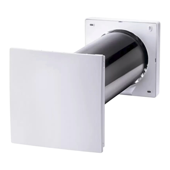
    Inbetriebnahme PPB 30 AE / PPB 30 AS → Montageanleitung und den vielfältigen Außenabdeckung. Einstellmöglichkeiten • Rohbauhülse kurz PP 45 RHK (0059.0081) des Lüftungssystems • Rohbauhülse lang PP 45 RHL (0059.0082) • Für Inbetriebnahme- • Wandhülse, Putzschutzdeckel und Keile →...
  • Seite 6: Bestimmungsgemäße Verwendung

    4 Bestimmungsgemäße Verwendung Für PPB 30-Geräte ist eine Außenabdeckung 4 Bestimmungsgemäße Verwen- PPB 30 AK/AE/AW/AS vorgeschrieben. Diese dung Außenabdeckungen führen das Kondensat über die Seitengitter ab. PP 45-/PPB 30-Geräte mit Wärmerückgewinnung PP 45-/PPB 30-Geräte sind ausschließlich für dienen zur Entlüftung/Belüftung von Wohnungen, den häuslichen Gebrauch und ähnliche Zwecke Büros oder vergleichbaren Räumen.
  • Seite 7: Technische Daten

    PPB 30 K-Gerät mit balanciertem Betrieb für die Dauerlüftung im Bad Außendurchmesser DN 160 Raumluftsteuerung RLS 45 K Wandhülse PP 45 RHK: 500 mm Zuluft- und Abluft mit Richtungswechsel max. Länge PP 45 RHL: 800 mm Außenluft- und Fortluft mit Richtungswech- Wandstärke min.
  • Seite 8: Montagevorbereitungen

    7 Montagevorbereitungen • Geeignetes Befestigungsmaterial für die Monta- Lüftungsgeräte Max. 6 PP 45-Geräte ge der Wandhülse und Außenabdeckung ist (3 x 2 Gerätepaare) je PP 45 O / PP 45 K bauseitig bereitzustellen. Leistungsteil. • Kernlochdurchmesser DN 162. Zur Sicherstel- Ab Sternpunkt 25 m Ka- lung der Kondensatabführung über die Au- Leistungsteil PP 45 LT belanschlusslänge zum...
  • Seite 9: Montage

    8.1.1 Montage der Wandhülse PP 45 RC: NYM 3 x 1,5mm² PP 45 RHK / PP 45 RHL für PP 45-Geräte PPB 30 O / PPB 30 K: Steuerleitungen: Typ J- Y (ST) Y 2 x 2 x 0,8 mm. Max. 25 m ab Stern- punkt, bis Sternpunkt max.
  • Seite 10: Positionierung Der

    8 Montage PP 45 RHK / PP 45 RHL für PPB 30-Geräte Vorgeschriebener Wandstärke W Wandhülsen-Über- stand für PP 45 RHK / PP 45 RHL PP 45 AK W + 10...15 mm PP 45 AE PP 45 AW PP 45 AS PP 45 AKR W + 0...4 mm...
  • Seite 11: Außenabdeckung

    8 Montage 5. Wandhülse in das Kernloch einsetzen, so 8.2.1 Montage Außenabdeckungen dass diese an der Außenwand übersteht. PP 45 AKR / PP 45 AKB Wandhülsen-Überstand zur Außenwand be- 1. Nach Beendigung der Außenputzarbeiten den achten! Putzschutzdeckel entfernen. Überstand Wand- 6. Wandhülse mit mitgelieferten Putzschutzde- hülse 0 bis max.
  • Seite 12: Montage Außenabde- Ckungen Pp 45 Ak / Pp

    8 Montage 7. Frontabdeckung zur Außenwand hin dauer- elastisch und witterungsbeständig abdichten. Für PP 45 AKB silikonfreies Dichtmaterial ver- wenden. PP 45 AKB kann mit einer beliebigen Fassadenfarbe überstrichen werden. 8.2.2 Montage Außenabdeckungen PP 45 AK / PP 45 AE / PP 45 AW / PP 45 AS (nach Fertigputz der Außenwand) Bohrabstände Außenabdeckung PP 45 AE / PP 45 AW / PP 45 AS (Edelstahl/weiß/schwarz)
  • Seite 13: Montage Außenabdeckungen Ppb 30 Ak

    8 Montage 6. Frontabdeckung zur Außenwand hin dauer- elastisch und witterungsbeständig abdichten (Pfeile S2). Geeignetes Dichtungsmaterial ist bauseitig bereitzustellen. 8.2.3 Montage Außenabdeckungen PPB 30 AK und PPB 30 AE / PPB 30 AW / PPB 30 AS (nach Fertigputz der Außenwand) Position der Außenabdeckung und Wandhül- se →...
  • Seite 14: Frontabdeckung

    8 Montage 1. Frontabdeckung von unten auf das Gehäuse 8.3 Frontabdeckung setzen – die beiden Schlitze der Frontabde- ckung müssen in die Gehäusenasen einrasten 8.3.1 PPB 30 AK (siehe Kreisausschnitte). ACHTUNG: Fehlluft, falls die Dämmmatte der Frontabdeckung nicht dicht anliegt. Dämm- 2.
  • Seite 15: Montagevorbereitungen

    8 Montage 8.6.1 Montagevorbereitungen 1. Montageposition bestimmen. Auf eine ebene Wandfläche achten. Abmessungen beachten. Um das Laibungs-Außengitter eine 7 mm um- laufende Putzkante berücksichtigen. Das Laibungselement sollte nicht in Kombi- nation mit einer Fassadenwärmedämmung mit einer Dicke von 100 mm verbaut werden. WARNUNG Verletzungsgefahr, falls sich Laibungselement oder Wandhülse löst.
  • Seite 16: Laibungselement Und Laibungs-Außengitter Montieren

    8 Montage 8.6.4 Laibungselement und Laibungs-Außen- gitter montieren 1. Außenwandseitig Gummidichtung-Wandhülse auf die überstehende Wandhülse schieben. 2. Laibungselement bis zum Anschlag auf die Wandhülse/Gummidichtung schieben. Der Lai- bungskanal muss plan auf der Wand auflie- gen. Wandhülse kürzen, falls der Laibungska- nal von der Wand absteht.
  • Seite 17: Laibungs-Außengitter

    9 Weitere Vorgehensweise bei der Endmontage 5. Laibungselement an der Wand fixieren (z. B. 9 Weitere Vorgehensweise bei der mit Montagekleber). Alternativ das Laibungs- Endmontage element mit geeigneten Schrauben an die Wand schrauben oder an 2 bis 3 Positionen 9.1 Montagehinweise Unterputzdose mit einem Lochband umwickeln und mit der Wand verschrauben.
  • Seite 18: Einbaumaße

    10 Einbaumaße 10.4 PP 45 LE 10 Einbaumaße (nicht mit PPB 30 kombinierbar) 10.1 PP 45 AK 10.2 PP 45 AKR / PP 45 AKB Länge ab Mitte Kernbohrung max. Länge ab Mitte Kernbohrung min. 10.5 PP 45 LEW90 10.3 PP 45 AE / PP 45 AW / PP 45 AS 10.6 PP 45 LEV (nicht mit PPB 30 kombinierbar)
  • Seite 19: Ppb 30 O / Ppb 30 K

    11 Umweltgerechte Entsorgung 10.7 PPB 30 O / PPB 30 K 10.8 PPB 30 O / PPB 30 K + PP 45 VS 10.9 Abmessungen weiterer Kompo- 11 Umweltgerechte Entsorgung nenten Altgeräte und Elektronikkomponenten dür- fen nur durch elektrotechnisch unterwiesene Komponente Abmessungen Fachkräfte demontiert werden.
  • Seite 20: Impressum

    Füllmaterialien, Kunststoffe) über entspre- chende Recyclingsysteme oder Wertstoffhöfe. 3. Beachten Sie die jeweils landesspezifischen und örtlichen Vorschriften. Impressum © Maico Elektroapparate-Fabrik GmbH. Deut- sche Original-Betriebsanleitung. Druckfehler, Irr- tümer und technische Änderungen vorbehalten. Die in diesem Dokument erwähnten Marken, Handelsmarken und geschützte Warenzeichen beziehen sich auf deren Eigentümer oder deren...
  • Seite 21 Table of contents 9.1 Installation information for flush- Table of contents mounted box ........PP 45 control concept ......9.2 After internal plastering and painting PPB 30 control concept ......10 Installation dimensions ......36 Preface ............ 10.1 PP 45 AK .......... 36 Safety ............
  • Seite 22: Pp 45 Control Concept

    PP 45 control concept PP 45 control concept...
  • Seite 23: Ppb 30 Control Concept

    PPB 30 control concept PPB 30 control concept...
  • Seite 24: Preface

    PPB 30 in- • Shell sleeve, short PP 45 RHK (0059.0081) stallation instructions • Shell sleeve, long PP 45 RHL (0059.0082) for final assembly kit • Wall sleeve, plaster protective cover and •...
  • Seite 25: Application Examples

    5 Application examples PP 45 are ventilation units, which are generally only suited to use in supply air rooms. To achieve efficient ventilation of these units, we would re- commend operating the PP 45 in pairs, with al- ternating ventilation and air extraction. We recom- mend multiple ventilation units per room for larger residential units.
  • Seite 26: Technical Data

    DN 160 the same time, with balanced operation. A PPB 30 K fan ventilates the room with air which has Wall sleeve PP 45 RHK: 500 mm been pre-warmed in the heat exchanger. The max. length PP 45 RHL: 800 mm other PPB 30 K fan transfers the thermal energy Wall thickness min.
  • Seite 27: Number Of Ventilation Units

    7 Preparation for installation 6.3 Number of ventilation units 7 Preparation for installation Installation information Combinations Quantity • PP 45 units are only suited for supply air rooms. Ventilation units • PPB 30 units are the ideal choice for exhaust Ventilation units Max.
  • Seite 28: Installation

    • Observe electrical supply line to suit unit vari- ant: PP 45 RHK / PP 45 RHL for PP 45 units PP 45 O / PP 45 K: Control cable type J-Y (ST) Y 2 x 2 x 0.8 mm. Max. 25 m from star point, up to star point max.
  • Seite 29: Positioning Of Wall Sleeve

    8 Installation 8.1.3 Installation of wall sleeve B PPB 30 cable feedthrough NOTICE: Unit damage and damage to brick- M Wall sleeve centre work caused by condensate in the event of in- 8.1.2 Positioning of wall sleeve correct installation where condensate runs to- wards the interior wall if the core hole is drilled at too slight an incline.
  • Seite 30: External Cover

    8 Installation 10.If walls have a wooden construction, addition- 2. Apply mounting adhesive provided by cus- ally seal the interfaces to this construction. tomer in dots or lines to the underside of the Stick sealing strips to the wall sleeve in these condensate drain (arrow) and attach it to the areas.
  • Seite 31: Installation Of External

    8 Installation 3. Align housing horizontally and centred with wall sleeve, mark 4 fixing holes, position dow- els and screw down housing to exterior wall with 4 screws. Suitable mounting material is to be provided by the customer. Drilling distances for external cover PP 45 AK (plastic) Housing Sealing strip (silicone)
  • Seite 32: Ppb 30 Ae / Ppb

    8 Installation Sealing strip Housing Silicon ring 4. On the side of the housing facing the wall, at- tach a silicon ring [S] around the entire hole to seal it off from the wall. 1. Remove plaster protective cover, place drilling template over the wall sleeve, align it and Housing mark the fixing holes.
  • Seite 33: Ppb 30 Ae / Ppb 30 Aw / Ppb 30 As

    8 Installation 1. Place the front cover onto the housing from 8.6 Soffit elements PP 45 LE, above and swing it downwards. PP 45 LEV and PP 45 LEW90 2. The front cover must audibly engage in the Soffit elements not suitable for PPB 30 two locking levers at the bottom.
  • Seite 34: Preparation For Installa

    8 Installation Installation position of window soffit: The con- 2. The wall sleeve must protrude 20 to 25 mm densate drip edge must protrude 20 to 25 mm beyond the exterior wall so that the soffit ele- beyond the external plastering, once this plaster- ment can be attached.
  • Seite 35: Install Soffit Element And Soffit External Grille

    8 Installation For extensions PP 45 LEV or 90° angle ele- ments PP 45 LEW90: Apply mounting adhesive all around slot on face end. Glue the soffit ele- ment with the extension or angle. Be sure to seal around the couplings, e.g. with adhesive tape. Saw off extension to desired installation dimen- sion.
  • Seite 36: Next Steps For Final Mounting

    9 Next steps for final mounting 9. Only mount soffit external grille once the plas- 10 Installation dimensions tering is complete. 10.1 PP 45 AK Formation of surface rust: External factors (e.g., air containing sulphur dioxide or salt, dust containing iron etc.) may cause surface rust to form on stainless steel.
  • Seite 37: Pp 45 Le

    10 Installation dimensions 10.4 PP 45 LE 10.6 PP 45 LEV (cannot be combined with PPB 30) (cannot be combined with PPB 30) Length from centre of core hole max. Length from centre of core hole min. 10.5 PP 45 LEW90...
  • Seite 38: Ppb 30 O / Ppb 30 K

    11 Environmentally responsible disposal 10.7 PPB 30 O / PPB 30 K 10.8 PPB 30 O / PPB 30 K + PP 45 VS 10.9 Dimensions of further compon- 11 Environmentally responsible ents disposal Old devices and electronic components may Components Dimensions only be dismantled by specialists with elec-...
  • Seite 39: Acknowledgements

    3. Observe the respective country-specific and local regulations. Acknowledgements © Maico Elektroapparate-Fabrik GmbH. Trans- lation of the original operating instructions. Mis- prints, errors and technical changes are reserved. The brands, brand names and protected trade marks that are referred to in this document refer to their owners or their products.
  • Seite 40 Sommaire 8.6.3 Préparation de l'élément Sommaire d'embrasure ....Concept de commande PP 45 ..... 41 8.6.4 Monter l'élément d'em- brasure et la grille exté- Concept de commande PPB 30 ... 42 rieure d'embrasure..Avant-propos ........43 Suite de la marche à suivre lors du Sécurité..........
  • Seite 41: Concept De Commande Pp 45

    Concept de commande PP 45 Concept de commande PP 45...
  • Seite 42: Concept De Commande Ppb 30

    Concept de commande PPB 30 Concept de commande PPB 30...
  • Seite 43: Avant-Propos

    1 Avant-propos • Remettez les notices au propriétaire / à l'exploi- 1 Avant-propos tant pour conservation. La présente notice contient des informations im- 3 Volume de fourniture portantes pour la préparation du montage et pour le montage des composants de l'appareil Volume de fourniture en fonction de la confi- en phase de gros œuvre.
  • Seite 44: Utilisation Conforme

    4 Utilisation conforme Pour les appareils PP 45, une protection externe 4 Utilisation conforme PP 45 AK/AE/AW/AS (voir accessoires) avec lar- Les appareils PP 45 / PPB 30 à récupération de mier pour condensat intégré est obligatoire. Une chaleur servent à évacuer / insuffler l'air des ap- combinaison avec l'élément d'embrasure partements, bureaux ou espaces similaires.
  • Seite 45: Installation Of External Covers Pp 45 Ak / Pp

    Diamètre extérieur DN 160 Air extérieur et air rejeté avec changement de direction Gaine murale PP 45 RHK: 500 mm longueur max. PP 45 RHL: 800 mm Solution de ventilation dans un appartement 3 Épaisseur du mur 265 mm pièces avec appareils de ventilation PPB 30 K min.
  • Seite 46: Caractéristiques Techniques Ppb

    (radio) PP 45 RC que par Diamètre extérieur DN 160 paire, nombre de paires quelconque*. Respecter Gaine murale PP 45 RHK: 500 mm les portées. longueur max. PP 45 RHL: 800 mm Appareils de ventilation 3 PPB 30 O ou 2 PPB Épaisseur du mur 320 mm...
  • Seite 47 7 Préparatifs de montage de 1 à 2 % par rapport au mur extérieur. Le point neutre, max. 4 m jusqu'au point neutre. condensat s'écoule par la protection externe. PP 45 RC : NYM 3 x 1,5 mm² Recommandation : Pour éviter le dépôt de sa- PPB 30 O / PPB 30 K : câbles de commande : lissures sur la façade à...
  • Seite 48: Montage

    8.1 Gaine murale 8.1.2 Positionnement de la gaine murale 8.1.1 Montage de la gaine murale PP 45 RHK / PP 45 RHL pour appareils PP 45 ATTENTION Position de montage – mur intérieur : Après application du crépi, du papier peint, etc., la gaine murale doit être en affleurement avec le mur inté-...
  • Seite 49: Montage De La Gaine Mu

    8 Montage 9. Avec un avant-trou DN 182, fixer la gaine mu- 8.1.3 Montage de la gaine murale rale et les cales avec une mousse de ATTENTION : risque d'endommagement de construction non contraignante ou non expan- l'appareil et de la maçonnerie par le conden- sive.
  • Seite 50: Montage Des Protections Externes Pp 45 Ak / Pp 45 Ae / Pp 45 Aw / Pp 45 As

    8 Montage 8.2.2 Montage des protections externes PP 45 AK / PP 45 AE / PP 45 AW / PP 45 AS (une fois le mur extérieur crépi) Écarts de perçage pour protection externe PP 45 AE / PP 45 AW / PP 45 AS (acier inoxy- dable / blanche / noire) 2. Appliquer de manière ponctuelle ou linéaire la colle de montage à fournir par le client sur la Écarts de perçage pour protection externe face inférieure de l'écoulement de condensat PP 45 AK (plastique)
  • Seite 51: Montage Des Protections Externes Ppb 30 Ak Et Ppb 30 Ae / Ppb 30 Aw / Ppb 30 As

    8 Montage 6. En direction du mur extérieur, réaliser une étanchéité élastique durable et résistante aux intempéries du cache de protection avant (flèches S2). Le matériel d'étanchéité adéquat est à fournir par le client. 8.2.3 Montage des protections externes PPB 30 AK et PPB 30 AE / PPB 30 AW / PPB 30 AS (une fois le mur extérieur crépi) Position de la protection externe et de la gaine...
  • Seite 52: Cache De Protection Avant

    8 Montage Ruban isolant Boîtier DM Natte isolante Bague en silicone Cache de protection avant 4. Sur le côté du boîtier tourné vers le mur, pla- Levier à crans cer tout autour du trou une bague en silicone [S] pour assurer l'étanchéité avec le mur. 1.
  • Seite 53: Accessoires

    8 Montage Embrasure de fenêtre 8.4 Accessoires Arête de crépissage 7 mm max. Poser les câbles de commande des appareils de ventilation, les détecteurs et accessoires dans les ATTENTION : tubes vides. Position de montage – mur intérieur : après application du crépi, du papier peint, etc., la gaine 8.5 Appareils avec cadre d'adaptation murale doit être en affleurement avec le mur inté- et tôle de fixation...
  • Seite 54: Montage De La Gaine Mu

    8 Montage ATTENTION : risque d'endommagement de l'appareil et de la maçonnerie par le conden- sat suite à un montage incorrect, lorsque l'eau de condensation s'écoule en direction du mur intérieur en raison d'une inclinaison trop faible de la gaine murale et du canal d'embra- sure.
  • Seite 55: Monter L'élément D'embrasure Et La Grille Extérieure D'embrasure

    9 Suite de la marche à suivre lors du montage final 5. Fixer l'élément d'embrasure sur le mur (par ex. 8.6.4 Monter l'élément d'embrasure et la grille avec de la colle de montage). On peut égale- extérieure d'embrasure ment visser l'élément d'embrasure sur le mur 1.
  • Seite 56: Après La Pose Du Crépi Intérieur Et Les Travaux De Peinture

    10 Cotes de montage • Détecteur CO2 PP 45 CO2 10.2 PP 45 AKR / PP 45 AKB • Détecteur COV PP 45 VOC Si vous utilisez plus de 2 appareils, nous conseillons de monter la commande d'air am- biant dans une boîte électronique d'interrup- teurs à...
  • Seite 57: Pp 45 Lew90

    10 Cotes de montage 10.5 PP 45 LEW90 10.7 PPB 30 O / PPB 30 K 10.6 PP 45 LEV (ne peut pas être combiné avec PPB 30) 10.8 PPB 30 O / PPB 30 K + PP 45 VS (lxhxp) 10.9 Dimensions d'autres compo- Commande d'air am- 80 x 80 x 49 mm sants biant Composant Dimensions RLS 45 O / RLS 45 K...
  • Seite 58: Élimination Dans Le Respect De L'environnement

    3. Respectez les prescriptions nationales et lo- cales. Mentions légales © Maico Elektroapparate-Fabrik GmbH. Traduc- tion du mode d'emploi d'origine en langue alle- mande. Sous réserve de fautes d'impression, d'erreurs et de modifications techniques. Les marques, marques commerciales et marques dé- posées, dont il est fait mention dans ce document...
  • Seite 59 Notizen...
  • Seite 60 Maico Elektroapparate-Fabrik GmbH Steinbeisstr. 20 78056 Villingen-Schwenningen Deutschland Service +49 7720 6940 info@maico.de 0185.1214.0005_RLF.9_04.22_DSW-AS...

Inhaltsverzeichnis