Inhaltsverzeichnis
Werbung
Verfügbare Sprachen
Verfügbare Sprachen
Quicklinks
Installatie instructies
Einbauanleitung
Instructions d'installation
Instrucciones de instalación
Installation instructions
BOWB150 - BOWB180 - BOWB210
Istruzioni per l'installazione
Installations instruktioner
Monteringsinstruktioner
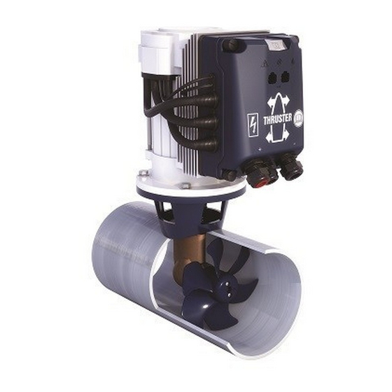
BOW PRO 'B' Series Thrusters
150 kgf - 180 kgf - 210 kgf - ø 250 mm
Copyright © 2020 Vetus b.v. Schiedam Holland
NEDERLANDS
ENGLISH
DEUTSCH
FRANÇAIS
ESPAÑOL
ITALIANO
DANSK
SVENSKA
NORSK
SUOMEKSI
POLSKI
Installasjonsinstrukser
Asennusohje
Instrukcja instalacji
9
21
33
45
57
69
81
93
105
117
129
020809.04
Werbung
Inhaltsverzeichnis

Verwandte Anleitungen für Vetus BOW PRO B Thruster Serie


Inhaltszusammenfassung für Vetus BOW PRO B Thruster Serie
- Seite 1 Instructions d’installation Monteringsinstruktioner Instrukcja instalacji Instrucciones de instalación Installation instructions BOW PRO 'B' Series Thrusters BOWB150 - BOWB180 - BOWB210 150 kgf - 180 kgf - 210 kgf - ø 250 mm Copyright © 2020 Vetus b.v. Schiedam Holland 020809.04...
- Seite 4 Zur Wartung vgl . das „Wartungs- und Garantiebuch“ . remédier aux pannes éventuelles . Consulter le « Manuel d'entretien et de garantie » pour effectuer les travaux de maintenance . vetus® Installation instructions BOW PRO Series Thrusters: BOWB150 - BOWB180 - BOWB210 020809.04...
-
Seite 33: Sicherheitsbestimmungen
. chtunG Überprüfen Sie mögliche Lecks sofort, wenn das Schiff sich wieder im Wasser befindet . Sorgen Sie dafür, daß dem Schiffseigner die Gebrauchsanleitung bereitgestellt wird . vetus® Installation instructions BOW PRO Series Thruster: BOWB150 - BOWB180 - BOWB210 020809.04... -
Seite 34: Einbauhinweise
Wir raten davon ab, 2 Bugschrauben in einem (1) Tunnelrohr zung in jedem Fall notwendig. einzu-bauen. Eine Verdoppelung der Antriebskraft wird dadurch - Der Elektromotor soll immer oberhalb des höchstmöglichen Bil- nicht erreicht! genwasserniveaus aufgestellt werden. vetus® Installation instructions BOW PRO Series Thrusters: BOWB150 - BOWB180 - BOWB210 020809.04... -
Seite 35: Übergang Vom Tunnelrohr Zum Schiffsrumpf
Herzlinie des Muschels mit der zu erwartenden Form der Bugwelle zusammenfällt. - Die Stäbe müssen so angebracht werden, dass sie senkrecht zu der zu erwartenden Bugwellenform stehen. vetus® Installation instructions BOW PRO Series Thruster: BOWB150 - BOWB180 - BOWB210 020809.04... -
Seite 36: Anbringen Vom Tunnelrohr
• Danach gegebenenfalls ein be- rend. Die Schrauben und der Schaft wuchsverhinderndes Mittel auftra- müssen jedoch noch mit Isolations- gen. material, z.B. Nylonbuchsen, versehen werden. vetus® Installation instructions BOW PRO Series Thrusters: BOWB150 - BOWB180 - BOWB210 020809.04... -
Seite 37: Einbau
30 - 35 Nm Grease chtunG Unmittelbar nach dem Stapellauf des Schiffes auf mögliche Lecks prüfen *) Ein geeignetes Fett ist das VETUS „Shipping Grease“, Artikelcode: VSG. vetus® Installation instructions BOW PRO Series Thruster: BOWB150 - BOWB180 - BOWB210 020809.04... -
Seite 38: Endmontage
Welle des Elektromotors mitgenommen wird. 20 - 25 Nm *) Ein geeignetes Fett ist das VETUS „Shipping Grease“, Artikelcode: VSG. Molykote® G-n plus vetus® Installation instructions BOW PRO Series Thrusters: BOWB150 - BOWB180 - BOWB210 020809.04... -
Seite 39: Stromversorgung
Der BATSW250 ist auch in 2-poliger Ausführung erhältlich, Vetus Ar- (6 - 7 ft-lbf ) (6 - 7 ft-lbf ) tikel-Nr. BATSW250T. 24 Volt 48 Volt Zu Anschlussskizzen vgl . auch Seite 148 . vetus® Installation instructions BOW PRO Series Thruster: BOWB150 - BOWB180 - BOWB210 020809.04... -
Seite 40: Hauptnetzsicherung
Bedienelemente angeschlossen sind. dienfeld vorhanden sein. Am einen Ende dieser Leitung muss die CAN-Bus-Versorgung (5), - BPPJA - BPPPA am anderen Ende der Abschluss (8) angeschlossen werden! vetus® Installation instructions BOW PRO Series Thrusters: BOWB150 - BOWB180 - BOWB210 020809.04... -
Seite 41: Kontrolle/Probelauf Und Konfigurieren Der Bedientafeln
Richtung wie der Joystick bewegt, kann das auf die Weise geändert werden, wie in 6.7 angegeben. Die dargestellten Arbeiten müssen auf JEDEM installierten Bedien- feld durchgeführt werden . vetus® Installation instructions BOW PRO Series Thruster: BOWB150 - BOWB180 - BOWB210 020809.04... -
Seite 42: Konfigurieren Eines Bedienelements Für Das Bedienen Eines Bug- Oder Heckstrahlruders
Bei einer Bug- und Heckstrahlruderbedienfleder muss an der- Die Einstellungen bleiben erhalten, wenn die Netzspannung selben Helmstation die eingegebene Helmstationnummer ausgeschaltet wird! identisch sein . vetus® Installation instructions BOW PRO Series Thrusters: BOWB150 - BOWB180 - BOWB210 020809.04... -
Seite 43: Konfigurieren Eines Bedienelements Für Den Steuerstand, An Dem Sich Das Bedienfeld Befindet
Bei einer Bug- und Heckstrahlruderbedienfleder muss an der- Die Einstellungen bleiben erhalten, wenn die Netzspannung selben Helmstation die eingegebene Helmstationnummer ausgeschaltet wird! identisch sein . vetus® Installation instructions BOW PRO Series Thruster: BOWB150 - BOWB180 - BOWB210 020809.04... -
Seite 44: Änderung Der Schubrichtung
Ein-/Aus-Taste, um einmal nach rechts. Nun geht die die Einstellung zu be- rote LED links oben an und be- stätigen stätigt, dass die Schubrichtung geändert ist. vetus® Installation instructions BOW PRO Series Thrusters: BOWB150 - BOWB180 - BOWB210 020809.04... -
Seite 143: Aansluitschema's
Magistrala CAN to łańcuch, do którego dołączony jest ster strumie- niowy i panele. Na jednym końcu łańcucha musi być podłączony zasilacz (5), a ter- minator (8) musi być podłączony na drugim końcu! vetus® Installation instructions BOW PRO Series Thruster: BOWB150 - BOWB180 - BOWB210 020809.04... - Seite 144 Alimentazione CAN-bus 6 Control voltage fuse Fusible régulateur de tension Fusibile della tensione di comando 7 Connection cable Câble de raccordement Cavo di collegamento 8 Terminator Terminateur Terminatore vetus® Installation instructions BOW PRO Series Thrusters: BOWB150 - BOWB180 - BOWB210 020809.04...
- Seite 145 Panel sterowania pędnik dziobowy 4 Peräpotkurin ohjauspaneeli Panel sterowania pędnik rufowy 5 CAN-väylän syöttö Zasilanie magistrali CAN 6 Ohjausjännitteen sulake Bezpiecznik sterowania 7 Kytkentäkaapeli Kabel przyłączeniowy 8 Terminaattori Terminator vetus® Installation instructions BOW PRO Series Thruster: BOWB150 - BOWB180 - BOWB210 020809.04...
- Seite 146 Alimentazione CAN-bus 6 Control voltage fuse Fusible régulateur de tension Fusibile della tensione di comando 7 Connection cable Câble de raccordement Cavo di collegamento 8 Terminator Terminateur Terminatore vetus® Installation instructions BOW PRO Series Thrusters: BOWB150 - BOWB180 - BOWB210 020809.04...
- Seite 148 Batteria 3 Fusible principal Fusible principal Fusibile principale 4 Interrupteur principal Interruptor principal Interruttore principale 5 Dynamo Dínamo Dinamo 6 Démarreur Motor de arranque Motorino di avviamento vetus® Installation instructions BOW PRO Series Thrusters: BOWB150 - BOWB180 - BOWB210 020809.04...
- Seite 149 1 Potkurin (tai peräpotkurin) liitäntärasia Skrzynka przyłączeniowa pędnika dziobowego (lub pędnik rufowy) 2 Akku Bateria 3 Pääsulake Główny bezpiecznik 4 Pääkatkaisin Główny przełącznik 5 Dynamo Dynamo 6 Käynnistysmoottori Rozrusznik vetus® Installation instructions BOW PRO Series Thruster: BOWB150 - BOWB180 - BOWB210 020809.04...
- Seite 150 Batteria 3 Fusible principal Fusible principal Fusibile principale 4 Interrupteur principal Interruptor principal Interruttore principale 5 Dynamo Dínamo Dinamo 6 Démarreur Motor de arranque Motorino di avviamento vetus® Installation instructions BOW PRO Series Thrusters: BOWB150 - BOWB180 - BOWB210 020809.04...
- Seite 151 1 Potkurin (tai peräpotkurin) liitäntärasia Skrzynka przyłączeniowa pędnika dziobowego (lub pędnik rufowy) 2 Akku Bateria 3 Pääsulake Główny bezpiecznik 4 Pääkatkaisin Główny przełącznik 5 Dynamo Dynamo 6 Käynnistysmoottori Rozrusznik vetus® Installation instructions BOW PRO Series Thruster: BOWB150 - BOWB180 - BOWB210 020809.04...
-
Seite 152: Accucapaciteit, Accukabels
285,1 - 359,9 ft 2 x 120 mm 2 x AWG 0000 109,7 - 118 m 359,9 - 387,1 ft 2 x 150 mm 2 x AWG 300 MCM vetus® Installation instructions BOW PRO Series Thrusters: BOWB150 - BOWB180 - BOWB210 020809.04...