Vetus BOWA0401 Installationshandbuch
Inhaltsverzeichnis
Verfügbare Sprachen
Verfügbare Sprachen
Quicklinks
Installatiehandleiding
Installationshandbuch
Manuel d' installation
Manual de instalación
Manuale d'installazione
Installationsvejledning
Installationsmanual
Installation manual
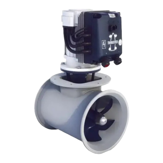
BOW PRO 'A' Series Thrusters
BOWA0401
40 kgf - ø 140 mm - 12 V
Copyright © 2022 VETUS Schiedam Holland
NEDERLANDS
ENGLISH
DEUTSCH
FRANÇAIS
ESPAÑOL
ITALIANO
DANSK
SVENSKA
NORSK
SUOMEKSI
POLSKI
Installasjons handbook
Asennusopas
Instrukcja instalacji
7
16
25
34
43
52
61
70
79
88
97
020817.01
Inhaltsverzeichnis
Fehlerbehebung

Verwandte Anleitungen für Vetus BOWA0401


Inhaltszusammenfassung für Vetus BOWA0401
- Seite 2 Sørg for at skipets eier kan disponere over bruksanvisningen. Käyttöohje tulee olla alusta käyttävien henkilöiden käytettävissä. Upewnić się, że użytkownik statku jest zaopatrzony w instrukcję obsługi. BOWA0401 - 40 kgf - ø 140 mm - 12 Volt Installation manual BOW PRO Series Thrusters: BOWA0401 020817.01...
-
Seite 3: Inhaltsverzeichnis
..... Hauptabmessungen ... Installation manual BOW PRO Series Thruster: BOWA0401 020817.01... -
Seite 25: Sicherheitsbestimmungen
Der Raum, in dem die Bugschraube installiert wird, und der Einleitung Raum, in dem der Akku installiert wird, muss trocken und gut belüftet sein. Diese Einbauanleitung enthält Richtlinien für den Einbau der VETUS Bugschraube und/oder Heckstrahlruder aus der BOW PRO-Serie, Typ „BOWA0401“. chtunG Überprüfen Sie mögliche Lecks sofort, wenn das Schiff sich... -
Seite 26: Einbauhinweise
Wir raten davon ab, 2 Bugschrauben in einem (1) Tunnelrohr zung in jedem Fall notwendig. einzu-bauen. Eine Verdoppelung der Antriebskraft wird dadurch - Der Elektromotor soll immer oberhalb des höchstmöglichen Bil- nicht erreicht! genwasserniveaus aufgestellt werden. Installation manual BOW PRO Series Thrusters: BOWA0401 020817.01... -
Seite 27: Übergang Vom Tunnelrohr Zum
15º aufgenommen werden, daß die Herzlinie des Muschels mit der zu erwartenden Form der Bugwelle zusammenfällt. - Die Stäbe müssen so angebracht werden, dass sie senkrecht zu der zu erwartenden Bugwellenform stehen. Installation manual BOW PRO Series Thruster: BOWA0401 020817.01... -
Seite 28: Anbringen Vom Tunnelrohr
ACHTUNG: Die mitgelieferten Dich- tungen sind bereits elektrisch isolie- • Danach gegebenenfalls ein be- rend. Die Schrauben und der Schaft wuchsverhinderndes Mittel auftra- müssen jedoch noch mit Isolations- gen. material, z.B. Nylonbuchsen, versehen werden. Installation manual BOW PRO Series Thrusters: BOWA0401 020817.01... -
Seite 29: Einbau
• Die Bolzengewinden zuerst mit ‘outboard gear grease’ *) einfetten. 12 - 15 Nm Outboard Gear Grease chtunG Unmittelbar nach dem Stapellauf des Schiffes auf mögliche Lecks prüfen *) Ein geeignetes Fett ist das VETUS „Shipping Grease“, Artikelcode: VSG. Installation manual BOW PRO Series Thruster: BOWA0401 020817.01... -
Seite 30: Endmontage
• Als erste Probe den Propeller von Hand drehen; das sollte rei- bungslos geschehen, als zugleich die Welle des Elektromotors mitgenommen wird. 20 - 25 Nm Molykote® G-n plus *) Ein geeignetes Fett ist das VETUS „Shipping Grease“, Artikelcode: VSG. Installation manual BOW PRO Series Thrusters: BOWA0401 020817.01... -
Seite 31: Stromversorgung
Akkuleistung wird die Bugschraube noch besser funktionieren! Achten Sie darauf, dass beim Anschließen der elektrischen Ka- Wir empfehlen wartungsfreie Schiffsakkus von VETUS. Sie sind in fol- bel keine anderen elektrischen Teile gelöst werden. genden Größen lieferbar: 55 Ah, 70 Ah, 90 Ah, 108 Ah, 120 Ah, 143 Ah, 165 Ah, 200 Ah und 225 Ah. -
Seite 32: Anschließen Von Can-Bus (Steuerstrom)-Kabeln
Situationen sowie Korrosionsprobleme, sondern • Ist der Stecker, der von der Platine der oberen Abdeckung zur auch Fehlermeldungen im CAN-Bus-System. Motorsteuerung des Strahlruders führt, fest und sind alle Stecker- stifte richtig angeschlossen? (eingerastet?) Installation manual BOW PRO Series Thrusters: BOWA0401 020817.01... -
Seite 33: Technische Daten
Aussenmaß 152,4 mm, Wandstärke 5 mm Material Aluminium, 6060 oder 6062 (AlMg1SiCu) Gewicht Ohne Rohr 31 kg S2 „t“ min. Einschaltdauer „t“ Min. kontinuierlich oder max. „t“ Min. pro Stunde bei maximaler Leistung. Installation manual BOW PRO Series Thruster: BOWA0401 020817.01... - Seite 112 Fusible principal Fusibile principale 4 Interrupteur principal Interruptor principal Interruttore principale 5 Dynamo Dínamo Dinamo 6 Démarreur Motor de arranque Motorino di avviamento 7 Pont à diodes Puente de diodo Ponticello diodo Installation manual BOW PRO Series Thrusters: BOWA0401 020817.01...