Dimplex SI 26TU Montage- Und Gebrauchsanweisungen
Sole-wasser-wärmepumpe fur innenaufstellung
Verfügbare Sprachen
Verfügbare Sprachen
Quicklinks
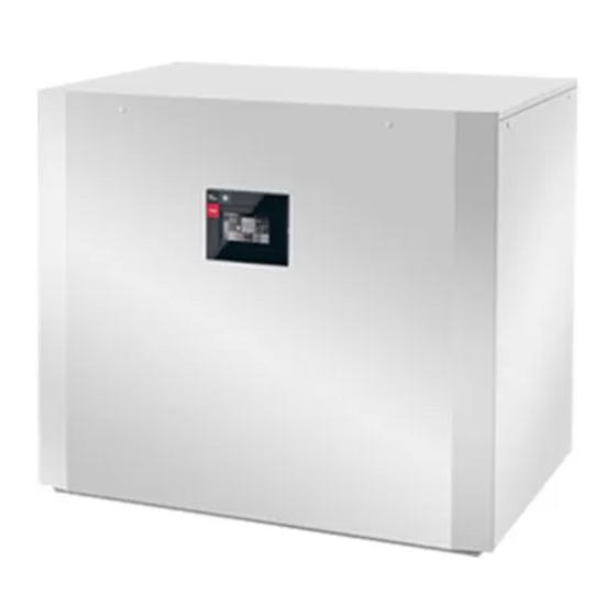
SI 26TU
SI 35TU
Montage- und
Gebrauchsanweisung
Sole-Wasser-
Wärmepumpe
für Innenaufstellung
Bestell-Nr. | Order no. | No de commande: 452237.66.48a
Installation and
Operating Instruction
Brine-to-Water
Heat Pump for
Indoor Installation
Glen
Dimplex
Deutschland
Instuctions d'installation
et d'utilisation
Pompe à chaleur
eau glycolée-eau pour
installation intérieure
DE | EN | FR · FD 0108
Dimplex
Kapitel
Fehlerbehebung

Verwandte Anleitungen für Dimplex SI 26TU


Inhaltszusammenfassung für Dimplex SI 26TU
- Seite 1 Glen Dimplex Deutschland Dimplex SI 26TU SI 35TU Montage- und Installation and Instuctions d‘installation Gebrauchsanweisung Operating Instruction et d‘utilisation Sole-Wasser- Brine-to-Water Pompe à chaleur Wärmepumpe Heat Pump for eau glycolée-eau pour für Innenaufstellung Indoor Installation installation intérieure Bestell-Nr. | Order no. | No de commande: 452237.66.48a...
-
Seite 3: Inhaltsverzeichnis
SI 26TU - SI 35TU Deutsch Inhaltsverzeichnis Sicherheitshinweise............................DE-2 1.1 Symbole und Kennzeichnung............................DE-2 1.2 Bestimmungsgemäßer Gebrauch ..........................DE-2 1.3 Gesetzliche Vorschriften und Richtlinien.........................DE-2 1.4 Energiesparende Handhabung der Wärmepumpe ....................DE-2 Verwendungszweck der Wärmepumpe ....................DE-2 2.1 Anwendungsbereich...............................DE-2 2.2 Arbeitsweise..................................DE-2 Grundgerät..............................DE-3 Zubehör .................................DE-3 4.1 Anschlussflansche................................DE-3 4.2 Fernbedienung..................................DE-3... -
Seite 4: Sicherheitshinweise
Deutsch SI 26TU - SI 35TU ACHTUNG! Sicherheitshinweise Für den Betrieb und die Wartung einer Wärmepumpe sind die rechtlichen Anforderungen des Landes einzuhalten, in dem 1.1 Symbole und Kennzeichnung Wärmepumpe betrieben wird. nach Kältemittelfüllmenge ist die Dichtheit der Wärmepumpe in Besonders wichtige Hinweise sind in dieser Anleitung mit ACH- regelmäßigen Abständen durch entsprechend geschultes... -
Seite 5: Grundgerät
SI 26TU - SI 35TU Deutsch Grundgerät Zubehör Das Grundgerät besteht aus einer anschlussfertigen Wärme- 4.1 Anschlussflansche pumpe für Innenaufstellung mit Blechgehäuse, Schaltkasten und integriertem Wärmepumpenmanager. Der Kältekreis ist Durch den Einsatz der flachdichtenden Anschlussflansche „hermetisch geschlossen“ und enthält das vom Kyoto-Protokoll kann das Gerät optional auf Flanschanschluss umgestellt wer-... -
Seite 6: Aufstellung
Deutsch SI 26TU - SI 35TU Zum Anheben des Gerätes ohne Palette sind die seitlich im Aufstellung Rahmen vorgesehenen Bohrungen zu benutzen. Die seitlichen Verkleidungsbleche sind dabei abzunehmen. Als Tragehilfe 6.1 Allgemeine Hinweise kann ein handelsübliches Rohr dienen. Nach dem Transport ist die Transportsicherung im Gerät am Die Sole/Wasser-Wärmepumpe muss in einem frostfreien und... -
Seite 7: Heizungsseitiger Anschluss
SI 26TU - SI 35TU Deutsch 7.2 Heizungsseitiger Anschluss Mindestheizwasserdurchsatz Der Mindestheizwasserdurchsatz der Wärmepumpe ist in jedem Betriebszustand der Heizungsanlage sicherzustellen. ACHTUNG! Dieses kann z.B. durch Installation eines doppelt differenz- Vor Anschluss der Wärmepumpe Heizungsanlage spülen. drucklosen Verteilers erreicht werden. -
Seite 8: Temperaturfühler
Deutsch SI 26TU - SI 35TU 7.4 Temperaturfühler 7.4.2 Montage des Außentemperaturfühlers Folgende Temperaturfühler sind bereits eingebaut bzw. müs- sen zusätzlich montiert werden: Der Temperaturfühler muss so angebracht werden, dass sämt- liche Witterungseinflüsse erfasst werden und der Messwert Außentemperatur (R1) beigelegt (NTC-2) nicht verfälscht wird. -
Seite 9: Verteilsystem Hydraulik
SI 26TU - SI 35TU Deutsch 7.4.4 Verteilsystem Hydraulik Zuführung Signalleitungen Kompaktverteiler und doppelt differenzdruckloser Verteiler fungieren als Schnittstelle zwischen der Wärmepumpe, dem Heizungsverteilsystem, dem Pufferspeicher und evtl. auch dem Zuführungen Lastleitungen Warmwasserspeicher. Dabei wird statt vieler Einzelkomponen- ten ein kompaktes System verwendet, um die Installation zu vereinfachen. -
Seite 10: Anschluss Von Elektronisch Geregelten Umwälzpumpen
Deutsch SI 26TU - SI 35TU Die Heizungsumwälzpumpe (M13) wird über den Kontakt Inbetriebnahme N1-J13/NO5 angesteuert. Anschlusspunkte für die Pumpe sind X2/M13 und X2/N. Bei Verwendung von Pumpen, die 8.1 Allgemeine Hinweise die Schaltkapazität des Ausgangs übersteigen muss ein Koppelrelais zwischengeschaltet werden. -
Seite 11: Pflege / Reinigung
SI 26TU - SI 35TU Deutsch Pflege / Reinigung 10 Störungen / Fehlersuche Diese Wärmepumpe ist ein Qualitätsprodukt und sollte stö- 9.1 Pflege rungsfrei arbeiten. Tritt dennoch eine Störung auf, wird diese im Display des Wärmepumpenmanagers angezeigt. Schlagen Sie Um Betriebsstörungen durch Schmutzablagerungen in den dazu auf der Seite Störungen und Fehlersuche in der Montage-... -
Seite 12: Geräteinformation
Deutsch SI 26TU - SI 35TU 12 Geräteinformation Typ- und Verkaufsbezeichnung SI 26TU SI 35TU Bauform Wärmequelle Sole Sole Ausführung Universal Universal Regler integriert integriert Wärmemengenzähler integriert integriert Aufstellungsort Innen Innen Leistungsstufen Einsatzgrenzen 20 bis 62 ±2 20 bis 62 ±2 Heizwasser-Vorlauf °C... - Seite 13 SI 26TU - SI 35TU Deutsch Entspricht den europäischen Sicherheitsbestimmungen Sonstige Ausführungsmerkmale Wasser im Gerät gegen Einfrieren geschützt max. Betriebsüberdruck (Wärmequelle/Wärmesenke) Heizleistung / Leistungszahl EN 14511 EN 14511 Wärmeleistung / Leistungszahl Leistungsstufe bei B-5 / W45 kW / --- 11,5 / 3,6...
-
Seite 14: Produktinformationen Gemäß Verordnung (Eu) Nr.813/2013, Anhang Ii, Tabelle 2
Kontakt Glen Dimplex Deutschland GmbH, Am Goldenen Feld 18, 95326 Kulmbach (*) Für Heizgeräte und Kombiheizgeräte mit Wärmepumpe ist die Wärmenennleistung Prated gleich der Auslegungslast im Heizbetrieb Pdesingh und die Wärmenennleistung eines Zusatzheizgerätes Psup gleich der zusaätzlichen Heizleistung sup(Tj ). - Seite 15 Kontakt Glen Dimplex Deutschland GmbH, Am Goldenen Feld 18, 95326 Kulmbach (*) Für Heizgeräte und Kombiheizgeräte mit Wärmepumpe ist die Wärmenennleistung Prated gleich der Auslegungslast im Heizbetrieb Pdesingh und die Wärmenennleistung eines Zusatzheizgerätes Psup gleich der zusaätzlichen Heizleistung sup(Tj ).
-
Seite 16: Garantieurkunde
Deutsch SI 26TU - SI 35TU Eine Verlängerung der Garantie auf 60 Monate oder mehr für Hei- 14 Garantieurkunde zungs-Wärmepumpen und zentrale Wohnungslüftungsgeräte ab der ersten Inbetriebsetzung, spätestens jedoch 6 Monate nach Glen Dimplex Deutschland Kaufdatum, wird gemäß den nachfolgenden Bedingungen gewährt (Heizungs-Wärmepumpen, Zentrale Wohnungslüftungsgeräte) - Seite 30 English SI 26TU - SI 35TU EN-14 452237.66.48a · FD 0108 www.glendimplex.de...
- Seite 44 Français SI 26TU - SI 35TU FR-14 452237.66.48a · FD 0108 www.glendimplex.de...
-
Seite 45: Anhang / Appendix / Annexes
Anhang / Appendix / Annexes Maßbilder / Dimension Drawings / Schémas cotés ................A-II 1.1 Maßbild / Dimension Drawing / Schéma coté SI 26TU - SI 35TU ..............A-II Diagramme / Diagrams / Diagrammes ....................A-III 2.1 Kennlinien / Characteristic Curves / Courbes caractéristiques SI 26TU............A-III 2.2 Kennlinien / Characteristic Curves / Courbes caractéristiques SI 35TU............ -
Seite 49: Einsatzgrenzendiagramm / Operating Limits Diagram / Diagramme Des Seuils D'utilisation
SI 26TU - SI 35TU Anhang · Appendix · Annexes 2.3 Einsatzgrenzendiagramm / Operating limits diagram / Diagramme des seuils d'utilisation Wasseraustritt (+/- 2 K) Water outlet (+/- 2 K) Sortie d'eau (+/- 2 K) Heizwasserdurchfluss min / max water flow rate min / max Débit d'eau de chauffage min / max... -
Seite 55: Legende / Legend / Légende Si 26Tu
SI 26TU - SI 35TU Anhang · Appendix · Annexes 3.6 Legende / Legend / Légende SI 26TU Brücke EVU-Sperre, muss eingelegt werden, wenn Utility block (EVU) bridge must be inserted if no Pont de blocage de la société d'électricité, à... - Seite 56 Anhang · Appendix · Annexes SI 26TU - SI 35TU Sanftanlaufsteuerung M1 Soft start control M1 Commande de démarrage progressif M1 Sanftanlaufsteuerung M3 Soft start control M3 Commande de démarrage progressif M3 Bedienteil Control panel Unité de commande N17* pCOe-Modul...
-
Seite 62: Legende / Legend / Légende Si 35Tu
Anhang · Appendix · Annexes SI 26TU - SI 35TU 3.12 Legende / Legend / Légende SI 35TU Brücke EVU-Sperre, muss eingelegt werden, wenn Utility block (EVU) bridge must be inserted if no Pont de blocage de la société d'électricité, à... - Seite 63 SI 26TU - SI 35TU Anhang · Appendix · Annexes Sanftanlaufsteuerung M1 Soft start control M1 Commande de démarrage progressif M1 Sanftanlaufsteuerung M3 Soft start control M3 Commande de démarrage progressif M3 Bedienteil Control panel Unité de commande N17* pCOe-Modul...
-
Seite 64: Hydraulisches Einbindungsschema / Hydraulic Integration Diagram / Schéma D'intégration Hydraulique
Anhang · Appendix · Annexes SI 26TU - SI 35TU 4 Hydraulisches Einbindungsschema / Hydraulic integration diagram / Schéma d'intégration hydraulique 4.1 Monovalente Wärmepumpenanlage mit 3 Heizkreisen und Warmwasserbereitung / Monovalent heat pump system with three heating circuits and domestic hot water preparation / Installation monovalente de pompe à... -
Seite 65: Bivalente Wärmepumpenanlage Mit Zwei Heizkreisen Und Warmwasserbereitung / Bivalent System With Two Heating Circuits And Domestic Hot Water Preparation / Installation Bivalente Avec Deux Circuits De Chauffage Et Production D´eau Chaude Sanitaire
SI 26TU - SI 35TU Anhang · Appendix · Annexes 4.2 Bivalente Wärmepumpenanlage mit zwei Heizkreisen und Warmwasserbereitung / Bivalent system with two heating circuits and domestic hot water preparation / Installation bivalente avec deux circuits de chauffage et production d´eau chaude sanitaire www.glendimplex.de... -
Seite 67: Konformitätserklärung / Declaration Of Conformity / Déclaration De Conformité
SI 26TU - SI 35TU Anhang · Appendix · Annexes 5 Konformitätserklärung / Declaration of Conformity / Déclaration de conformité Die aktuelle CE-Konformitätserklärung finden sie als Download unter: You can find and download the current CE conformity declaration at: Vous pouvez télécharger la déclaration de conformité CE actuelle sous : https://glendimplex.de/si26tu... - Seite 68 Glen Dimplex Deutschland Verkauf und Planung Service und Technischer Support Zentrale Projektierung Kundendienst, Technische Unter- stützung und Ersatzteile Glen Dimplex Deutschland GmbH Projektierung Ihrer Projekte und Hilfestellung vor und nach Installation Am Goldenen Feld 18 Planungsunterstützung. Ihrer Geräte D-95326 Kulmbach...