
Verwandte Anleitungen für Stahl SolConex 8570/11


Inhaltszusammenfassung für Stahl SolConex 8570/11
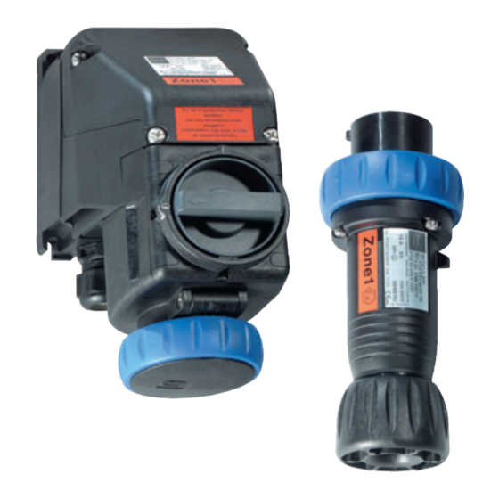
- Seite 1 Betriebsanleitung/Operating Instructions Wandsteckdose, Stecker Wall-mounted Socket, Plug > 8570/11, 8570/12...
- Seite 3 Betriebsanleitung Wandsteckdose, Stecker > 8570/11, 8570/12...
-
Seite 4: Inhaltsverzeichnis
Installation ......................10 Inbetriebnahme ....................12 Betrieb .........................12 Wartung .......................13 Zubehör und Ersatzteile ..................14 Baumuster-Prüfbescheinigung (1. Seite) ............15 Konformitätserklärung ..................16 Allgemeine Angaben 2.1 Hersteller R. STAHL Schaltgeräte GmbH Am Bahnhof 30 D-74638 Waldenburg Telefon: +49 7942 943-0 Telefax: +49 7942 943-4333 Internet: www.stahl.de 2.2 Angaben zur Betriebsanleitung... -
Seite 5: Allgemeine Sicherheitshinweise
Allgemeine Sicherheitshinweise Allgemeine Sicherheitshinweise 3.1 Sicherheitshinweise für Montage- und Bedienpersonal Die Betriebsanleitung enthält grundlegende Sicherheitshinweise, die bei Aufstellung, Betrieb und Wartung zu beachten sind. Nichtbeachtung hat eine Gefährdung für Personen, Anlage und Umwelt zur Folge. WARNUNG Gefahr durch unbefugte Arbeiten am Gerät! Verletzungen und Sachschäden drohen. -
Seite 6: Normenkonformität
Vorgesehener Einsatzbereich 3.3 Normenkonformität Die Wandsteckdose 8570/11 und der Stecker 8570/12 entsprechen folgenden Bestimmungen und Normen: Richtlinie 94/9/EG EN 50014, EN 50018, EN 50019, EN 50020, EN 50281-1-1 IEC 60079-0, IEC 60079-1, IEC 60079-7, IEC 60079-11, IEC 61241-1 EC 60947-3, IEC 60947-4-1, IEC 60309, IEC 60529 Vorgesehener Einsatzbereich Die Wandsteckdose 8570/11 und der Stecker 8570/12 sind explosionsgeschützte elektrische Betriebsmittel. -
Seite 7: Technische Daten
Technische Daten Technische Daten Steckdose 8570/11 (16 A) Explosionsschutz E II 2 G EEx ed IIC T6 Gasexplosionsschutz E II 2 D IP 66 T80°C Staubexplosionsschutz E II 2 G EEx ed [ia] IIC T6 Sonderausführung mit eigensicheren Hilfskontakten Bescheinigungen Gasexplosionsschutz PTB 03 ATEX 1227 Staubexplosionsschutz... - Seite 8 Technische Daten Anschlussklemmen 2 x 0,5 mm ... 2,5 mm eindrähtig/feindrähtig Hilfskontakte Leitungseinführungen Klemmbereich 7 mm ... 17 mm Kabeldurchmesser Kabeleinführungen 1 x M 25 x 1,5 Leitungseinführung auch von oben oder von der Seite möglich (auftragsbedingt) optional: oben max. 2 x M 25x 1,5; wahlweise auch Verschlussstopfen oder metallische Einführungen Verschlussstopfen 1 x M 25 x 1,5...
- Seite 9 Technische Daten 8570/12-3.. 43,5 16 A, 2 P + ¿ 8570/12-4.. 16 A, 3 P + ¿ 8570/12-5.. 56,5 16 A, 3 P + N + ¿ 10337E00 8570/12-.. Anordnung der Schutzkontaktbuchse Position: Uhrzeit-Stellung, Ansicht: Vorderseite der Steckdose Beispiel: Uhrzeit-Stellung 06190E00 250 V = 6 h 02395E00...
-
Seite 10: Transport, Lagerung Und Entsorgung
Transport, Lagerung und Entsorgung Kennfarbe und Anordnung der Kontaktbuchsen und Klemmenbezeichnungen Polzahl Frequenz [Hz] Spannung [V] Kennfarbe Lage der Schutzkontakt- buchse 8570/..-3.. 50 - 60 110 - 130 gelb 2P + ø 50 - 60 200 - 250 blau hellgrau 50 - 60 480 - 500 schwarz... -
Seite 11: Montage
Montage Montage 7.1 Montage Wandsteckdose Typ 8570/11-... Bei freier Witterung das Gehäuse mit Schutzdach oder -wand ausrüsten. Gebrauchslage: Klappdeckel nach unten, Anschlussraum nach oben Wandsteckdose mit vier Schrauben in senkrechter Gebrauchslage an einer ebenen Wand befestigen. Die Befestigungsbohrungen sind als Langlöcher ausgebildet. Dadurch ist ein vertikaler und horizontaler Montageausgleich möglich. -
Seite 12: Installation
Installation Installation WARNUNG Gefahr durch spannungsführende Teile! Schwerste Verletzungen drohen. Alle Anschlüsse und Verdrahtungen spannungsfrei schalten. Anschlüsse gegen unbefugtes Schalten sichern. WARNUNG Explosionsgefahr Verletzungen und Sachschäden drohen. Durch geeignete Leiterauswahl sicherstellen, dass maximal zulässige Leitertemperaturen nicht überschritten werden. Bei Verwendung von Aderendhülsen diese gasdicht mit geeignetem Werkzeug aufbringen. - Seite 13 Installation Installation Hilfskontakte 11202E00 Gehäuse öffnen. Kabel durch Kabeleinführung in Anschlussraum führen. Schraubenlose Klemmen mit Schraubendreher entriegeln (2) (Schneide 06 x 3,5 Form A nach DIN 5264 bzw. ISO 2380-1). Leitungen in entsprechende schraubenlose Klemmen einführen und festklemmen (3). Die abisolierten Leitungsenden müssen sich vollständig in der Klemme befinden. Leitungen ausrichten (Klemmstellen dürfen nicht unter Zug stehen).
-
Seite 14: Inbetriebnahme
10.1 Betrieb Wandsteckdose Typ 8570/11-... Die Wandsteckdose ist nur bei eingestecktem Stecker schaltbar. Bei gezogenem Stecker Klappdeckel mit dem Bajonettring verschließen. Es dürfen ausschließlich Stecker vom Typ 8570/12 und 8575/12 der Fa. R. STAHL verwendet werden. 10.2 Betrieb Stecker Typ 8570/12-... -
Seite 15: Wartung
Wartung 11 Wartung WARNUNG Gefahr durch spannungsführende Teile! Schwerste Verletzungen drohen. Alle Anschlüsse und Verdrahtungen spannungsfrei schalten. Anschlüsse gegen unbefugtes Schalten sichern. WARNUNG Gefahr durch defekte Schaltkontakte! Verletzungen und Sachschäden drohen. Nach jedem Kurzschluss im Hauptstromkreis des Schalters den kompletten Steckdosenflansch austauschen, da der Zustand der Schaltkontakte bei hermetisch abgeschlossenen Betriebsmitteln nicht überprüft werden kann. -
Seite 16: Zubehör Und Ersatzteile
Zubehör und Ersatzteile 12 Zubehör und Ersatzteile Benennung Abbildung Beschreibung Bestellnummer Verschlussstopfen 8290/3-M 25 x 1,5 1 Stück 8290009590 04840E00 Hilfskontakte 1 Schließer 8570802760 1 Öffner 8570801760 1 Schließer, Goldkontakt 8570804760 10341E00 1 Öffner, Goldkontakt 8570803760 Schutzkappen für Stecker 16 A 3-polig 8570001140 nicht für Ausführung Kleinspannung... -
Seite 17: Baumuster-Prüfbescheinigung (1. Seite)
Baumuster-Prüfbescheinigung (1. Seite) 13 Baumuster-Prüfbescheinigung (1. Seite) 8570601300 Wandsteckdose, Stecker S-BA-8570/11/12-03-de-31/01/2007 8570/11, 8570/12... -
Seite 18: Konformitätserklärung
Konformitätserklärung 14 Konformitätserklärung Wandsteckdose, Stecker 8570601300 8570/11, 8570/12 S-BA-8570/11/12-03-de-31/01/2007... - Seite 19 Operating Instructions Wall-Mounted Socket, Plug > 8570/11, 8570/12...
-
Seite 20: General Information
Operation ......................12 Maintenance ......................13 Accessories and Spare Parts ................14 Type examination certificate (Page 1) ..............15 Declaration of Conformity ..................16 General Information 2.1 Manufacturer R. STAHL Schaltgeräte GmbH Am Bahnhof 30 D-74638 Waldenburg Telephone: +49 7942 943-0 Fax: +49 7942 943-4333 Internet: www.stahl.de... -
Seite 21: General Notes Regarding Safety
General Notes Regarding Safety General Notes Regarding Safety 3.1 Safety instructions for installation and operating personnel The operating instructions contain fundamental notes regarding safety, which must be observed during installation, operation and maintenance. Non-observance can result in a hazard to persons, plant and environment. WARNING Risk due to unauthorised work being performed on the device! There is a risk of injury to persons and material damage. -
Seite 22: Conformity To Standards
Intended Area of Application 3.3 Conformity to Standards The wall-mounted socket 8570/11 and plug 8570/12 comply with the following directives and standards: Directive 94/9/EC EN 50014, EN 50018, EN 50019, EN 50020, EN 50281-1-1 IEC 60079-0, IEC 60079-1, IEC 60079-7, IEC 60079-11, IEC 61241-1 EC 60947-3, IEC 60947-4-1, IEC 60309, IEC 60529 Intended Area of Application The wall-mounted socket 8570/11 and plug 8570/12 are explosion protected electrical... -
Seite 23: Technical Data
Technical Data Technical Data Socket 8570/11 (16 A) Explosion protection E II 2 G EEx ed IIC T6 Gas explosion protection E II 2 D IP 66 T80°C Dust explosion protection E II 2 G EEx ed [ia] IIC T6 Special version with intrinsically safe auxiliary contacts... - Seite 24 Technical Data Aux. contact connection 2 x 0.5 mm ... 2.5 mm single wire/stranded copper terminals Cable entries Clamp size 7 mm ... 17 mm outer diameter Cable gland 1 x M 25 x 1.5 Cable entries are possible on the top or on the side wall (upon request) optional: top max.
- Seite 25 Technical Data Type 8570/12-3.. 43.5 16 A, 2 P + ø 8570/12-4.. 16 A, 3 P + ø 8570/12-5.. 56.5 16 A, 3 P + N + ø 10337E00 8570/12-.. Position of the protective earth (PE) contact Position: clock-hour position; View: front face of the socket Example: clock-hour position 06190E00 250 V = 6 o’clock...
-
Seite 26: Transport, Storage And Disposal
Transport, Storage and Disposal Contact layout and identification colour and terminal markings Number of poles Frequency [Hz] Voltage [V] Identification colour Position of the PE con- tact 8570/..-3.. 50 - 60 110 - 130 yellow 4 o’clock 2P + ø 50 - 60 200 - 250 blue... -
Seite 27: Assembly
Assembly Assembly 7.1 Assembly, wall-mounted socket, type 8570/11-... If exposed to the elements, the casing must be provided with a protective canopy or wall. Position for use: Hinged cover down, connection chamber up Fasten the wall-mounted socket, in a vertical position, to a flat wall, using four screws. The securing holes are elongated. -
Seite 28: Installation
Installation Installation WARNING Danger from live parts! Risk serious injury. All connections and wiring must be disconnected from the power supply. Secure the connections against unauthorised re-connection. WARNING Danger of explosion! There is a risk of injury to persons and material damage. Choose a suitable conductor, so that the maximum permissible conductor temperature is not exceeded. - Seite 29 Installation Installing auxiliary contacts 11202E00 Open the casing. Pass the cable through the cable entry into the connection chamber. Open the screwless clamps, using a screwdriver (2) (blade 06 x 3.5, shape A, in accordance with DIN 5262 or ISO 2380-1 respectively). Insert the conductors into the corresponding screwless terminals and clamp them (3).
-
Seite 30: Commissioning
When the plug is disconnected, lock the hinged cover with the bayonet ring. Only type 8570/12 and 8575/12 plugs, manufactured by R. STAHL, must be used. 10.2 Operation, plug, type 8570/12-... If a short circuit occurs in the circuit, to which the plug is connected, check the function of the plug. -
Seite 31: Maintenance
Maintenance 11 Maintenance WARNING Danger from live parts! Risk serious injury. All connections and wiring must be disconnected from the power supply. Secure the connections against unauthorised re-connection. WARNING Danger through defective switch contacts! There is a risk of injury to persons and material damage. The complete flange socket must always be replaced, if a short circuit occurs in the switch's main circuit, as the state of the switch contacts of hermetically sealed devices can not be determined. -
Seite 32: Accessories And Spare Parts
Accessories and Spare Parts 12 Accessories and Spare Parts Designation Illustration Description Ordering code Sealing plugs 8290/3-M 25 x 1.5 1 piece 8290009590 04840E00 Auxiliary contacts 1 NO 8570802760 1 NC 8570801760 1 NO, gold contact 8570804760 10341E00 1 NC, gold contact 8570803760 Protection caps for plug 16 A... -
Seite 33: Type Examination Certificate
Type examination certificate (Page 1) 13 Type examination certificate (Page 1) 8570601300 Wall-Mounted Socket, Plug S-BA-8570/11/12-03-en-31/01/2007 8570/11, 8570/12... -
Seite 34: Declaration Of Conformity
Declaration of Conformity 14 Declaration of Conformity Wall-Mounted Socket, Plug 8570601300 8570/11, 8570/12 S-BA-8570/11/12-03-en-31/01/2007... - Seite 36 8570601300 S-BA-8570/11/12-03-de/en-31/01/2007...