Commend WS 211V I DA Kurzanleitung
Intercom terminal mit induktionsschleife
Verfügbare Sprachen
Verfügbare Sprachen
Quicklinks
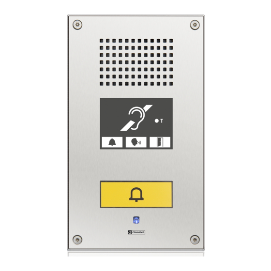
Intercom Terminal with Induction Loop WS 211V I DA
Extent of supply
ƒ Intercom Terminal
ƒ Induction Loop and mounting kit
Required Hardware
ƒ Power supply: 15 VDC - 26 VDC
ƒ Flush Mount Kit (WSFB 50V) or Surface Mount Kit (WSSH 50V)
Quick Start
Please follow the following instruction for the installation of the Intercom Terminal:
ƒ Open the WS Station - instruction see respective short reference
ƒ Mount the Induction Loop on the surface or flush mount box as shown in the following
picture
Mounting clip
Induction loop
Surface or Flush Mount Kit
ƒ Carry out the connection of the induction loop, signal input and power supply
ƒ Connect the loop cable (polarity does not matter) via the screw terminals as shown
in the following picture.
ƒ Connect power supply (15 VDC - 26 VDC) as shown in the following picture.
Note: If an external power supply is used for the terminal, it is possible to use this
power supply also for the Induction Loop Amplifier Module.
Note:
It is mandatory to install the induction loop on
the right side of the housing, as shown in the
connection diagram. Otherwise disturbing hum
may occur. For the installation use the attached
mounting clips and screws (in extent of supply).
BAD-
BAD-
MARK
MARK
BMK1
BMK1
Loop
MLC
Current
LED "Power"
+
- -
+
- -
1
1
BOC1
BOC1
1
1
C
C
O
O
B
B
External power supply
LINE IN
Output
15 V DC – 26 V DC
Induction loop
Expansion plug
for EB 2E2A
DC–
External power supply
15 V DC – 26 V DC
DC+
OUT 1
OUT 1 1
for fixing
cable straps
OUT 2
OUT 2
OUT 2
OUT 2
IP Uplink
(to Intercom Server)
ƒ Switch on the external power supply and check if the green "Power" LED illuminates!
ƒ The potentiometers "Level-Input" , "MLC" and "Loop Current" are preset at factory
delivery.
ƒ Test the performance of the system using a loop receiver or field strength meter and
adjust 'MLC' & 'LOOP CURRENT' to achieve acceptable performance - please consider
the respective norm!
ƒ Mount the Intercom Terminal - see short reference Surface / Flush Mount Kit.
2
2
C
C
O
O
B
B
BOC2
BOC2
Mounting clip
LED
"Adjust"
Induction loop
1
1
Surface or Flush Mount Kit
MUTE
GND
LINE–
LINE+

Verwandte Anleitungen für Commend WS 211V I DA


Inhaltszusammenfassung für Commend WS 211V I DA
- Seite 3 Intercom Terminal mit Induktionsschleife WS 211V I DA Lieferumfang ƒ Intercom Sprechstelle ƒ Induktionsschleife inkl. Montagematerial BOC2 BOC2 Benötigte Hardware ƒ Externe Spannungsversorgung: 15 VDC - 26 VDC Montageschelle ƒ Unterputzkit (WSFB 50x) oder Aufputzkit (WSSH 50x) Quick Start Bitte folgen Sie der folgenden Anleitung für die Installation der Intercom Sprechstelle:...
- Seite 4 Das Gerät darf nur von autorisiertem Fachpersonal installiert werden. Hinweis des Herstellers Dieses Gerät erfüllt die Anforderungen der EU-Richtlinie EMV-RL 2004/108/EG. Hierfür trägt das Gerät die CE-Kennzeichnung. Bitte bewahren Sie diese Beschreibung sorgfältig auf! Type: D-BZ-WS 211V I DA, Version: 1.1/0414...