Werbung
Quicklinks
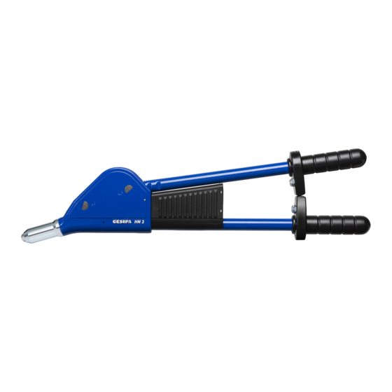
HN2
Bedien- und Wartungsanleitung mit Ersatzteilliste
Operation and service instructions incl. spare parts list
1. Arbeitsbereich:
Setzt Blindniete von 3,0 bis 6,4 mm Ø aller Werkstoffe, außer
PolyGrip
-Blindniete mit 6,4 mm Ø aus Edelstahl und G-Bulb-
®
Blindniete.
2. Ausrüstung/Zubehör
Mundstücke:
16/32 (in Arbeitsposition)
16/29, 16/36, 16/40, 16/45 (eingeschraubt in Handgriffe)
Nietdornauffangbehälter (in Arbeitsposition)
3. Mundstücks-Zuordnung
Ø
Nietschaft-
3 und 3,2
Alu, Cu, Stahl, Edelstahl, Stinox, Alu, PG-Alu, PG-Stahl
4
4
Stahl, CAP
4
Edelstahl, Stinox, PG-Stahl
4,8
CAP
5 und 4,8
5 und 4,8
5 und 4,8
Edelstahl, Stinox, PG-Stahl
6
6
6,4
6,4
4. Reinigen und Wechseln der Futterbacken
Wird der Nietdorn von den Futterbacken nicht gegriffen, so sind die
Futterbacken verschmutzt oder abgenutzt. Zum Wechseln der Futter-
backen wird zunächst die Stahlhülse und dann das Futtergehäuse
abgeschraubt. Die Druckbuchse und die Futterbacken sind aus dem
Futtergehäuse zu entnehmen. Vor Einbau die Futterbacken an ihren
Gleitflächen mit einem Ölfilm versehen. Der Einbau erfolgt in umgekehr-
ter Reihenfolge.
5. Auswechseln der Mundstücke
Die Mundstücke sind an der Schlüsselfläche gekennzeichnet und können
mittels Ringschlüssel (SW 12) ausgewechselt werden.
(Siehe auch 3. Mundstücks-Zuordnung)
6. Zusammenbau
Vor der Montage Gelenkstellen, Gleitflächen und Verzahnung fetten.
Bolzensicherung gefettet in die Lagerbohrung des Übersetzungsseg-
ments einsetzten. Übersetzungssegment wie abgebildet mit Zahnstange
in Eingriff bringen und in das Zangengehäuse einführen. Bolzensiche-
rung gefettet in die Lagerbohrung des Ritzels am Betätigungshebel ein-
setzen. Ritzelverzahnung mit Übersetzungssegment in Eingriff bringen.
Übersetzungseinheit sowie die Bolzensicherung positionieren und die
Bolzen einpressen. Abschlußblock mit Führungsrohr einführen und mit
Zylinderstift im Zangengehäuse verstiften. Futtermechanismus in der
abgebildeten Reihenfolge auf der Zahnstange montieren. Stahlhülse
sowie das gewählte Mundstück (16/..) aufschrauben. Auffangbehälter
auf Gehäusehebel klipsen und am Abschlußblock einrasten.
GESIPA Blindniettechnik GmbH
Nordendstraße 13-39
64546 Mörfelden-Walldorf
Germany
Hebel-Blindniet-Setzgerät
Lever riveting tool
Niet-Werkstoff
16/24
Alu, Cu
16/24
-Alu, CAP
-Cu, Alu, PG-Alu
16/27
®
®
16/29
-Alu, CAP
-Cu
16/29
®
®
Alu, PG-Alu
16/29
Stahl, Alu
16/32
16/36
Alu
16/36
Stahl
16/40
Alu, PG-Alu
16/40
Stahl, Alu
16/45
T +49 (0) 6105 962 0
F +49 (0) 6105 962 287
info@gesipa.com
www.gesipa.com
1. Working Capacity:
Blind rivets from 3.0 to 6.4 mm Ø all materials, except PolyGrip
rivets with 6.4 mm Ø made of stainless steel an G-Bulb blind rivets.
2. Equipment/ Accessories
Nosepieces:
16/32 (in working position)
16/29, 16/36, 16/40, 16/45 (screwed into grips)
Spent mandrel container (in position)
3. Nosepiece Chart
Rivet Ø
HN2
3 and 3.2
4
4
4
4.8
5 and 4.8
5 and 4.8
5 and 4.8
6
6
6.4
6.4
4. Cleaning and changing of jaws
If the jaws are not gripping or slipping on the rivet mandrel then the
jaws are being clogged or worn. To change the jaws unscrew head
first and then jaw housing. The jaw pusher and the
jaws can then be taken out. Before re-assembly the jaws should
be lubricated. Re- assemble by reversing above procedure
5. Changing Nosepieces
Nosepieces are marked at outside and can be exchanged by using a
wrench (SW12) according to the above nosepiece chart.
6. Re-Assembly
Before re-assembling all moving parts and contact points should be
lubricated. Insert lubricated bolt locking into bearing bore of gear secti-
on. Engage gear section with gear rack and put it into tool housing as
shown in the drawing. Insert lubricated bolt locking into bearing bore of
driving gear at operating lever. Engage driving gear with gear section.
Position transmission unit and bolt lockings and press the pivot bolts into
place. Insert end block with guiding tube into tool housing and secure it
with pin. Assemble jaw mechanism in sequence as shown in drawing to
gear rack. Screw on head together with the proper nosepiece (16/..).
Clip on spent mandrel container to housing lever and click it
onto end block.
Rivet material
Alu, Cu, Steel, Stainless steel, Stinox, Alu, PG-Alu, PG-Steel
Alu, Cu
Steel, CAP-Alu, CAP-Cu, Alu, PG-Alu
Stainless steel, Stinox, PG-Steel
CAP-Alu, CAP-Cu
Alu, PG-Alu
Steel, Alu
Stainless steel, Stinox, PG-Steel
Alu
Steel
Alu, PG-Alu
Steel, Alu
blind
®
HN2
16/24
16/24
16/27
16/29
16/29
16/29
16/32
16/36
16/36
16/40
16/40
16/45
Werbung

Verwandte Anleitungen für Gesipa HN2


Inhaltszusammenfassung für Gesipa HN2
- Seite 1 Zylinderstift im Zangengehäuse verstiften. Futtermechanismus in der abgebildeten Reihenfolge auf der Zahnstange montieren. Stahlhülse sowie das gewählte Mundstück (16/..) aufschrauben. Auffangbehälter auf Gehäusehebel klipsen und am Abschlußblock einrasten. GESIPA Blindniettechnik GmbH T +49 (0) 6105 962 0 Nordendstraße 13-39 F +49 (0) 6105 962 287 64546 Mörfelden-Walldorf...
- Seite 2 Operating lever with pinion and grip 145 6719 Abschlussblock mit Führungsrohr End block with guide tube 145 6720 Auffangbehälter Spent mandrel container GESIPA Blindniettechnik GmbH T +49 (0) 6105 962 0 Nordendstraße 13-39 F +49 (0) 6105 962 287 64546 Mörfelden-Walldorf info@gesipa.com Germany...