Inhaltsverzeichnis

Verwandte Anleitungen für GUTMANN Palma 10/1001 I/W


Inhaltszusammenfassung für GUTMANN Palma 10/1001 I/W
- Seite 1 DE Montageanleitung Standard 02 - 23 24 - 45 EN Assembly Instruction Standard 46 - 67 FR Mode d’emploi IT Istruzioni per l'uso 68 - 89 ES Instrucciones de uso 90 - 111 NL Bedieningshandleiding 112 - 133...
- Seite 2 Beurteilungen und Prüfungen. Es ist natürlich zu beachten, dass unsere Produkte einem natürli- chen Verschleiß- und Alterungsprozess unterliegen. Alle Rechte liegen bei der GUTMANN GmbH, auch für den Fall von Schutzrechtsanmeldungen. Jede Verfügungsbefugnis, wie Kopier- und Weitergaberecht, liegt bei uns.
-
Seite 3: Inhaltsverzeichnis
INHALTSVERZEICHNIS SEITE VORBEMERKUNGEN Warnhinweise und Symbole : Sicherheitshinweise : 5 - 6 Montagezubehör / Montagematerial / Werkzeug : PRODUKTBESCHREIBUNG Varianten : Produktkomponenten : Masszeichnungen : 9 - 12 MONTAGEANLEITUNG Montagevorbereitung : Wandmontage : 14 - 16 Decken - Inselmontage : 17 - 19 Deckenmontage - Inselmontage - einteiliger Turm : 20 - 21... -
Seite 4: Symbol- Und Hinweiserklärung
VORBEMERKUNGEN Symbol- und Hinweiserklärung In dieser Anleitung stehen Warnhinweise vor einer Handlungsanweisung, bei der die Gefahr von Personen- oder Sachschäden besteht. Maßnahmen zur Gefahrenabwehr müssen eingehalten werden. WARN- BEDEUTUNG ZEICHEN Warnung vor einer Gefahrenstelle ! Bezeichnet mögliche gefährliche Situationen. Das Nichtbeachten der Warnhinweise kann zu Personen- und / oder Sachschäden führen. -
Seite 5: Vorbemerkungen
Länder angeschlossen werden. Beachten Sie bei der Montage die entsprechende Anlei- tung ! Beschädigte Geräte dürfen nicht in Betrieb genommen werden. Defekte Teile müs- sen durch GUTMANN Originalteile ersetzt werden. Reparaturen dürfen nur durch autori- siertes Fachpersonal durchgeführt werden. Gefahr durch elektrischen Schlag Die Netzspannung muss mit den Angaben auf dem Typenschild übereinstimmen. - Seite 6 Mindestabstand zur Kochstelle Schematische Abluftführung Die optimale Absaugleistung erreichen Sie, Betrieb nur mit Zuluft-Klappe oder wenn die Haube in einer Höhe von min. bei geöffnetem Fenster möglich. 650mm ab Oberkante Arbeitsplatte montiert wird. Um Kondensatbildung zu verhindern muss eine Rückstauklappe direkt am Luft- austritt außen montiert werden.
-
Seite 7: Montagezubehör / Montagematerial / Werkzeug
Montagezubehör / Montagematerial / Werkzeug - Einzelturm Wandmontage 2x Stockschraube M8x80 - SW6 - TX25 2x Schraube 6x45 DIN 571 ( optional ) 2x Sechskantmutter M8 DIN EN 1664 2x Scheibe 6,4 DIN 125 2x Spreizdübel S10 (UX10) 2x Spreizdübel S8 ( optional ) 2x Gummipuffer Deckenmontage 4x Stockschraube M8x80 - SW6 - TX25... -
Seite 8: Produktbeschreibung
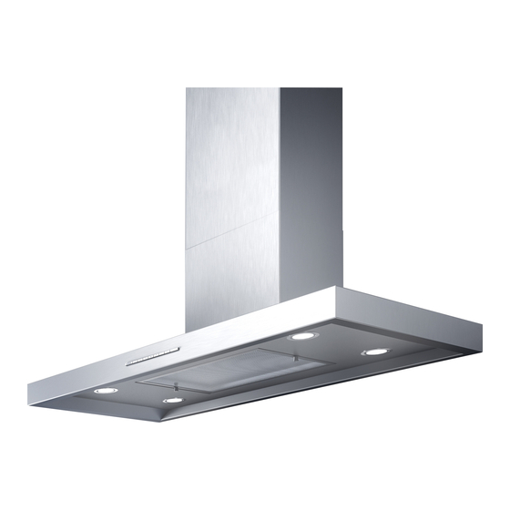
PRODUKTBESCHREIBUNG Varianten / Produktkomponenten Insel Wand 1 Haubenkörper 2 Unterturm A Haubenkörper 3 Oberturm B Unterturm 4 Steuerung innenliegend C Oberturm 5 Elektrischer Anschluss D Elektrisches Anschlußkabel 6 Wandhaltelaschen E Anschlußstutzen 7 Turmhaltelasche F Verschraubungspunkte 8 Anschlußstutzen G Schnellmontageflansch 9 Motormodul H Aufhängepunkte 10 Gummipuffer (rechts / links) -
Seite 9: Masszeichnungen
PRODUKTBESCHREIBUNG Maßzeichnungen Insel-Deckenbefestigung Turmhaltewinkel für Wandbefestigung... - Seite 10 PRODUKTBESCHREIBUNG Maßzeichnungen Campo W 600 / 900 1200 Doppelturm 1500 Abluft Umluft Doppelturm...
- Seite 11 PRODUKTBESCHREIBUNG Maßzeichnungen Palma W 600 / 750 900 / 1000 1200 / 1500 Abluft Umluft...
- Seite 12 PRODUKTBESCHREIBUNG Maßzeichnungen Sombra W 900 / 1200 / 1400 Abluft Umluft...
-
Seite 13: Montageanleitung
MONTAGEANLEITUNG Montagevorbereitung Bauseitige Vorbereitungen Für die Montage der Haube sind bauseitige Voraussetzungen für eine reibungslose Monta- ge der Haube zu schaffen, Küchengeräte abdecken - Hindernisse entfernen. Geeignete Abluftführung in der Decke vorbereiten, Zwischendecke öffnen, Durchbrüche er- stellen etc.. Vor dem Bohren in der Wand, sicherstellen das keine dahinterliegenden Lei- tungen beschädigt werden können. -
Seite 14: Wandmontage
MONTAGEANLEITUNG Wandmontage 1. Positionen für folgende Befestigungslöcher mit Hilfe der angegebenen Abmessungen festlegen. Fehlende Abmessungen sind vom Modell abhängig und müssen an der Hau- be gemessen werden. Auf Mindestabstand zwischen Kochstelle und Unterkante der Dunstabzugshaube achten. 2 Löcher (Ø6mm) für die Aufhängung des Oberturms (Turmhaltelasche). 2 Löcher (Ø10mm) für die Befestigung der Dunstabzugshaube (Haltelaschen). - Seite 15 MONTAGEANLEITUNG Wandmontage 4. Für die Befestigung der Wandhaltela- schen 2 Stockschrauben soweit in die Dübel (Ø10 mm) einschrauben, dass noch ca. 20 mm hervorstehen. 5. Dunstabzugshaube aufhängen und Muttern locker befestigen. 6. Dunstabzugshaube ausrichten (Montagemaße prüfen), Muttern anziehen. 7. Bei Bedarf Dunstabzugshaube (je nach Modell und Haubengröße) mit zwei zusätzlichen Schrauben befestigen.
- Seite 16 MONTAGEANLEITUNG Wandmontage 11. Gummipuffer rechts und links je einmal an das Modul kleben. 12. Halteauskerbungen am Oberturm ca. 2- 3mm nach außen biegen. Folie an den Wandseitigen flächen abziehen. 13. Oberturm in die Haltelasche der Turmauf- hängung einschieben bis dieser einrastet. 14.
-
Seite 17: Decken - Inselmontage
MONTAGEANLEITUNG Decken - Inselmontage 1. (Bei Abluftbetrieb) Geeignete Abluftfüh- rung in der Wand / Decke vorbereiten. 2. Bedienseite der Haube festlegen auf der Seite, auf der sich das Bedienfeld befindet. 3. Um eine optimale Abzugskapazität zu erreichen, Position der Dunstabzugs- haube mittig über der Kochstelle festle- gen (ein Lot zur Hilfe nehmen) und den Mittelpunkt des Turmes an der Decke... - Seite 18 MONTAGEANLEITUNG Deckenmontage - Inselmontage 8. Oberturm über Abluftschlauch elektrische Anschlußkabel schieben, denn Oberturm an den Schlüssellö- chern vom Schnellmontageflansch an den Stockschrauben der Decke einfüh- ren. Turm ausrichten und Muttern anzie- hen. Bei längeren Obertürmen Spezial- werkzeug 1000, Artikl.Nr. 55999800 verwenden. 9.
- Seite 19 MONTAGEANLEITUNG Deckenmontage - Inselmontage 1 = Unterturm 2 = Oberturm 3 = Motormodul 5 = Verschraubungspunkte 6 = Haubenkörper 12.Den Haubenkörper mit Motormodul von unten in den Turm schieben bis die Verschrau- bungspunkte Deckungsgleich sind. Abstandsmaß prüfen Dann die 4 Stück M5 Verbin- dungsschrauben eindrehen, Haube ausrichten, Schrauben fest drehen.
-
Seite 20: Deckenmontage - Inselmontage - Einteiliger Turm
MONTAGEANLEITUNG Deckenmontage - Inselmontage - einteiliger Turm 1. Kunststoff - Blindstopfen am Modul entfer- nen ( 4 Stück ), Blechschrauben am Modul - deckel herausdrehen ( 4 Stück ). 2. 2. Rohr von unten in das Motormodul schieben bis der Metallclip innen am Deckel vom Motormodul anliegt ( 4 x ). - Seite 21 MONTAGEANLEITUNG Deckenmontage - Inselmontage - einteiliger Turm 5. Die Dunstabzugshaube mit Motormodul anheben und die Gewindestangen vom Turm in die Rohre einführen bis der Haubenkörper am Turm anliegt. 6. Die Gewindestangen vom Turm schau- en nun ~15mm am Rohr heraus. Diese mit M8 Muttern verschrauben, dabei darauf achten dass der Turm allseitig am Haubenkörper anliegt.
-
Seite 22: Bauseitiger Fensterkontaktschalter
MONTAGEANLEITUNG Bauseitiger Fensterkontaktschalter ( bei Abluftbetrieb ) Kontakt geschlossen ! Kontakt geöffnet ! Dunstabzugsbetrieb nur bei Betrieb bei geschlossenem Fenster geöffnetem Fenster oder deaktiviert wenn Ansaugung von Zuluft-Kanal möglich Abgas-Emission möglich Bitte beachten Sie, dass ihre Gastherme oder ihr offener Kamin die Abgase durch Konvek- tion erwärmten Abluft... -
Seite 23: Allgemeine Themen
ALLGEMEINE THEMEN Reinigung Nach Abschluss der Montagearbeiten empfehlen wir die Reinigung der Edelstahloberflä- chen mit unserem Spezialreiniger TZ 710. Für die Reinigung der Glasoberflächen empfeh- len wir den Glasreiniger mit der Art.-Nr. 05999704. Für Aluminiumoberflächen verwenden Sie bitte ein weiches Mikrofasertuch, keine trockenen Tücher oder Scheuermittel. Benutzen Sie unbedingt ein mildes Fensterreinigungsmittel und keine aggressiven, säure- oder lau- genhaltigen Reiniger ! Hinweis:... - Seite 24 Dear customer , Thank you for your decision to buy a GUTMAN extractor hood ! Please carefully read the following information and explanations on the proper use of your new GUTMAN hood before using the appliance for the first time. Please also read our operating and installation instructions as well as the cleaning recommendations to ensure that you enjoy many years of service from your appliance.
-
Seite 25: Preliminary Remarks
TABLE OF CONTENTS PAGE PRELIMINARY REMARKS Warnings and symbols : Safety instructions : 27 - 28 Mounting accessories / mounting material / tools : PRODUCT DESCRIPTION Variants : Product components : Dimension drawings : 31 - 34 ASSEMBLY INSTRUCTIONS Assembly preparation : Wall mounting : 36 - 38 Ceiling - island mounting :... -
Seite 26: Preliminary Notes
PRELIMINARY NOTES Warning notice and symbols Warnings in these operating instructions are placed in front of an instruction that may result in personal injury or property damage. Measures to avert a hazard must be observed. WARNING- MEANING SIGNS Warning of a danger spot ! Indicates potentially dangerous situations. -
Seite 27: Safety Instructions
PRELIMINARY NOTES Safety instructions Installation, connection, startup and repairs may be carried out by technicians only. Techni- cians can specify a suitable attachment and exhaust air conduction for the extractor hood. The attachment must be suitable for the weight of the extractor hood and for the load on the wall. - Seite 28 Minimum distance from an Schematic exhaust air routing electric cooking appliance Optimum extraction performance is achie- Operation only with supply air damper or ved when the hood is mounted at a height possible when the window is open. of at least 650 mm from the top edge of the worktop.
- Seite 29 Mounting accessories / mounting material / tools - single tower Wall mounting 2x hanger bolt M8x80 - SW6 - TX25 2x screw 6x45 DIN 571 ( option ) 2x hexagon nut M8 DIN EN 1664 2x washer 6,4 DIN 125 2x expansion dowel S10 (UX10) 2x expansion dowels S8 ( option ) 2x rubber buffer...
-
Seite 30: Product Description
PRODUCT DESCRIPTION Variants / Product components Island Wall 1 Bonnet body A Canopy body 2 Lower tower 3 Upper tower B Lower tower C Upper tower 4 Internal control unit 5 Electrical connection D Electrical connection cable 6 Wall mounting brackets E Connection nozzle 7 Tower retaining bracket F Screw connection points... -
Seite 31: Dimension Drawings
PRODUCT DESCRIPTION Dimension drawings Island ceiling attachment Tower mounting bracket for wall mounting... - Seite 32 PRODUCT DESCRIPTION Dimension drawings Tower support Campo W bracket 600 / 900 1200 Double-Tower exhaust air Power - socket in this area ! ambient air...
- Seite 33 PRODUCT DESCRIPTION Dimension drawings Palma W 600 / 750 900 / 1000 1200 / 1500 exhaust air ambient air...
- Seite 34 PRODUCT DESCRIPTION Dimension drawings Sombra W 900 / 1200 / 1400 exhaust air ambient air...
-
Seite 35: Assembly Preparation
ASSEMBLY INSTRUCTIONS Assembly preparation On-site preparations For the installation of the hood, the customer must ensure that the hood can be installed smoothly, cover kitchen appliances - remove obstacles. Prepare suitable exhaust air ducting in the ceiling, open false ceiling, create openings, etc. Before drilling in the wall, ensure that no pipes behind it can be damaged. -
Seite 36: Wall Mounting
ASSEMBLY INSTRUCTIONS Wall mounting 1. Determine positions for the following mounting holes using the dimensions given. Mis- sing dimensions depend on the model and must be measured on the hood. Ensure that there is a minimum distance between the hob and the lower edge of the cooker hood. - Seite 37 ASSEMBLY INSTRUCTIONS Wall mounting 4. Screw 2 hanger bolts into the wall plugs (Ø10 mm) to fix the wall mounting bra- ckets until they protrude by approx. 20 5. Hang up the cooker hood and loosely fasten the nuts. 6. Align the cooker hood (check mounting dimensions), tighten the nuts.
- Seite 38 ASSEMBLY INSTRUCTIONS Wall mounting 11.Rubber buffer right and left each once to the module. 12.Bend the holding notches on the upper tower approx. 2-3mm to the outside. Pull off the foil on the wall side surfaces. 13.Push the upper tower into the holding tab of the tower suspension until it locks into place.
- Seite 39 ASSEMBLY INSTRUCTIONS Ceiling - island mounting 1. (For exhaust air operation) Prepare suitable exhaust air ducting in the wall / ceiling. 2. Determine the operating side of the hood on the side where the control pa- nel is located 3. To achieve optimum extraction capacity, determine the position of the cooker hood centrally above the hob (use a plumb bob to help) and mark the centre...
- Seite 40 ASSEMBLY INSTRUCTIONS Ceiling - island mounting 8. Push the upper tower over the exhaust air hose and the electrical connection cable, because the upper tower is inse- rted at the keyholes of the quick mounting flange on the hanger bolts of the ceiling.
- Seite 41 ASSEMBLY INSTRUCTIONS Ceiling - island mounting 1 = Lower tower 2 = Upper tower 3 = Motor module 5 = Screw connection points 6 = Bonnet body 12.Push the canopy body with motor module from below into the tower until the screw connection points are congruent.
- Seite 42 ASSEMBLY INSTRUCTIONS Ceiling mounting - island mounting - single piece tower 1. Remove plastic dummy plugs on the mo- dule (4 pcs.), unscrew self-tapping screws on the module cover (4 pcs.). 2. Push the tube from below into the mo- tor module until the metal clip on the inside of the cover of the motor module is in contact ( 4 x ).
- Seite 43 ASSEMBLY INSTRUCTIONS Ceiling mounting - island mounting - single piece tower 5. Lift the cooker hood with the motor mo- dule and insert the threaded rods from the tower into the tubes until the hood body rests against the tower. 6.
-
Seite 44: On-Site Window Contact-Switch
Functional description : The control of your GUTMANN cooker hood is equipped with a window contact circuit. Only window contact switches approved by DIBt (Deutsches Institut für Bautechnik) may be connected potential-free to the contact loop. -
Seite 45: Environmental Information
Please inform yourself about the acceptance at your responsible recycling yard . Environmental information All models manufactured by GUTMANN are identified in accordance with European Directi- ve 2002/96/EC on waste electrical and electronic equipment (WEEE) . This directive spe- cifies the framework for the EU-wide return and disposal of used appliances . Please ask y- our dealer for information about current disposal methods . - Seite 46 être installés. GUTMANN décline toute responsabilité pour les dommages consécutifs au système d'échappement. Introduction qui pourrait être causée par l'extraction de l'air ambiant. Veuillez faire confirmer l'installation correcte dans ces instructions de montage : Nom de l'employé...
- Seite 47 SOMMAIRE PAGE REMARQUES PRÉLIMINAIRES : Avertissements et symboles : Consignes de sécurité : 49 - 50 Accessoires de montage / Outils : INSTRUCTIONS DE MONTAGE : Variantes : composants des produits : Dessins cotés : 53 - 56 INSTRUCTIONS DE MONTAGE : Préparation de l'Assemblée : Montage mural : 58 - 60...
-
Seite 48: Remarques Préliminaires
REMARQUES PRÉLIMINAIRES Avertissements et symboles Ce manuel contient des mises en garde devant des instructions qui peuvent entraîner des blessures corporelles ou des dommages matériels. Les mesures de prévention des dangers doivent être respectées. SIGNAL DE SIGNIFICATION AVERTIS- SEMENT Mise en garde contre un endroit dangereux ! Désigne des situations potentiellement dangereuses. -
Seite 49: Consignes De Sécurité
REMARQUES PRÉLIMINAIRES Consignes de sécurité Seul un personnel qualifié est autorisé à procéder au montage, aux branchements, à la mi- se en service et aux réparations. Ce spécialiste détermine la fixation et la conduite d’évacu- ation adaptées pour la hotte aspirante. Le type de fixation doit tenir compte du poids de la hotte et de la charge du support. - Seite 50 Schéma d'acheminement de l'air Distance minimum à la cuisinière d'échappement Vous obtenez un débit d’air à la buse maxi- Le fonctionnement n'est possible qu'avec mum si vous montez la hotte à une hauteur un volet d'air frais ou avec une fenêtre ou- de 550 mm à...
- Seite 51 ccessoires de montage / matériel de montage / outils - Tour simple Montage mural 2x boulon de suspension M8x80 - SW6 - TX25 2x vis 6x45 DIN 571 (facultatif) 2x écrou hexagonal M8 DIN EN 1664 2x rondelle 6,4 DIN 125 2x cheville à...
-
Seite 52: Description Du Produit
DESCRIPTION DU PRODUIT Variantes / Composantes du produit Île 1 Corps de capot 2 Tour inférieure 3 Tour supérieure A Corps de capot 4 Unité de contrôle interne B Tour inférieure 5 Raccordement électrique C Tour supérieure 6 supports de fixation murale D Câble de connexion électrique 7 Support de fixation de la tour E Buse de raccordement... - Seite 53 DESCRIPTION DU PRODUIT Plans d'encombrement Fixation du plafond des îles Trous pour les vis de blocage Support de tour pour montage mural...
- Seite 54 DESCRIPTION DU PRODUIT Plans d'encombrement Campo W Support de tour pour 600 / 900 montage mural 1200 Tour double 1500 d'échappement Prise en charge dans ce domaine Circulation de l'air Tour double...
- Seite 55 DESCRIPTION DU PRODUIT Plans d'encombrement Palma W 600 / 750 900 / 1000 1200 / 1500 d'échappement Circulation de l'air...
- Seite 56 DESCRIPTION DU PRODUIT Plans d'encombrement Sombra W 900 / 1200 / 1400 d'échappement Circulation de l'air...
- Seite 57 INSTRUCTIONS DE MONTAGE Préparation de l'assemblée Préparations sur place Pour l'installation de la hotte, le client doit s'assurer que la hotte peut être installée sans problème, couvrir appareils cuisine éliminer obstacles. Préparez des conduits d'évacuation d'air appropriés dans le plafond, ouvrez un faux pla- fond, créez des ouvertures, etc.
- Seite 58 INSTRUCTIONS DE MONTAGE Notice de montage de la hotte murale 1. Dans le mur ou le plafond, preparez un trace d’evacuation d’air vicie approprie (pour evacuation de l’air a l’exterieur). A l’aide des dimensions donnees, determinez Templacement des trous de fixation suivants.
- Seite 59 INSTRUCTIONS DE MONTAGE Notice de montage de la hotte murale 4. Vissez les vis sans tete dans les chevil- les (trous de 10 mm) jusqu’ä ce qu’elles ne depassent plus que de 20 mm. 5. Accrochez la hotte, fixezla sans serrer a l’aide de rondel- les intercalaires et d’ecrous.
-
Seite 60: Wandmontage
INSTRUCTIONS DE MONTAGE Wandmontage 11.Collez les tampons en caoutchouc sur le module une fois à droite et à gauche. 12.Repliez vers l’exterieur sur environ 2 mm les cornieres de guidage du conduit superieur. 13.lntroduisez le conduit superieur dans les pattes de fixation de la Suspension de conduit, jusqu’ä... - Seite 61 INSTRUCTIONS DE MONTAGE Notice de montage de la hotte tlot 1. Preparez une evacuation d’air appro- priee dans le plafond (evacuation de l’air a l’exterieur). 2. Determinez le cöte de commande de la hotte ; le bandeau de commande se trouvera sur ce cöte.
- Seite 62 INSTRUCTIONS DE MONTAGE Notice de montage de la hotte Tlot Glisser la tour haute par dessus le fle- xible d’évacuation et le raccordement électrique, la fixer ensuite avec la plaque d’appui et les écrous, resp. avec la bride de montage rapide au plafond. (Outil spécial type TZ 1000, référence 55999800).
- Seite 63 INSTRUCTIONS DE MONTAGE Notice de montage de la hotte Tlot 1 = Tour haute 2 = Tour basse 3 = Module moteur 4 = Tiroir de commande 5 = Trous oblongs pour la fixation de la hotte 6 = Corps de hotte 12.Relever la hotte aspirante et la glisser dans la tour haute, de sorte que les trous ob longs préparés correspondent aux trous de fixation du module.Fixer la hotte aspirante à...
- Seite 64 INSTRUCTIONS DE MONTAGE Montage tour monobloc 1. Retirer les bouchons factices en plas- tique du module (4 pièces), dévisser les vis autotaraudeuses du couvercle du module (4 pièces). 2. Pousser le tube par le bas dans le mo- dule moteur jusqu'à ce que le clip métallique à...
- Seite 65 INSTRUCTIONS DE MONTAGE Montage tour monobloc 5. Soulevez la hotte avec le module moteur et insérez les tiges filetées de la tour dans les tubes jusqu'à ce que le corps de la hotte repose contre la tour. 6. Les tiges filetées de la tour regardent maintenant à...
- Seite 66 Description fonctionnelle : La commande de votre hotte aspirante GUTMANN est équipée d'un circuit de contact de fenêtre. Seuls les contacteurs de fenêtre homologués par le DIBt (Deutsches Institut für Bau- technik) peuvent être raccordés sans potentiel à...
- Seite 67 Indications environnementales Tous les modèles GUTMANN sont identifiés suivant la directive européenne 2002/96/CE sur les appareils électriques et électroniques (Déchets d'équipements électriques et électroniques - DEE). Cette directive fournit un cadre pour une reprise et une valorisation des anciens appareils au niveau européen.
- Seite 68 Va naturalmente notato che i nostri prodotti sono soggetti ad un processo naturale di usura e invecchiamento. Tutti i diritti sono riservati a GUTMANN GmbH, anche nel caso di richieste di diritti di proprietà industriale. Abbiamo tutti i poteri di smaltimento, come il diritto di copiare e trasmettere.
- Seite 69 INDICE PAGINA OSSERVAZIONI PRELIMINARI : Avvertenze e simboli : Istruzioni di sicurezza : 71 - 72 Accessori di montaggio / Utensili : ISTRUZIONI DI MONTAGGIO : Varianti : componenti del prodotto : Disegni quotati : 75 - 78 ISTRUZIONI DI MONTAGGIO : Preparazione del montaggio : Montaggio a parete : 80 - 82...
-
Seite 70: Avvertenze E Simboli
NOTE PRELIMINARI Avvertenze e simboli Il presente manuale riporta avvertenze relative alle procedure operative in cui sussiste il rischio di lesioni personali o danni materiali. Le misure per proteggersi dal pericolo devono essere rispettate. SEGNALE SIGNIFICATO PERICOLO Avviso di pericolo - punto pericoloso ! Indica una possibile situazione di pericolo. -
Seite 71: Per La Vostra Sicurezza
PAESI BASSI Per la vostra sicurezza Il montaggio, l’allacciamento alla rete, la messa in funzione e le riparazioni devono essere effettuate solamente da personale autorizzato, che ha il compito di scegliere il sistema di fissaggio della cappa adeguato e il sistema di scarico dei fumi e dei gas prodotti. Per il fissaggio e necessario considerare il peso della cappa e il carico che puo sopportare la parete. - Seite 72 Distanza minima dal piano cottura Schema del percorso dell'aria di scarico Per un’aspirazione ottimale la cappa deve Funzionamento solo con serranda aria di essere montata a una distanza di 550mm mandata o possibile quando la finestra è dallo spigolo superiore del piano di lavoro. aperta.
- Seite 73 Accessori di montaggio / materiale di montaggio / utensili - Torre singola Montaggio a parete 2x vite prigioniera M8x80 - SW6 - TX25 2x vite 6x45 DIN 571 (opzionale) 2x dado esagonale M8 DIN EN 1664 2x rondella 6,4 DIN 125 2x tassello di espansione S10 (UX10) 2x tasselli ad espansione S8 ( opzionale ) 2x tampone in gomma...
-
Seite 74: Descrizione Del Prodotto
DESCRIZIONE DEL PRODOTTO Varianti / Componenti del prodotto Isola Muro 1 corpo del cofano 1 Corpo a baldacchino 2 Torre inferiore B Torre inferiore 3 Torre superiore C Torre superiore 4 Unità di controllo interno D Cavo di collegamento elettrico 5 Collegamento elettrico E Ugello di collegamento 6 staffe di montaggio a parete... -
Seite 75: Disegni Dimensionali
DESCRIZIONE DEL PRODOTTO Disegni dimensionali Attacco a soffitto a isola Staffa di montaggio a torre per montaggio a parete... - Seite 76 DESCRIZIONE DEL PRODOTTO Disegni dimensionali Campo W 600 / 900 1200 Doppia Torre 1500 Aria di scarico Circolazione dell'aria Doppia Torre...
- Seite 77 DESCRIZIONE DEL PRODOTTO Disegni dimensionali Palma W 600 / 750 900 / 1000 1200 / 1500 Aria di scarico Circolazione dell'aria...
- Seite 78 DESCRIZIONE DEL PRODOTTO Disegni dimensionali Sombra W 900 / 1200 / 1400 Aria di scarico Circolazione dell'aria...
-
Seite 79: Istruzioni Di Montaggio
ISTRUZIONI DI MONTAGGIO Preparazione del montaggio Preparativi in loco Per l'installazione della cappa, il cliente deve assicurarsi che la cappa possa essere in- stallata senza problemi, coprire gli elettrodomestici della cucina - rimuovere gli ostacoli. Preparare adeguate canalizzazioni dell'aria di scarico nel soffitto, aprire il controsoffitto, creare aperture, ecc. -
Seite 80: Montaggio A Parete
ISTRUZIONI DI MONTAGGIO Montaggio a parete 1. 1. (Per funzionamento ad espulsione d’aria) preparare un idoneo scarico nel muro o nel soffitto. Stabilire le posizioni dei seguenti fori di fissaggio con l’aiuto delle dimensioni indicate. Le misure mancanti dipendono dal modello e devono essere misurate sulla cappa as- pirante. - Seite 81 ISTRUZIONI DI MONTAGGIO Montaggio a parete 4. Awitare le viti prigioniere nei tasselli (fori da 10 mm), in modo ehe sporgano ancora di 20 mm. 5. Appendere la cappa aspirante e fissarla con rondelle e dadi, senza stringere. 6. (Per modelli con vetro) abbas- sare il vetro.
- Seite 82 ISTRUZIONI DI MONTAGGIO Montaggio a parete 11.Tampone di gomma a destra e a si- nistra una volta ciascuno al modulo. 12.Piegare ca. 2-3 mm verso l’esterno le scanalature di sostegno. 13.lnserire la torre superiore nella linguetta di sostegno della sospensione della torre, finche non s’innesta.
- Seite 83 ISTRUZIONI DI MONTAGGIO Soffitti - montaggio a isola 1. (Per funzionamento ad espulsione d’a- ria) predisporre un idoneo scarico nel muro o nel soffitto. 2. Stabilire il lato di comando della cappa aspirante; su questo lato si trova il pan- nello comandi.
- Seite 84 ISTRUZIONI DI MONTAGGIO Soffitti - montaggio a isola 8. Far scorrere la colonna superiore sopra il condotto di uscita per aria di scarico e sui cavi di allacciamento elettrico, dopodiché assicurare la colonna supe- riore al soffitto utilizzando rondelle a spalla e dadi, ovvero mediante la flan- gia di montaggio rapido.
- Seite 85 ISTRUZIONI DI MONTAGGIO Soffitti - montaggio a isola 1 = colonna superiore 2 = colonna inferiore 3 = modulo motore 4 = cassetta di comando 5 = fori ovalizzati per il fiss aggio della cappa 6 = struttura principale della cappa 12.Sollevare la cappa aspirante, facendola scorrere nella colonna superiore, in modo tale che i fori ovalizzati pre-applicati sulla colonna coincidano con i fori di fissaggio sul mo-...
- Seite 86 ISTRUZIONI DI MONTAGGIO Montaggio a soffitto - montaggio a isola - torre monoblocco 1. Rimuovere i tappi fittizi in plastica sul mo- dulo (4 pz.), svitare le viti autofilettanti sul coperchio del modulo (4 pz.). 2. Spingere il tubo dal basso nel modulo motore fino a quando la clip metallica all'interno del coperchio del modulo motore non è...
- Seite 87 ISTRUZIONI DI MONTAGGIO Montaggio a soffitto - montaggio a isola - torre monoblocco 5. Sollevare la cappa con il modulo mo- tore e inserire le aste filettate della torre nei tubi fino a quando il corpo della cappa non si appoggia alla torre. 6.
- Seite 88 Descrizione del funzionamento : Il comando della cappa GUTMANN è dotato di un circuito di contatto finestra. Solo gli interruttori di contatto per finestre approvati dal DIBt (Deutsches Institut für Bautechnik) possono essere collegati a potenziale zero all'anello di contatto.
-
Seite 89: Smaltimento
Nota ambientale Tutti i modelli di produzione GUTMANN sono contrassegnati in base alla Direttiva europea 2002/96/CE sulle apparecchiature elettriche ed elettroniche (waste electrical and electronic equipment – WEEE), la quale sancisce i criteri base per il ritiro e il ricupero di apparecchia- ture usate, validi su tutto il territorio UE. - Seite 90 GUTMANN GmbH se reserva todos los derechos, también en el caso de solicitudes de derechos de propiedad industrial. Tenemos todo el poder de disposición, como el derecho a copiar y transmitir.
-
Seite 91: Observaciones Preliminares
ÍNDICE PÁGINA OBSERVACIONES PRELIMINARES : Advertencias y símbolos : Instrucciones de seguridad : 93 - 94 Accesorios de montaje / Herramientas : INSTRUCCIONES DE MONTAJE : Varianti : componenti del prodotto : Disegni quotati : 97 - 100 INSTRUCCIONES DE MONTAJE : Preparazione del montaggio : Montaggio a parete : 102 - 104... -
Seite 92: Advertencias Y Símbolos
NOTAS PRELIMINARES Advertencias y símbolos En estas instrucciones hay indicaciones de advertencia antes de las instrucciones operativas con las que exista riesgo de daños personales o materiales. Hay que cumplir las medidas para evitar riesgos. SEÑALES SIGNIFICADO DE ADVER- TENCIA Advertencia de un punto peligroso ! Marca posibles situaciones peligrosas. -
Seite 93: Indicaciones De Seguridad
NOTAS PRELIMINARES Indicaciones de seguridad El montaje, la conexiön, la puesta en funcionamiento y las reparaciones, solo pueden ser llevados a cabo por un profesional especializado del ramo, que podrä determinar la fijaciön y la conducciön del aire adecuadas de la campana extractora de humos. La fijaciön tiene que adecuarse al peso de la campana extractora, asi como a la capacidad de carga de la base de sustentaciön (pared o techo en su caso.) Tenga en cuenta los valores de resisten- cia a la extracciön de los tacos que se suministran. - Seite 94 NOTAS PRELIMINARES Distancia mínima a la zona de cocción Esquema de la ruta del aire de escape Funcionamiento sólo con compuerta de Distancia respecto a placas de cocciòn o aire de suministro o posible cuando la cocinas electricas La distancia mfnima ent- ventana está...
- Seite 95 Accesorios de montaje / material de montaje / herramientas - Torre única Montaje en la pared 2x pernos de suspensión M8x80 - SW6 - TX25 2x tornillo 6x45 DIN 571 (opcional) 2x tuerca hexagonal M8 DIN EN 1664 2x arandela 6,4 DIN 125 2x clavija de expansión S10 (UX10) 2x clavijas de expansión S8 ( opcional ) 2x parachoques de goma...
-
Seite 96: Descripción Del Producto
DESCRIPCIÓN DEL PRODUCTO Variantes / Componentes del producto Isla Muro 1 cuerpo del sombrero 2 Torre baja A Cuerpo del sombrero 3 Torre superior B Torre baja 4 Unidad de control interno C Torre superior 5 Conexión eléctrica D Cable de conexión eléctrica 6 soportes de montaje en la pared E Boquilla de conexión 7 Soporte de retención de la torre... -
Seite 97: Dibujos Dimensionales
DESCRIPCIÓN DEL PRODUCTO Dibujos dimensionales Fijación del techo de la isla Soporte de montaje de la torre para el montaje en la pared... - Seite 98 DESCRIPCIÓN DEL PRODUCTO Dibujos dimensionales Campo W 600 / 900 1200 Torre doble 1500 El aire de escape Circulación de aire Torre doble...
- Seite 99 DESCRIPCIÓN DEL PRODUCTO Dibujos dimensionales Palma W 600 / 750 900 / 1000 1200 / 1500 El aire de escape Circulación de aire...
- Seite 100 DESCRIPCIÓN DEL PRODUCTO Dibujos dimensionales Sombra W 900 / 1200 / 1400 El aire de escape Circulación de aire...
-
Seite 101: Preparación Del Montaje
INSTRUCCIONES DE MONTAJE Preparación del montaje Preparativos in situ Para la instalación de la campana, el cliente debe asegurarse de que la campana se pue- de instalar sin problemas, cubrir los electrodomésticos de la cocina - eliminar los obstácu- los. Preparar conductos de aire de escape adecuados en el techo, abrir el falso techo, crear aberturas, etc. -
Seite 102: Montaje En La Pared
INSTRUCCIONES DE MONTAJE Montaje en la pared 1. (Para los aparatos con evacuaciòn del aire al exterior): Prepare la conducciòn del aire en la pared o en el techo. Determine las posiciones para los agujeros de fijaciòn. Para ello, tenga en cuenta las distancias mfnimas entre la zona de cocciòn y el borde inferior de la campana extrac- tora. - Seite 103 INSTRUCCIONES DE MONTAJE Montaje en la pared 4. Enrosque los tornillos de sujeciön de la campana en los tacos (en los agujeros de 10 mm), dejando unos 20 mm de rosca libre. 5. Enganche el cuerpo de la campa- na en los tornillos de sujeciön. Coloque las arandelas y tuercas correspondientes, apretändolas...
- Seite 104 INSTRUCCIONES DE MONTAJE Montaje en la pared 11.Pegue los amortiguadores de goma al módulo una vez a la derecha y a la izquierda. 12.Torcer hacia fuera aprox. 2-3mm las muescas de soporte en el tubo superi- or. Modo inverso aldescrito para abati- rla.
- Seite 105 INSTRUCCIONES DE MONTAJE Montaje campana isla funcionamiento de extractor 1. (En caso de funcionamiento de extrac- tor) Preparar un conducto de aire de salida apropiado en la pared / el techo. Determinar el lado de control de la campana en el lado que se encuentra el panel de control.
- Seite 106 INSTRUCCIONES DE MONTAJE Montaje campana isla funcionamiento de extractor 8. Desplace la torreta superior sobre el tubo de evacuación y el cable de conexión eléctrica y fíjela al techo con arandelas y tuercas o con la brida de montaje rápido.(herramienta especial tipo TZ 1000, nº...
- Seite 107 INSTRUCCIONES DE MONTAJE Montaje campana isla funcionamiento de extractor 1 = Torreta superior 2 = Torreta inferior 3 = Módulo de motor 4 = Cajón de control 5 = Ranuras para fijación de campana 6 = Cuerpo de la campana 12.Levante la campana e introdúzcala en la torreta superior, de modo que las ranuras coincidan con los orificios de fijación del módulo.
- Seite 108 INSTRUCCIONES DE MONTAJE Techos - montaje en isla - torre de una sola pieza 1. Retire los tapones de plástico del módulo (4 piezas), desatornille los tornillos autor- roscantes de la tapa del módulo (4 piezas). 2. Empujar el tubo desde abajo dentro del módulo del motor hasta que la abraza- dera metálica en el interior de la cubierta del módulo del motor esté...
- Seite 109 INSTRUCCIONES DE MONTAJE Techos - montaje en isla - torre de una sola pieza 5. Levante la campana de la cocina con el módulo del motor e inserte las varillas roscadas de la torre en los tubos hasta que el cuerpo de la campana descanse contra la torre.
-
Seite 110: Instrucción De Montaje
Descripción funcional : El mando de su campana extractora GUTMANN está equipado con un circuito de contacto de ventana. Sólo los interruptores de contacto de ventana autorizados por el DIBt (Instituto Alemán de Técnica ) pueden conectarse sin potencial al bucle de contacto. -
Seite 111: Indicaciones Medioambientales
TEMAS GENERALES Limpieza Después de terminar el montaje recomendamos limpiar las superficies de acero inoxidable con nuestro limpiador especial TZ 710. Para la limpieza de las superficies de vidrio recomendamos el limpiacristales Art. Para superficies de aluminio, utilice un paño suave de microfibra. - Seite 112 Er moet natuurlijk worden opgemerkt dat onze producten onderhevig zijn aan een natuurlijk slijtage- en verouderingsproces. Alle rechten zijn voorbehouden aan GUTMANN GmbH, ook bij aanvragen voor industriële eigendomsrechten. Wij hebben alle beschikkingsbevoegdheid, zoals het recht om te kopiëren en door te geven.
-
Seite 113: Inleidende Opmerkingen
INHOUD PAGINA INLEIDENDE OPMERKINGEN : Waarschuwingen en symbolen : Veiligheidsinstructies : 115 - 116 Bevestigingsmateriaal / Gereedschap : MONTAGE-INSTRUCTIES : Varianten : Productcomponenten : Maattekening: 119 - 122 MONTAGE-INSTRUCTIES : Montagevoorbereiding : Wandmontage : 124 - 126 Plafond - eilandmontage : 127 - 129 Plafondmontage - eilandmontage - toren uit één stuk : 130 - 131... -
Seite 114: Waarschuwingen En Symbolen
VOORLOPIGE OPMERKINGEN Waarschuwingen en symbolen In deze handleiding staan waarschuwingen voor instructies waarbij gevaar voor persoonlijk letsel of schade aan voorwerpen bestaat. Houd u aan de maatregelen om het gevaar te voorkomen. WAAR- STEKEN BETEKENIS SCHUW- Waarschuwing voor een gevaarlijke plek ! Geeft een mogelijk gevaarlijke situatie aan. - Seite 115 VOORLOPIGE OPMERKINGEN Veiligheidsvoorschriften, Gevaar Montage, aansluiting, ingebruikNeming en reparatie mögen alleen worden uitgevoerd door een vakman. Deze kan de geschikte bevestiging en luchtafvoerwijze van de af-zuigkap be- palen.De bevestiging moet geschikt zijn voor het gewicht van de afzuigkap en de belasting van de ondergrond.
- Seite 116 Minimumafstand tot fornuis Schematische afvoerluchtroutering De minimumafstand tussen de onderkant Betrieb nur mit Zuluft-Klappe oder van de afzuigkap en de kookzones of kook- bei geöffnetem Fenster möglich. platen bedraagt 550 mm. De minimumaf- stand tussen de onderkant van de afzuig- kap en de kookzones of kookplaten be- draagt 650 mm.
- Seite 117 Montagezubehör / Montagematerial / Werkzeug - Einzelturm Wandmontage 2x stokbout M8x80 - SW6 - TX25 2x schroef 6x45 DIN 571 (optioneel) 2x zeskantmoer M8 DIN EN 1664 2x wasmachine 6,4 DIN 125 2x uitbreidingsdeuvel S10 (UX10) 2x expansiedeuvels S8 ( optioneel ) 2x rubberbuffer Plafondmontage 4x stokbout M8x80 - SW6 - TX25...
-
Seite 118: Productbeschrijving
PRODUCTBESCHRIJVING Varianten / Productcomponenten Eiland Muur 1 Motorkap lichaam A Hemellichaam 2 Onderste toren B Onderste toren 3 Bovenste toren C Bovenste toren 4 Interne controle-eenheid D Elektrische aansluitkabel 5 Elektrische aansluiting E Aansluitmondstuk 6 Muurbeugels F Schroefaansluitpunten 7 Torenbeugel G Snelle montageflens 8 Aansluitmondstuk H Schorsingspunten... - Seite 119 PRODUCTBESCHRIJVING Maatschetsen Eilandplafondbevestiging Torenmontagebeugel voor wandmontage...
- Seite 120 PRODUCTBESCHRIJVING Maatschetsen Campo W 600 / 900 1200 Doppelturm 1500 Uitlaatlucht Luchtcirculatie Dubbele Toren...
- Seite 121 PRODUCTBESCHRIJVING Maatschetsen Palma W 600 / 750 900 / 1000 1200 / 1500 Uitlaatlucht Luchtcirculatie...
- Seite 122 PRODUCTBESCHRIJVING Maatschetsen Sombra W 900 / 1200 / 1400 Uitlaatlucht Luchtcirculatie...
- Seite 123 INSTALLATIEHANDLEIDING Montagevoorbereiding Voorbereidingen ter plaatse Voor de installatie van de afzuigkap moet de klant ervoor zorgen dat de afzuigkap prob- leemloos kan worden geïnstalleerd, keukenapparatuur afdekken - obstakels verwijderen. Bereid geschikte luchtafvoerkanalen voor in het plafond, open een verlaagd plafond, maak openingen, enz.
-
Seite 124: Wandmontage
INSTALLATIEHANDLEIDING Wandmontage 1. (Bij gebruik met afvoerlucht) Bereid een geschikte luchtafvoeropening in de muur of het plafond voor. Bepaal de posities van de volgende bevestigingsgaten met behulp van deaangegeven maten. Ontbrekende maten zijn afhankelijk van het model en moe- ten op de kap worden gemeten. Let daarbij op de minimumafstand tussen de kook- plaat en de onderkant van de afzuigkap. - Seite 125 INSTALLATIEHANDLEIDING Wandmontage 4. Schroef de schroeven zo ver in de plug- gen (10 mm gaten) dat de schroeven nog 20 mm uitsteken. 5. Hang de afzuigkap op en bevestig deze losjes met onderlegringen en moeren. 6. (bij modeilen met een glas- plaat) Klap de glasplaat om- laag.
- Seite 126 INSTALLATIEHANDLEIDING Wandmontage 11.Lijm de rubberen buffers eenmaal rechts en links op de module. 12.Buig de bevestigingskerven in de boventoren ca. 2 mm naar buiten. 13.iS.Schuif de boventoren in de bevesti- gingslip van de torenophanging tot hij goed vastzit. 14.Buig de ondertoren iets open en plaats hem over de boventoren en de afzuig- kap.
- Seite 127 INSTALLATIEHANDLEIDING Plafondmontage - Eilandmontage 1. (Bij gebruik met afvoerlucht) Bereid een geschikte luchtafvoeropening in het plafond voor. 2. Bepaal de bedieningszijde van de kap; aan deze zijde bevindt zieh het bedie- ningspaneel. 3. Om een optimale afzuigcapaciteit te bereiken moet de positie van de afzuig- kap midden boven het fornuis worden vastgelegd (gebruik een schietlood);...
- Seite 128 INSTALLATIEHANDLEIDING Plafondmontage - Eilandmontage 8. De boventoren over de slang voor de afgevoerde lucht + de elektrische aansluitingskabel schuiven, en daarna de boventoren met onderlegplaatjes en moeren resp. met de snelmontageflens aan het plafond bevestigen. (speciaal gereedschap type TZ 1000, artikel-nr. 55999800) 9.
- Seite 129 INSTALLATIEHANDLEIDING Plafondmontage - Eilandmontage 1 = boventoren 2 = ondertoren 3 = motormodule 4 = lade voor sturing 5 = langsgaten voor kapbevestiging 6 = kaplichaam 12.De dampkap opheffen en in de boventoren schuiven zodat de vooraf aangebrachte langsgaten met de bevestigingsgaten op de module overeenstemmen.De dampkamp aan de boventoren bevestigen (de meegeleverde M5 schroeven gebruiken).
- Seite 130 INSTALLATIEHANDLEIDING Plafondmontage - eilandmontage - toren uit één stuk 1. Kunststof – De blinde stop op de mo- dule verwijderen stuks) plaatschroef op de module uitdraaien (4 stuks) 2. Metalen clips in de buis schuiven en in de moer insluiten, eventueel met een hamer (4 stuks) 3.
- Seite 131 INSTALLATIEHANDLEIDING Plafondmontage - eilandmontage - toren uit één stuk 5. Nu de tapstangen in de buis steken. De kap kan nu met de tapstangen gemon- teerd worden. 6. De draadstangen van de toren kijken nu ~ 15 mm uit de buis. Draai deze vast met M8 moeren en zorg ervoor dat de toren aan alle kanten contact maakt met de kap.
- Seite 132 Functionele beschrijving : De bediening van uw GUTMANN dampkap is uitgerust met een raamcontactcircuit. Alleen door DIBt (Deutsches Institut für Bautechnik) goedgekeurde raamcontact- schakelaars...
- Seite 133 Informeer u a.u.b. over de acceptatie bij uw verantwoordelijke recyclingbedrijf". Milieu-instructies Alle modellen van de firma GUTMANN zijn volgens de Europese richtlijn over elektrische en elektronische toestellen (waste electrical and electronic equipment – WEEE) geken- merkt. De richtlijn beschrijft het kader voor een EU-wijde geldige terugname en recyclage van oude toestellen.
- Seite 134 Las etiquetas energéticas y las hojas de datos de productos pueden consultarse en Internet en www.gutmann-exklusiv.eu Queda pro- hibida la reproducción, modificación, utilización o difusión de la información aquí publicada sin la autorización escrita de Exklusiv-Hauben...
- Seite 135 à la technologie d'impression. Les étiquettes énergétiques et les fiches techniques des produits peuvent être consultées sur Internet à l'adresse www.gutmann- exklusiv.eu La reproduction, la modification, l'utilisation ou la diffusion des informations publiées ici sont interdites sans l'autorisati- on écrite de Exklusiv-Hauben GUTMANN GmbH.
- Seite 136 Energy label data and product datasheets can be viewed on our website at www.gutmann-exklusiv.eu. The reproduction, modifi- cation, utilisation and/or dissemination of the information published herein without prior, written authorisation having been provid-...