Herunterladen Inhalt Inhalt Diese Seite drucken
GUTMANN Sombra Montageanleitung
Vorschau ausblenden Andere Handbücher für Sombra:

Werbung

Verfügbare Sprachen

Verfügbare Sprachen

de
Montageanleitung
fr
Notice de montage
it
Istruzioni per il montaggio
en
Installation Instructions
Solo
Siento

Werbung

Inhaltsverzeichnis
loading

Inhaltszusammenfassung für GUTMANN Sombra

  • Seite 1 Montageanleitung Notice de montage Istruzioni per il montaggio Installation Instructions Solo Siento...
  • Seite 2: Sicherheitshinweise

    keine elektrische Leitungen durch das Boh- ren beschädigt werden können. Der Elektro- Sicherheitshinweise anschluss muss so vorbereitet werden, dass die Dunstabzugshaube damit einfach ange- Montage, Anschluss, Inbetriebnahme und schlossen werden kann. Örtliche Bestimmun- Reparatur dürfen nur von einer Fachkraft gen müssen eingehalten werden. durchgeführt werden.
  • Seite 3 Gas-Herde Vor der Montage Ihrer Wandhaube ist der Mittelpunkt der Kernlochbohrung für den Ab- Belastung einer Kochstelle max. 3,0 kW luftschlauch durch die Wand (außer Umluft- Belastung aller Kochstellen max. 8,3 kW hauben), sowie die Dübellöcher für den Belastung des Backofens max.
  • Seite 4 Elektroanschluß so, daß später ein leichter sen können (nach dem Bohren Bohr- Anschluß der Haube möglich ist. Achten Sie schablone entfernen). Bohren Sie bitte die bitte darauf, daß der Abluftschlauch so we- drei Befestigungslöcher mit einem Loch- nig wie zur weiteren Montage nötig, aus dem durchmesser von 6mm.
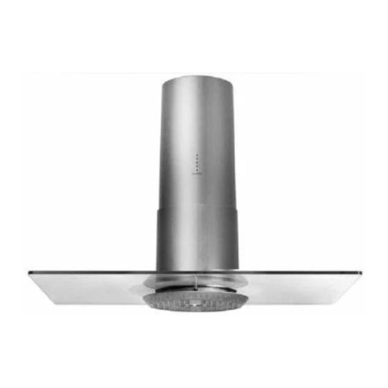
  • Seite 5 sen provisorisch mit Klebedand Legen Sie nun die Glasplatte an das Hauben- modul an, führen Sie den Glashalter durch Montageanleitung Inselhaube Bild: mit Aktivkohlefilter (a) Vor der Montage Ihrer Inselhaube legen Sie bitte die Position über dem Kochfeld fest. Den das Loch in der Scheibe ein und schrauben Mittelpunkt des Turmes (Abluftführung durch Sie diesen mit Hilfe der vorab gelösten...
  • Seite 6 tigt an der Sie die Lochposition genau able- sen können (nach dem Bohren die Loch- schablone und angefallene Späne entfernen). Schrauben Sie nun bitte die Stockschrauben in die Dübel und lassen Sie diese ca. 20mm herausschauen. Befestigen Sie die Unterleg- scheiben und Muttern an den Stock- schrauben.
  • Seite 7 Entfernen Sie das provisorisch angebrachte Klebeband und lassen Sie den Unterturm lansam auf die Haube herab. Der Abluftschlauch muss stets knickfrei ver- legt werden. Vor elektrischen Arbeiten an der Dunstabzugshaube unbedingt den Netzste- cker ziehen. Entsorgung Lampe und Steuerung durch die Stecker- kupplung, sowie die Verbindung zwischen Verpackung Schalter und Steuerung.
  • Seite 9: Consignes De Sécurité

    Conduit d‘évacuation (pour le mode aspirant) Consignes de sécurité L’évacuation ne doit pas être conduite vers une cheminée qui est utilisée pour l’évacuation de gaz émis par des appareils à Seul un personnel qualifié est autorisé à combustion (p. ex le gaz).Respectez les procéder au montage, aux branchements, à...
  • Seite 10: Instruction De Montage

    Cuisinieres ä gaz se) ainsi que les trous de chevilles pour la bride de fixation murale. La distance entre le Charge thermique d’un foyer 3,0 kW maxi. bord superieur de la tour et le centre du Charge therm.de tous les foyers 8,3 kW maxi. carottage au diamant s’eleve ä...
  • Seite 11 hauteur totale de la hotte entre 680 et 830mm raccorder la hotte. Poussez le module de / 800 et 950 mm). La tour superieure est hotte, dans la tour superieure et 1 avec les munie d’un calibre sur lequel vous pouvez boulons (AAS) par les trous de fixation perces relever exactement la position du trou auparavant.
  • Seite 12 ainsi que le raccordement entre la fiche et la commande. Fichez le cäble ä basse ter des Instruction de montage diodes lumineuses de la tour superieure dans la commande. Solo/Siento hotte insulaire Maintenant montez le filtre de graisse en le tournant en: inverse des aiguilles d’une Avant le montage de votre hotte insulaire fixez montre.
  • Seite 13 regard de la hotte que si peu que necessaire les ecrous, mais laissez une distance au pour le montage ulterieur. plafond d’environ 6mm. Aontez maintenant la tour superieure en l’enfongant sur les ecrous boulonnes et l’arretez par torsion. Maintenant serrez les ecrous fortement et arretez la tour contre torsion en serrant une autre vis par le trou de 10mm dans la tour Maintenant portez votre hotte sur mesure...
  • Seite 14: Elimination Des Déchets

    Poussez la piece de decoration sur la tour Ja fixation murale et accrochez-le.Executez montee et attachez-la ä l’aide du materiel de un contröle de fonctionnement. Le tuyau fixation fourni.Posez la plaque de verre contre d’echappement doit toujours etre pose sans le module de hotte, introduisez le porte-verre coudes.
  • Seite 16: Per La Vostra Sicurezza

    creare i buchi di fissaggio, accertarsi che nessuna linea elettrica possa essere Per la vostra sicurezza danneggiata durante l’operazione. L’allacciamento alla rete elettrica deve Il montaggio, l’allacciamento alla rete, la consentire un facile collegamento della messa in funzione e le riparazioni devono cappa di aspirazione.
  • Seite 17: Istruzioni Per Il Montaggio

    Cucine a gas Carico termico di un for- max. 3,0 kW nello Carico termico tutti i for- max. 8,3 kW nelli Carico termico del fomo max. 3.9 kW Piani di cottura a gas Carico termico di un for- max. 3,9 kW nello Carico termico tutti i for- max.
  • Seite 18 allora la torretta sarä montata owiamente a all’unitä di controllo sia la lampada sia raso; in questo caso la distanza del centro l’interruttore. Per Ultimo svitare le viti del foro di scarico e la parete deve essere di 240 mm. fermavetro, il quäle va tolto girandolo in senso Perforare i buchi, inserire i tasselli e fissare antiorario.
  • Seite 19: Istruzioni Peril

    controllo e collegare pure a quesfultima il II canale di rivestimento deve essere infilato cavetto a basso voltaggio dei diodi luminosi sulla flangia di fissaggio alla parete e proveniente dalla torretta superiore. agganciato. Effettuare il controllo funzionale! II tubo flessibile di scarico dell’aria dev’essere sempre sistemato senza pieghe! Prima di qualsiasi lavoro alle parti elettriche della cappa staccare assolutamente la presa...
  • Seite 20 tasselli per il fissaggio al soffitto. fori (una volta forati questi Ultimi, togliere sia Predisporre i fori (010 mm) per il montaggio la sagoma, sia eventuali trucioli). della torretta superiore e infilare i relativ! Awitare le astine (le viti ad asta per i fori a tasselli.
  • Seite 21 esagono cavo (M5) nei fori apposit1 messi Effettuare il controllo funzionale! precedentemente a punto. II tubo flessibile di scarico dell’aria dev’essere Infilare ora il cofano decorativo sulla torretta sempre sistemato senza pieghe! montata e bloccarlo con i pezzi fissatori forniti. Prima di qualsiasi lavoro alle parti elettriche A questo punto montare la lastra di vetro sul della cappa staccare assolutamente la presa...
  • Seite 22: Safety Instructions

    be prepared in such a manner that the Safety Instructions exhaust hood can be easily connected to it. Local conditions must be complied with. Installation, connection, startup and repairs may only be conducted by a service Exhaust Air Flow (Exhaust Operation) technician.
  • Seite 23: Installation Instructions

    Gas Cooktops (with the exception of recirculation hoods) as well as the screw anchor holes for the wall Load of one cooking area max. 3.9 kW attachment flange should be drawn using the Load of all cooking areas max. 11.3 kW installation stencil provided.
  • Seite 24 allow the low voltage wiring to the light diodes to protrude from the upper tower for later connection. The electrical connection to the (with the exception of recirculation hoods) and the electrical connection in such a manner that connecting the hood will be simple later on.
  • Seite 25 please insert the low voltage wiring for the light diodes in the upper tower into the controls. First hang the safety chain between the glass holder and grease filter. Then please install the grease filter by turning it clockwise (recirculating hoods are provided with an ad- ditional active carbon filter).
  • Seite 26 and please allow the low voltage wiring to the hoods) and the electrical connection in such light diodes to protrude from the upper tower a manner that connecting the hood will be simple later on. Please ensure that only as for later connection.
  • Seite 27: Environmental Instructions

    it with the help of the previously loosened screws (shift lever must be pointing forward) Disposal tightly to the hood module. Create the connection between the lamps and controls Packaging by the connector coupling, as well as the The packaging of the exhaust hood is connection between the switch and controls.
  • Seite 28 Ø 10 Image: Solo Island Ceiling Installation Image: Solo Wall Installation...
  • Seite 32 Exklusiv-Hauben Mühlackerstraße 77 D-75417 Mühlacker Tel. (49) 0 70 41/8 82-0 Fax (49) 0 70 41/4 68 82 Internet: http://www.gutmann-exklusiv.de E-Mail: info@gutmann-exklusiv.de HRB 705602 Amtsgericht Mannheim DE263391836 Index: 11/09 Artikel Nr.: 67201340...

Diese Anleitung auch für:

Solo

Inhaltsverzeichnis