Herunterladen Inhalt Inhalt Diese Seite drucken
Inhaltsverzeichnis

Werbung

Verfügbare Sprachen
  • DE

Verfügbare Sprachen

  • DEUTSCH, seite 1
Illuminosa
Gaskochfeld
Gas cooking top
Table de cuisson à gaz
Cocina a gas
Fornello a gas
10035464 10035465

Werbung

Inhaltsverzeichnis
loading

Inhaltszusammenfassung für Klarstein Illuminosa

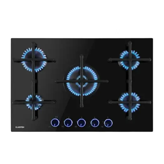
  • Seite 1 Illuminosa Gaskochfeld Gas cooking top Table de cuisson à gaz Cocina a gas Fornello a gas 10035464 10035465...
  • Seite 3: Inhaltsverzeichnis

    Sehr geehrter Kunde, wir gratulieren Ihnen zum Erwerb Ihres Gerätes. Lesen Sie die folgenden Hinweise sorgfältig durch und befolgen Sie diese, um möglichen Schäden vorzubeugen. Für Schäden, die durch Missachtung der Hinweise und unsachgemäßen Gebrauch entstehen, übernehmen wir keine Haftung. Scannen Sie den folgenden QR-Code, um Zugriff auf die aktuellste Bedienungsanleitung und weitere Informationen rund um das Produkt zu erhalten.
  • Seite 4: Technische Daten

    TECHNISCHE DATEN Artikelnummer 10035464 Brenner Gastyp Druck Injektor­ Wärmeeintrag durchmesser Bezeichnung mbar 1/100 mm G30 (Butan) 28-30 Wokbrenner G30 (Butan) G20 (Erdgas) Starkbrenner (R) – – – – G30 (Butan) 28-30 1,75 Normalbrenner (SR) G30 (Butan) 1,75 G20 (Erdgas) 1,75 G30 (Butan) 28-30 Hilfsbrenner (AUX)
  • Seite 5: Sicherheitshinweise

    SICHERHEITSHINWEISE Lesen Sie sich die Bedienungsanleitung vor der Installation und Verwendung des Geräts aufmerksam durch. Bewahren Sie die Bedienungsanleitung für den zukünftigen Gebrauch auf. Sollten Sie das Gerät an eine andere Person weitergeben, achten Sie darauf, dass die Bedienungsanleitung ebenfalls an den neuen Besitzer weitergegeben wird.
  • Seite 6 • Die das Gerät umgebenden Materialien und Möbel müssen einer Mindesttemperatur standhalten können, die 85 °C über der Raumtemperatur des Raumes liegt, in dem sich das Gerät befindet. • Sollte die Flamme des Gasherdes versehentlich ausgehen, schalten Sie die Brennerregelung aus. Der Brenner darf innerhalb der nächsten Minute nicht eingeschaltet werden.
  • Seite 7 • Verwenden Sie hitzeresistente Topflappen oder Handschuhe, wenn Sie mit heißen Töpfen oder Pfannen hantieren. • Achten Sie darauf, dass Topflappen oder Handschuhe nicht feucht oder nass werden, da dies dazu führen kann, dass das Material die Hitze schneller leitet, was zu Verbrennungen führen kann.
  • Seite 8: Geräteübersicht

    • Schalten Sie das Gerät, im Fall einer Störung oder eines Defekts sofort aus und ziehen Sie den Netzstecker aus der Steckdose. Versuchen Sie niemals, das Gerät selbst zu reparieren. Wenden Sie sich an den Kundendienst oder an in ähnlicher Weise qualifiziertes Fachpersonal.
  • Seite 9 Artikelnummer 10035465 Wokbrenner Hilfsbrenner (AUX) Starkbrenner (R) Bedienregler Gasbrenner Normalbrenner (SR) Pfannenhalter für Gasbrenner Hinweis: Die Größe der Pfannenhalter entspricht jeweils der Größe der Gasbrenner. Achten Sie darauf, dass Sie die Pfannenhalter immer am Brenner mit dem passenden Durchmesser installieren.
  • Seite 10: Installation (Installateur)

    INSTALLATION (INSTALLATEUR) Technische Informationen • Die Installation sowie die Einstellungen, Umbauten und Wartungen des Geräts dürfen nur von einem qualifizierten Techniker oder Installateur durchgeführt werden. Der Hersteller kann nicht für Personen- oder Sachschäden haftbar gemacht werden, die auf eine fehlerhafte Installation des Geräts zurückzuführen sind. •...
  • Seite 11 Standort und Belüftung Gasgeräte müssen die Verbrennungsprodukte immer über an Rauchfänge angeschlossene Abzüge oder direkt nach außen abführen (siehe Abbildung 2). Wenn es nicht möglich ist, einen Abzug zu benutzen, ist ein am Fenster oder an einer nach außen gerichteten Wand installierter Ventilator zulässig, der bei jeder Benutzung des Geräts eingeschaltet werden muss (siehe Abbildung 3), sofern die geltenden Vorschriften und Bestimmungen für die Belüftung eingehalten werden.
  • Seite 12 Installation und Befestigung des Kochfelds Die Abmessungen des Hohlraums im oberen Teil des modularen Schranks, in den das Kochfeld eingelassen wird, sind in Abbildung 4 angegeben. Halten Sie einen Mindestabstand von 750 mm von Schränken oder Hauben zur Oberseite des Geräts ein.
  • Seite 13 Artikelnummer 10035465 Abbildung 4 Wichtiger Hinweis: Es ist notwendig, unter dem Kochfeld immer eine Trennwand aus Holz anzubringen, die mindestens 70 mm vom Boden desselben entfernt und leicht abnehmbar sein muss, um eventuelle Wartungsarbeiten zu ermöglichen (siehe Abbildung 5). Abbildung 5...
  • Seite 14 Kochfeld abdichten Das Kochfeld verfügt über eine spezielle Dichtung, die das Eindringen von Flüssigkeit in das Gehäuse verhindert. Um diese Dichtung korrekt anzubringen, müssen die folgenden Anweisungen streng eingehalten werden: • Kleben Sie die Rückseite der umgekehrten Seitenkante mit dem Schaumgummipolster ab (siehe Abbildung 6).
  • Seite 15: Gasanschluss Installieren (Installateur)

    GASANSCHLUSS INSTALLIEREN (INSTALLATEUR) Hinweis: Die Installation sowie Einstellung, Umbauten und Wartungsarbeiten am Gerät dürfen nur von einem qualifizierten Techniker oder Installateur vorgenommen werden. Schließen Sie das Gerät nicht selbst an die Gasversorgung an! Wichtige Hinweise zum Gasanschluss • Bevor Sie das Gerät an das Gasnetz anschließen, überprüfen Sie, ob die Angaben auf dem Typenschild, das sich auf der Unterseite des Geräts befindet, mit den Angaben auf dem entsprechenden im Gasnetz vorhandenen Typenschild übereinstimmen.
  • Seite 16: Gerät Einstellen (Installateur)

    In jedem Fall sollte die Leitung, die das Gerät mit der Gasversorgung verbindet, mit glatten Biegungen verlegt werden. Die Gummidichtung, die vom Installateur zwischen dem Gaseinlassanschluss des Geräts und dem Leitungsanschluss angebracht wird, muss der Norm EN 549 entsprechen (erhältlich im Fachhandel). VORSICHT Gefahr von Sach- und Personenschäden! Beim Anschluss des Geräts an die Gasversorgung muss jede Art der Belastung des Geräts...
  • Seite 17: Umbau Des Geräts (Installateur)

    • Bei Hähnen mit Sicherheitsthermoelementen befindet sich die Einstellschraube an der Seite des Stutzens. • Stellen Sie sicher, dass beim schnellen Drehen von der Maximalen Position (große Flamme) in die Minimale Position (kleine Flamme) der Brenner nicht erlischt. Hinweis: Wenn der Hahn nach langem Gebrauch des Kochfeldes bei der Drehung eine gewisse Reibung aufweist, wenden Sie sich an den Kundendienst, damit der Hahn ersetzt wird.
  • Seite 18: Wartung (Installateur)

    WARTUNG (INSTALLATEUR) Hinweis: Trennen Sie das Gerät vor allen Wartungsarbeiten und vor dem Austausch von Teilen von der Gas- und Stromversorgung. Komponenten austauschen • Um an das Schaltpult und das Netzkabel zu gelangen, muss das Kochfeld durch Lösen der entsprechenden Befestigungsschrauben (V) aus dem Gehäuse entfernt werden (siehe Abbildung 7).
  • Seite 19 Gasbrenner • Die Brenner sind in ihrer Größe und Leistung so abgestuft, dass sie genau die Hitze liefern, die für jede Art des Kochens erforderlich ist. • Die Brenner können mit einer Flammensicherung (FSD = Thermoelement, siehe Abbildung 9) ausgestattet werden. •...
  • Seite 20 Automatische elektrische Zündung (nur bei bestimmter Geräteausstattung, siehe Abbildung 9, Bezeichnung Ac) 1. Die Steuerung der Zündung ist im Drehknopf integriert. Drücken und drehen Sie den Drehknopf, der dem gewünschten Brenner entspricht, von der Position „OFF“ (Aus) im Uhrzeigersinn bis zur Maximalen Position (große Flamme, siehe Abbildung 10). Der Zündfunke wird automatisch gezündet.
  • Seite 21: Reinigung Und Pflege

    Abbildung 11 Topf­/Pfannen­Durchmesser (Ø in cm) Artikelnummer Starkbrenner Normalbrenner Hilfsbrenner 10035464 24-26 – 20-22 10-15 10035465 24-26 24-26 20-24 10-15 REINIGUNG UND PFLEGE Hinweis: Schalten Sie vor der Reinigung und Wartung das Gerät immer aus und ziehen Sie den Netzstecker aus der Steckdose. Kochfeldoberfl äche reinigen •...
  • Seite 22: Fehlersuche Und Fehlerbehebung

    Befolgen Sie die nachstehenden Anweisungen, bevor Sie die Komponenten wieder einsetzen: • Überprüfen Sie, ob die Brennerköpfe und die entsprechenden Brennerdeckel korrekt in ihren Gehäusen positioniert sind (siehe Abbildung 9). • Stellen Sie sicher, dass die Brennerkopfschlitze nicht durch Fremdkörper blockiert werden.
  • Seite 23: Produktdatenblatt

    PRODUKTDATENBLATT Symbol Brenner Wert Einheit Modellkennung 10035464 Art der Kochmulde Gaskochmulde Anzahl der Gasbrenner – – – Wokbrenner 52,2 Starkbrenner – Energieeffizienz je EE gas Gasbrenner burner Normalbrenner 2 x 58,1 Hilfsbrenner Energieeffizienz der EE gas hob 56,1 Gasmulde Symbol Brenner Wert Einheit...
  • Seite 25 Dear Customer, Congratulations on purchasing this device. Please read the following instructions carefully and follow them to prevent possible damages. We assume no liability for damage caused by disregard of the instructions and improper use. Scan the QR code to get access to the latest user manual and more product information.
  • Seite 26: Technical Data

    TECHNICAL DATA Item number 10035464 Burners Gas types Pressures Injectors Heat Inputs diameter Denomination mbar 1/100 mm G30 (Butane) 28-30 G30 (Butan) G20 (Natural) Rapid (R) – – – – G30 (Butane) 28-30 1.75 Semi-Rapid (SR) G30 (Butan) 1.75 G20 (Natural) 1.75 G30 (Butane) 28-30...
  • Seite 27: Safety Instructions

    SAFETY INSTRUCTIONS Please take the time to read this instruction manual before installing or using the appliance. This instruction booklet must be kept with the appliance for any future reference. If the appliance is sold or transferred to another person,ensure the booklet is passed on to the new user.
  • Seite 28 • Prolonged intensive use of the appliance may call for additional ventilation, for example opening of a window, or more effective ventilation, for example increasing he level of mechanical ventilation where present. • Keep children near the appliance under supervision. Do not allow children to play near or with the appliance.
  • Seite 29 • Always turn burner controls off before removing cookware. • Carefully watch foods being fried at a high flame setting. • Always heat fat slowly and watch as it heats. • Foods for frying should be as dry as possible. Frost on frozen foods or moisture on fresh foods can cause hot fat to bubble up and over the sides of the pan.
  • Seite 30: Device Overview

    DEVICE OVERVIEW Item number 10035464 Wok gas burner Gas burner control knob Semi­Rapid gas burner (SR) Pan support for burners Auxiliary gas burner (Aux) Note: Pan supports are the same in shape. Pay attention to put them in proper position, according to the burners’ diameter!
  • Seite 31 Item number 10035465 Wok gas burner Auxiliary gas burner (Aux) Rapid gas burner (R) Gas burner control knob Semi­Rapid gas burner (SR) Pan support for burners Note: Pan supports are the same in shape. Pay attention to put them in proper position, according to the burners’...
  • Seite 32: Installation (Installer)

    INSTALLATION (INSTALLER) Technical information • The installation, the adjustments, conversions and maintenance of the appliance must only be carried out by a qualified technician or installer. The manufacturer cannot be held responsible for any damage to persons or things deriving from an incorrect installation of the appliance.
  • Seite 33 Location and aeration Gas appliances must always discharge the products of combustion through extractors connected to fl ues or directly to the outside (see fi gure 2). If it is impossible to use an extractor, a fan installed on the window or on a wall facing the outside is allowed and should be switched on each time the appliance is used (see fi gure 3), provided the rules and regulations in force relating to ventilation.
  • Seite 34 Installing and fixing the hob The measurements of the cavity made in the top of the modular cabinet and into which the hob will be recessed are indicated in figure 4. Cupboards or hoods have to maintain a least distance of 750 mm from the top. Item number 10035464 Figure 4...
  • Seite 35 Item number 10035465 Figure 4 Important note: Under the hob it is necessary to always apply a panel of separation in wood, positioned to a least distance of 70 mm by the bottom of the same, which has to easily be removable to allow possible operations of maintenance (see figure 5).
  • Seite 36 Sealing the hob The hob has a special seal which prevents liquid from infiltrating into the cabinet. Strictly comply with the following instructions in order to correctly apply this seal: • Back board of the reverse side’ edge use the foam-rubber cushion to paste a round (see figure 6).
  • Seite 37: Gas Connection (Installer)

    GAS CONNECTION (INSTALLER) Note: The installation, the adjustments, conversions and maintenance of the appliance must only be carried out by a qualifi ed technician or installer. Do not connect the appliance to the gas supply yourself! Important notes on gas connection •...
  • Seite 38: Adjusting The Appliance (Installer)

    ADJUSTING THE APPLIANCE (INSTALLER) • Check the adjustment of the appliance, before to make any adjusting operation, having a look on proper adjustment sticker data plate, put on the bottom of the appliance. • Before any adjustment is attempted, which may be necessary when installing for the first time or when converting gas type, take the plug out of the mains socket.
  • Seite 39: Conversion Of The Appliance (Installer)

    CONVERSION OF THE APPLIANCE (INSTALLER) Changing the injectors • The burners can be adapted to different types of gas by simply installing the injectors suitable for the gas you want to use. The “kit injectors” can be supplied together with the appliance or purchased. •...
  • Seite 40: Operation

    OPERATION Important notes on operation • When the burners or plates are in use do not leave them unattended and make sure there are no small children in the vicinity. Check that pan handles are positioned correctly and always keep an eye on the pan whenever oils or fats are used as they are easily inflammable.
  • Seite 41 Off position Maximum position (big flame) Minimum position (little flame) Ignite Figure 10 Automatic electrical ignition (only certain versions, see figure 9, ref. Ac) 1. The command of lighting is integrated in the control knob. Press and turn anclockwise the knob corresponding to the burner you wish to use from “Off” position, until it reaches the “Maximum”...
  • Seite 42: Cleaning And Care

    • When the contents of the pan start boiling, turn the knob down to the “Minimum” position with reduced rate (small fl ame). • Always put a lid on the pan. Figure 11 Pan diameter (Ø in cm) Item number Rapid Semi­Rapid Auxiliary...
  • Seite 43: Troubleshooting

    Comply with the following instructions, before remounting the parts: • Check that the heads burners and the relative burner caps are correctly positioned in their housings (see figure 9). • Check that burner head slots have not become clogged by foreign bodies. •...
  • Seite 44: Product Data Sheet

    PRODUCT DATA SHEET Symbol Burner Value Unit Model identification 10035464 Type of hob Gas Hob Number of gas burner – – – Wok burner 52.2 Rapid burner – Energy efficiency per EE gas burner gas burner Semi-rapid burner 2 x 58.1 Auxiliary burner Energy efficiency per EE gas hob...
  • Seite 45 Chère cliente, cher client, Toutes nos félicitations pour l’acquisition de ce nouvel appareil. Veuillez lire attentivement et respecter les instructions de ce mode d’emploi afin d’éviter d’éventuels dommages. Nous ne saurions être tenus pour responsables des dommages dus au non-respect des consignes et à...
  • Seite 46: Fiche Technique

    FICHE TECHNIQUE Numéro d'article 10035464 Brûleurs Type de gaz Pression Diamètre des Apport injecteurs calorifique N° Description mbar 1/100 mm G30 (butane) 28-30 Brûleur wok G30 (butane) G20 (gaz naturel) Brûleur puissant – – – – G30 (butane) 28-30 1,75 Brûleur normal G30 (butane) 1,75...
  • Seite 47: Consignes De Sécurité

    CONSIGNES DE SÉCURITÉ Lisez attentivement le mode d‘emploi avant d‘installer et d‘utiliser l‘appareil. Conservez le mode d‘emploi pour vous y référer ultérieurement. Si vous transmettez l‘appareil à une autre personne, assurez-vous de transmettre également le mode d‘emploi au nouveau propriétaire. •...
  • Seite 48 • Les matériaux et les meubles entourant l‘appareil doivent pouvoir résister à une température minimale de 85 °C au-dessus de la température ambiante de la pièce dans laquelle se trouve l‘appareil. • Si la flamme de la cuisinière à gaz s‘éteint accidentellement, éteignez la commande du brûleur.
  • Seite 49 • Utilisez des maniques ou des gants résistants à la chaleur pour manipuler des casseroles ou des poêles chaudes. • Assurez-vous que les maniques ou les gants ne sont pas humides ou mouillés, car cela peut provoquer une conductivité thermique plus rapide du matériau et entraîner des brûlures.
  • Seite 50: Aperçu Des Appareils

    • En cas de panne ou de défaut, éteignez immédiatement l‘appareil et débranchez la fiche secteur de la prise. N‘essayez jamais de réparer l‘appareil vous-même. Contactez le service client ou un personnel qualifié. Ayez à disposition toutes les informations de l‘appareil sur la plaque signalétique. •...
  • Seite 51 Numéro d‘article 10035465 Brûleur wok Brûleur auxiliaire (AUX) Brûleur fort (R) Régulateur brûleur à gaz Brûleur normal (SR) Support de casserole pour brûleurs à gaz Remarque : La taille du support de casserole correspond à la taille du brûleur à gaz. Veillez à...
  • Seite 52: Installation (Installateur)

    INSTALLATION (INSTALLATEUR) Informations techniques • L‘installation ainsi que les réglages, modifications et maintenance de l‘appareil ne peuvent être effectués que par un technicien ou installateur qualifié. Le fabricant ne peut être tenu responsable des blessures ou dommages matériels résultant d‘une mauvaise installation de l‘appareil.
  • Seite 53 Emplacement et ventilation Les appareils à gaz doivent toujours évacuer les produits de la combustion par des conduits de fumée raccordés à une cheminée ou directement à l‘extérieur (voir fi gure 2). S‘il n‘est pas possible d‘utiliser un extracteur, un ventilateur installé près de la fenêtre ou sur un mur extérieur est autorisé...
  • Seite 54 Installation et fixation de la table de cuisson Les dimensions de l‘ouverture dans la partie supérieure de l‘armoire modulaire dans laquelle la plaque de cuisson sera encastrée sont données sur la figure 4. Maintenez une distance minimale de 750 mm entre les armoires ou les hottes et le haut de l‘appareil.
  • Seite 55 Numéro d‘article 10035465 Figure 4 Remarque importante : il est toujours nécessaire d‘installer une cloison en bois sous la plaque de cuisson, à au moins 70 mm du fond de la plaque et facilement amovible pour permettre d‘effectuer les éventuels travaux d‘entretien (voir figure 5). Figure 5...
  • Seite 56 Étanchéité de la plaque de cuisson La table de cuisson dispose d‘un joint spécial qui empêche les liquides de pénétrer dans le boîtier. Afin d‘appliquer correctement ce joint, les instructions suivantes doivent être strictement suivies : • Collez l‘arrière du bord latéral inversé avec le tampon en caoutchouc mousse (voir Figure 6).
  • Seite 57: Installation Du Branchement Au Gaz (Installateur)

    INSTALLATION DU BRANCHEMENT AU GAZ (INSTALLATEUR) Note : L‘installation, le réglage, la modification et l‘entretien de l‘appareil doivent être effectués par un technicien ou un installateur qualifié. Ne raccordez pas vous- même l‘appareil à l‘alimentation en gaz ! Notes importantes sur le raccordement au gaz •...
  • Seite 58: Réglage De L'appareil (Installateur)

    Dans tous les cas, le fl exible reliant l‘appareil à l‘alimentation en gaz doit être posé avec des coudes aussi plats que possible. Le joint en caoutchouc fi xé par l‘installateur entre le raccord d‘entrée de gaz de l‘appareil et le raccord de tuyau doit être conforme à...
  • Seite 59: Modification De L'appareil (Installateur)

    • Pour les robinets avec thermocouples de sécurité, la vis de réglage se trouve sur le côté de la douille. • Assurez-vous que le brûleur ne s‘éteint pas en tournant rapidement de la position maximale (grande flamme) à la position minimale (petite flamme). Remarque : Si, après avoir utilisé...
  • Seite 60: Maintenance (Installateur)

    MAINTENANCE (INSTALLATEUR) Remarque : Avant tout travail de maintenance et avant de remplacer des pièces, débranchez l‘appareil de l‘alimentation en gaz et en électricité. Remplacer les pièces • Pour accéder au panneau de commande et au câble d‘alimentation, la plaque de cuisson doit être retirée du boîtier en desserrant les vis de fixation correspondantes (V) (voir Figure 7).
  • Seite 61: Allumage Manuel

    Brûleurs à gaz • Les brûleurs sont gradués en taille et en puissance pour fournir exactement la chaleur requise pour tout type de cuisson. • Les brûleurs peuvent être équipés d‘un pare-flammes (FSD = thermocouple, voir Figure 9). • Sur le dessus de chaque bouton, un schéma indique à...
  • Seite 62 Allumage électrique automatique (uniquement avec certains équipements de l‘appareil, voir Figure 9, désignation Ac) 1. La commande d‘allumage est intégrée dans le bouton rotatif. Appuyez sur le bouton correspondant au brûleur souhaité et tournez de la position „OFF“ à la position maximale (grande flamme, voir Figure 10) dans le sens des aiguilles d‘une montre.
  • Seite 63: Nettoyage Et Entretien

    Figure 11 Diamètres des poêles / casseroles (Ø en cm) Numéro Brûleur fort Brûleur normal Brûleur d'article auxiliaire 10035464 24-26 – 20-22 10-15 10035465 24-26 24-26 20-24 10-15 NETTOYAGE ET ENTRETIEN Remarque : Avant de nettoyer et d‘entretenir l‘appareil, éteignez-le toujours et débranchez la fi che de la prise.
  • Seite 64: Identification Et Résolution Des Problèmes

    Suivez les instructions ci-dessous avant de réinstaller les composants : • Vérifiez que les têtes et les chapeaux de brûleur correspondants sont correctement positionnés dans leurs logements (voir Figure 9). • Assurez-vous que les fentes de la tête de brûleur ne sont pas bloquées par des objets étrangers.
  • Seite 65: Fiche De Données Produit

    FICHE DE DONNÉES PRODUIT Symbole Brûleur Valeur Unité Identification du 10035464 modèle Type de plaque Plaque de cuisson au gaz Nombre de brûleurs – – – à gaz Brûleur wok 52,2 Brûleur puissant – Efficacité énergétique EE brûleur à par brûleur à gaz Brûleur normal 2 x 58,1 Brûleur auxiliaire...
  • Seite 67 Estimado cliente, Le felicitamos por la adquisición de este producto. Lea atentamente las siguientes instrucciones y sígalas para evitar posibles daños. No asumimos ninguna responsabilidad por los daños causados por el incumplimiento de las instrucciones y el uso inadecuado. Escanee el siguiente código QR para obtener acceso a la última guía del usuario y más información sobre el producto.
  • Seite 68: Datos Técnicos

    DATOS TÉCNICOS Número de artículo 10035464 Quemador Tipo de gas Presión Diámetro del Entrada inyector de calor N° Denominación mbar 1/100 mm G30 (Butano) 28-30 Quemador wok G30 (Butano) G20 (gas natural) Quemador potente – – – – G30 (Butano) 28-30 1,75 Quemador normal...
  • Seite 69: Indicaciones De Seguridad

    INDICACIONES DE SEGURIDAD Lea atentamente este manual de instrucciones antes del uso e instalación del aparato. Conserve el manual de instrucciones para usos posteriores. Si cede el aparato a otra persona, asegúrese de entregar también el manual de instrucciones al nuevo propietario.
  • Seite 70 • Los materiales y muebles que rodean al aparato deben poder soportar una temperatura mínima que se sitúe 85 °C por encima de la temperatura ambiente de la estancia en la que se encuentra el aparato. • Si la llama de la cocina de gas se apaga accidentalmente, apague el regulador del quemador.
  • Seite 71 • Utilice agarradores o guantes resistentes al calor cuando sujete las ollas o sartenes calientes. • Asegúrese de que los agarradores o guantes no estén mojados ni húmedos, pues esto puede provocar que el material conduzca el calor rápidamente y le genere quemaduras.
  • Seite 72: Vista General Del Aparato

    • Apague el aparato inmediatamente en caso de una avería o defecto y desconecte el enchufe de la toma de corriente. No intente reparar el aparato por su cuenta. Contacte con el servicio de atención al cliente o con una persona igualmente cualificada.
  • Seite 73 Número de artículo 10035465 Quemador wok Quemador auxiliar (AUX) Quemador potente (R) Regulador de control de los quemadores de gas Quemador normal (SR) Soporte de sartén para los quemadores de gas Nota: el tamaño del soporte de sartén corresponde al tamaño del quemador de gas.
  • Seite 74: Instalación (Instalador)

    INSTALACIÓN (INSTALADOR) Información técnica • La instalación y los ajustes, modificaciones y mantenimiento del aparato deben ser realizadas por un técnico o instalador cualificado. El fabricante no se hará responsable de daños materiales o personales provocados por una instalación incorrecta del aparato. •...
  • Seite 75 Ubicación y ventilación Los aparatos de gas siempre deben evacuar los productos de la combustión a través de tubos de escape conectados a una chimenea o directamente al exterior (véase la fi gura 2). Si no es posible utilizar un extractor, se permite la instalación de un ventilador cerca de la ventana o en una pared exterior, que debe encenderse cada vez que se utilice el aparato (véase la fi gura 3), con sujeción a las normas y reglamentos de ventilación aplicables.
  • Seite 76 Instalación y fijación de la placa de cocción Las dimensiones de la abertura en la parte superior del armario modular en el que se empotrará la placa de cocción se indican en la figura 4. Mantenga una distancia mínima de 750 mm entre los armarios o campanas y la parte superior del aparato. Número de artículo 10035464 Ilustración 4...
  • Seite 77 Número de artículo 10035465 Ilustración 4 Información importante: es necesario instalar un separador de madera debajo de la placa de cocción que se sitúe al menos a 70 mm de la base de esta y se pueda extraer fácilmente para facilitar posibles trabajos de mantenimiento (véase ilustración Ilustración 5...
  • Seite 78 Instalación y fijación de la cocina La placa de cocción dispone de una junta especial que evita que se filtren líquidos a la estructura. Para instalar correctamente la junta, debe cumplir estrictamente las siguientes instrucciones: • Despegue la parte trasera del canto lateral que posee el acolchado de gomaespuma (véase ilustración 6).
  • Seite 79: Instalar La Conexión De Gas (Instalador)

    INSTALAR LA CONEXIÓN DE GAS (INSTALADOR) Nota: La instalación, el ajuste, la modificación y el mantenimiento de la unidad deben ser realizados por un técnico o instalador cualificado. ¡No conectes el aparato al suministro de gas tú mismo! Notas importantes sobre la conexión de gas •...
  • Seite 80: Ajustar El Aparato (Instalador)

    En cualquier caso, la manguera que conecta el aparato al suministro de gas debe colocarse con los codos más planos posibles. La junta de goma colocada por el instalador entre la conexión de entrada de gas del aparato y la conexión de la manguera debe cumplir la norma EN 549 (disponible en los comercios especializados).
  • Seite 81: Transformación Del Aparato (Instalador)

    • En las llaves con elementos térmicos de seguridad, el tornillo de ajuste se sitúa a los lados de los soportes. • Asegúrese de que al pasar rápidamente desde la posición máxima (llama grande) a la posición mínima (llama pequeña) el quemador no se apague. Nota: Si, después de usar la placa de cocción durante un período prolongado, la llave se roza al girar, póngase en contacto con el servicio de atención al cliente para que le cambien la llave.
  • Seite 82: Mantenimiento (Instalador)

    MANTENIMIENTO (INSTALADOR) Nota: antes de realizar los trabajos de mantenimiento y de sustituir piezas, desconecte el suministro eléctrico y de gas. Sustituir los componentes • Para acceder a la placa de terminales y al cable de alimentación, es necesario desmontar la placa de cocción soltando los tornillos de fijación correspondientes (V) de la carcasa (consultar ilustración 7).
  • Seite 83 Quemadores de gas • Los quemadores están graduados en tamaño y potencia para proporcionar exactamente el calor necesario para cualquier tipo de cocina. • Los quemadores pueden estar equipados con un pararrayos de llama (FSD = termopar, ver Figura 9). •...
  • Seite 84 Encendido eléctrico automático (sólo con ciertos equipos en el aparato, véase la figura 9, designación Ac) 1. El control de encendido está integrado en el mando giratorio. Presione la perilla correspondiente al quemador deseado y gire desde la posición “OFF“ hasta la posición máxima (llama grande, ver Figura 10) en el sentido de las agujas del reloj.
  • Seite 85: Limpieza Y Cuidado

    Ilustración 11 Diámetro de olla/sartén (Ø en cm) Número de Quemador Quemador Quemador artículo potente normal auxiliar 10035464 24-26 – 20-22 10-15 10035465 24-26 24-26 20-24 10-15 LIMPIEZA Y CUIDADO Nota: Apague el aparato y desconecte el enchufe de la toma de corriente antes de limpiarlo y de realizar mantenimiento.
  • Seite 86: Detección Y Resolución De Problemas

    Siga estas instrucciones antes de volver a colocar los componentes: • Compruebe que los cabezales de los quemadores y sus correspondientes tapas estén correctamente colocados en sus carcasas (consultar ilustración 9). • Asegúrese de que las ranuras del quemador no se obstruyan con objetos extraños. •...
  • Seite 87: Hoja De Datos Del Producto

    HOJA DE DATOS DEL PRODUCTO Símbolo Quemador Valor Unidad Identificación del 10035464 modelo Tipo de placa de Placa de gas cocina Número de – – – quemadores de gas Quemador wok 52,2 Eficiencia energética Quemador potente – EE quemador por quemador de de gas Quemador normal 2 x 58,1...
  • Seite 89 Gentile cliente, La ringraziamo per aver acquistato il dispositivo. La preghiamo di leggere attentamente le seguenti istruzioni per l’uso e di seguirle per evitare possibili danni. Non ci assumiamo alcuna responsabilità per danni scaturiti da una mancata osservazione delle avvertenze di sicurezza e da un uso improprio del dispositivo.
  • Seite 90: Dati Tecnici

    DATI TECNICI Numero articolo 10035464 Bruciatore Tipo di gas Pressione Diametro Immissione iniettore calore N° Denominazione mbar 1/100 mm G30 (Butano) 28-30 Bruciatore wok G30 (Butano) G20 (gas naturale) Bruciatore rapido – – – – G30 (Butano) 28-30 1,75 Bruciatore semi- G30 (Butano) 1,75 rapido (SR)
  • Seite 91: Avvertenze Di Sicurezza

    AVVERTENZE DI SICUREZZA Leggere attentamente il manuale d’uso prima di installare e utilizzare il dispositivo. Conservare il manuale per futuri utilizzi. Se il dispositivo viene dato a un’altra persona, accludere il manuale d’uso. • Il dispositivo deve essere installato in un locale ben ventilato e nel rispetto delle norme applicabili.
  • Seite 92 • Materiali e mobili intorno al dispositivo devono poter tollerare una temperatura minima superiore di 85 °C rispetto alla temperatura ambiente della stanza in cui si trova il dispositivo. • Se la fiamma del dispositivo viene spenta involontariamente, spegnere il bruciatore e non riaccenderlo per qualche minuto.
  • Seite 93 • Utilizzare presine termoresistenti quando si maneggiano pentole e padelle bollenti. • Assicurarsi che le presine non diventino umide o bagnate, altrimenti il calore viene trasmesso più velocemente dal materiale correndo il rischio di ustionarsi. • Accendere il bruciatore solo dopo averci posizionato sopra la pentola o la padella.
  • Seite 94: Panoramica Del Dispositivo

    • In caso di difetti o malfunzionamenti, spegnere immediatamente il dispositivo e togliere la spina dalla presa. Non provare mai a riparare il dispositivo autonomamente. Rivolgersi al servizio di assistenza o a un tecnico specializzato e tenere a disposizione tutti i dati sulla targhetta del dispositivo. •...
  • Seite 95 Numero articolo 10035465 Bruciatore wok Bruciatore ausiliario (AUX) Bruciatore rapido (R) Manopola per bruciatore Bruciatore semi­rapido Reggi pentola per bruciatore (SR) Nota: le dimensioni del reggi pentola corrispondono alle dimensioni del bruciatore. Assicurarsi di installare sempre i reggi pentola sul bruciatore con il diametro adatto.
  • Seite 96: Installazione (Installatore)

    INSTALLAZIONE (INSTALLATORE) Note tecniche • Le installazioni, regolazioni, modifiche e manutenzioni del dispositivo devono essere eseguite solo da tecnici qualificati o installatori. Il produttore non può essere ritenuto responsabile per danni a persone o cose riconducibili a un’installazione errata del dispositivo. •...
  • Seite 97 Posizione e ventilazione Gli apparecchi a gas devono sempre scaricare i prodotti della combustione attraverso i tubi di scarico collegati ad un camino o direttamente all‘esterno (vedi fi gura 2). Se non è possibile utilizzare un ventilatore di scarico, è consentito installare un ventilatore vicino alla fi nestra o su una parete esterna, che deve essere acceso ogni volta che si utilizza l‘apparecchio (vedi fi gura 3), nel rispetto delle norme e dei regolamenti applicabili in materia di ventilazione.
  • Seite 98 Installazione e fissaggio della piastra di cottura Le dimensioni dell‘apertura nella parte superiore dell‘armadio modulare in cui deve essere inserito il piano cottura sono indicate nella figura 4. Mantenere una distanza minima di 750 mm tra gli armadi o le cappe e la parte superiore dell‘apparecchio. Numero articolo 10035464 Figura 4...
  • Seite 99 Numero articolo 10035465 Figura 4 Avvertenza importante: sotto il piano di cottura deve essere installato una parete divisoria di legno che si trovi ad almeno 70 mm dalla base del piano di cottura e che possa essere facilmente rimosso per facilitare eventuali lavori di manutenzione (vedi illustrazione 5).
  • Seite 100 Installazione e fissaggio della cucina Il piano cottura è dotato di una speciale guarnizione che impedisce la fuoriuscita di liquidi nella struttura. Per una corretta installazione della guarnizione è necessario attenersi scrupolosamente alle seguenti istruzioni: • Rimuovere il lato posteriore del bordo laterale con l‘imbottitura in schiuma (vedi illustrazione 6).
  • Seite 101: Collegare L'allacciamento Del Gas (Installatore)

    COLLEGARE L’ ALLACCIAMENTO DEL GAS (INSTALLATORE) Nota: L‘installazione, la regolazione, la modifica e la manutenzione dell‘apparecchio devono essere eseguite da un tecnico o da un installatore qualificato. Non collegare l‘apparecchio alla rete del gas da soli! Avvertenze importanti per l‘allacciamento del gas •...
  • Seite 102: Regolazione Del Dispositivo (Installatore)

    In ogni caso la conduttura che collega il dispositivo alla rete del gas deve essere posata con pieghe piatte. La guarnizione di gomma, che viene applicata tra il collegamento d’ingresso del gas del dispositivo e il collegamento della conduttura, deve essere conforme alla norma EN 549 (reperibile dal rivenditore specializzato).
  • Seite 103: Modifica Del Dispositivo (Installatore)

    • Nei rubinetti corredati di termocoppie di sicurezza la vite di regolazione si trova di lato del rubinetto. • Mentre si gira la manopola velocemente dalla posizione massima (fiamma grande) a quella minima (fiamma piccola), assicurarsi che la fiamma non si spenga. Nota: Se, dopo aver utilizzato il piano cottura per un lungo periodo, la chiave si sfrega durante la rotazione, contattare il servizio clienti per far sostituire la chiave.
  • Seite 104: Manutenzione (Installatore)

    MANUTENZIONE (INSTALLATORE) Nota: prima di eseguire lavori di manutenzione e sostituzione di parti, spegnere l‘alimentazione elettrica e il gas. Sostituzione dei componenti • Per arrivare al quadro dei comandi e al cavo d’alimentazione, bisogna rimuovere il piano cottura dall’alloggiamento svitando le relative viti di fissaggio (V) (vedi figura 7).
  • Seite 105 Bruciatori a gas • I bruciatori sono graduati nelle dimensioni e nella potenza per fornire esattamente il calore necessario per qualsiasi tipo di cottura. • I bruciatori possono essere dotati di un dispositivo di arresto della fiamma (FSD = termocoppia, vedi figura 9).
  • Seite 106 Accensione elettrica automatica (solo con determinate apparecchiature sul dispositivo, vedi figura 9, designazione Ac) 1. Il controllo di accensione è integrato nel comando rotativo. Spingere la manopola corrispondente al bruciatore desiderato e ruotare dalla posizione “OFF“ alla posizione massima (fiamma grande, vedi figura 10) in senso orario. La scintilla si accenderà...
  • Seite 107: Pulizia E Manutenzione

    Figura 11 Diametro pentola/padella (ø in cm) Codice articolo Bruciatore Bruciatore Bruciatore rapido semi­rapido ausiliario 10035464 24-26 – 20-22 10-15 10035465 24-26 24-26 20-24 10-15 PULIZIA E MANUTENZIONE Nota: staccare la spina dalla presa e spegnere sempre il dispositivo prima di pulirlo o eseguire lavori di manutenzione.
  • Seite 108: Ricerca E Correzione Degli Errori

    Seguire le indicazioni seguenti prima di reinserire le componenti: • Verificare che le teste dei bruciatori e i relativi coperchi siano posizionati correttamente negli alloggiamenti (vedi figura 9). • Assicurarsi che le fessure delle teste dei bruciatori non siano bloccate da corpi estranei.
  • Seite 109: Scheda Informativa Del Prodotto

    SCHEDA INFORMATIVA DEL PRODOTTO Simbolo Bruciatore Valore Unità Identificativo del 10035464 modello Tipologia di piano Piano cottura a gas cottura Numero di – – – bruciatori a gas Bruciatore wok 52,2 Efficienza Bruciatore rapido – energetica per EE gas burner ciascun bruciatore Bruciatore semi-rapido 2 x 58,1...

Diese Anleitung auch für:

1003546410035465

Inhaltsverzeichnis