Herunterladen Inhalt Inhalt Diese Seite drucken
Inhaltsverzeichnis

Werbung

Verfügbare Sprachen
  • DE

Verfügbare Sprachen

  • DEUTSCH, seite 1
SB356
3 609 929 B67/
2008-11

Werbung

Inhaltsverzeichnis
loading

Inhaltszusammenfassung für Bosch Rexroth SB356

  • Seite 1 SB356 3 609 929 B67/ 2008-11...
  • Seite 2 2/124 2/124 Bosch Rexroth AG Bosch Rexroth AG SB356 | 3 609 929 B67/2008-11 SB356 | 3 609 929 B67/2008-11 Deutsch ......3 English .
  • Seite 3: Inhaltsverzeichnis

    Alterungsprozess unterliegen. Instandhaltung und Instandsetzung ..19  Alle Rechte bei Bosch Rexroth AG, auch Außerbetriebnahme ....19 für den Fall von Schutzrechtsanmeldungen.
  • Seite 4: Zu Dieser Anleitung

    4/124 Bosch Rexroth AG SB356 | 3 609 929 B67/2008-11 Zu dieser Anleitung • Geben Sie die Systembox SB356 an Dritte stets zusammen mit der Diese Anleitung enthält wichtige Bedienungsanleitung weiter. Informationen, um die Systembox SB356 sicher und sachgerecht zu montieren, zu Bestimmungsgemäße Verwendung...
  • Seite 5: Qualifikation Des Personals

    3 609 929 B67/2008-11 | SB356 Bosch Rexroth AG 5/124 Qualifikation des Personals Dieses Warnsymbol warnt Sie vor Die Montage, Inbetriebnahme und Gefahren für Ihre Gesundheit. Be- Bedienung, Demontage, Instandhaltung (inkl. folgen Sie alle Sicherheitshin- Wartung und Pflege) erfordern weise, die diesem Symbol folgen, grundlegende elektrische und mechanische um mögliche Verletzungen oder...
  • Seite 6: Das Müssen Sie Beachten

    6/124 Bosch Rexroth AG SB356 | 3 609 929 B67/2008-11 Das müssen Sie beachten Bei der Montage Schalten Sie immer den relevanten Allgemeine Hinweise Anlagenteil drucklos und spannungsfrei, In Rexroth-Schraubsystemen dürfen nur bevor Sie das Produkt montieren bzw. Zubehör- und Anbauteile benutzt werden, die Stecker anschließen oder ziehen.
  • Seite 7: Lieferumfang

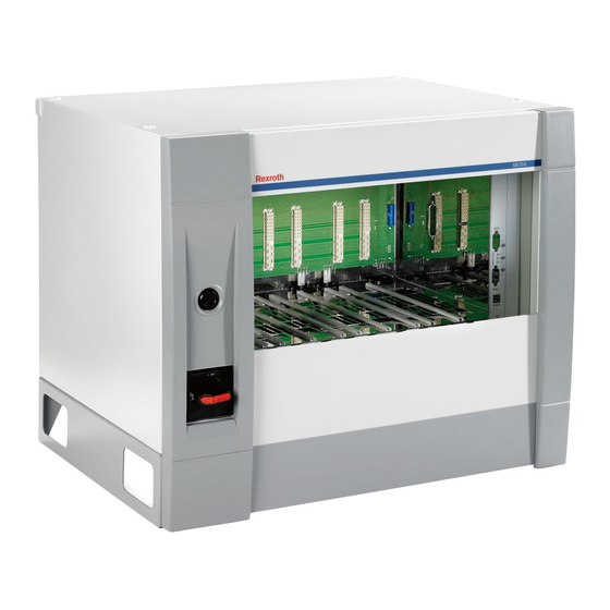
    3 609 929 B67/2008-11 | SB356 Bosch Rexroth AG 7/124 Lieferumfang Gerätebeschreibung Im Lieferumfang sind enthalten: • 1 Systembox SB356 • 1 Schlüssel • 1 Aufhängeschiene • 4 Ringschrauben M8 DIN580 • 1 Bedienungsanleitung zur Systembox SB356 Produktbeschreibung Abb. 1: Ansicht SB356 Leistungsbeschreibung Legende zu Abb.
  • Seite 8: Transport Und Lagerung

    8/124 Bosch Rexroth AG SB356 | 3 609 929 B67/2008-11 Beschriftungsfeld Transport und Lagerung Zur Kennzeichnung der Systembox (Gerätenummer im Schaltplan) ist ein Halten Sie bei Lagerung und Transport in Beschriftungsfeld angebracht, auf dem die jedem Fall die Umgebungsbedingungen ein, Gerätekennzeichnung erfolgen kann.
  • Seite 9: Systembox Sb356 Montieren

    3 609 929 B67/2008-11 | SB356 Bosch Rexroth AG 9/124 Systembox SB356 montieren ACHTUNG! VORSICHT Halten Sie die Luftwege zur Kühlung dau- erhaft frei! Gefahr von Sach- und Personenschäden! Die Hebeeinrichtungen sowie die Befestigungen der Systemboxen sind Die Montage der Systembox...
  • Seite 10 10/124 Bosch Rexroth AG SB356 | 3 609 929 B67/2008-11 10,8 25 25 Abb. 3: Montagegrafik mit Aufhängeschiene und Aushebesicherung...
  • Seite 11: Baugruppen Einsetzen

    3 609 929 B67/2008-11 | SB356 Bosch Rexroth AG 11/124 Baugruppen einsetzen Die Steckplätze 1 - 6 in der Systembox können mit einem Schraubkanal (LT35x, Setzen Sie die einzelnen Baugruppen LTU350/1, SE352(M)) bestückt werden. Die (SE352(M), KE350(G IL), LTU350/1, LT35x, KE350(G IL) muss im Steckplatz KE (rechts NK350(S)) gemäß...
  • Seite 12 12/124 Bosch Rexroth AG SB356 | 3 609 929 B67/2008-11 VORSICHT VORSICHT Gefahr von Sach- und Gefahr von Sach- und Personenschäden! Personenschäden! Allein zulässige Schutzmaßnahme Gefährliche Körperströme durch gemäß EN 50 178: Schutzerdung. unzureichende Schutzleiterverbin- Die Zuleitung zur Systembox muss...
  • Seite 13 3 609 929 B67/2008-11 | SB356 Bosch Rexroth AG 13/124 Der Netzanschluss erfolgt an den HINWEIS! Schraubklemmen am Netzschalter (Abb. 6). Die Auswahl der geeigneten Netzan- Die Kabelverschraubung (Ø 8 mm - 13 mm) schlussleitungen obliegt dem Anwender. befindet sich im Boden der Systembox (Abb.
  • Seite 14 14/124 Bosch Rexroth AG SB356 | 3 609 929 B67/2008-11 Klemmenreihen für Netzanschluss Geräteanschluss Abb. 7: Spannungswahlklemmen X1N4 (SB356) mit Anschlussgruppen G1, G2, G3 Die Trennwände der Schnittstelle X1N4 stellen eine logische Trennung der 3 Tabelle 2: Spannungswahlklemmen möglichen Pin Sig-...
  • Seite 15 3 609 929 B67/2008-11 | SB356 Bosch Rexroth AG 15/124 Leistungsschalter Netzanschlussleistungen (Nennwerte) Die erforderliche Anschlussleistung der Systembox SB356 ist abhängig von der 5 A max Anzahl und der Baugröße der daran betriebenen Schraubkanäle. Da jedoch eine Einstell- SB356 immer als vollbestückt betrachtet...
  • Seite 16 16/124 Bosch Rexroth AG SB356 | 3 609 929 B67/2008-11 Bestückung von Systemboxen Tabelle 5: Stromaufnahme Schraubkanäle Leistungsteil Schraub- Strom- Ein Schraubkanal besteht aus folgenden spindel aufnahme Komponenten: • Stationäre Schraubspindel oder LT355 Baugröße 5 45 A Handschrauber ErgoSpin mit LT354 Baugröße 4...
  • Seite 17: Inbetriebnahme

    3 609 929 B67/2008-11 | SB356 Bosch Rexroth AG 17/124 Inbetriebnahme VORSICHT Überhitzung der Systembox VORSICHT SB356 und ihrer Komponen- Gefahr von Sach- und ten! Personenschäden! Schäden an der Systembox und Die Inbetriebnahme der System- ihrer Komponenten durch Überhit- box SB356 erfordert grundle-...
  • Seite 18: Betrieb

    18/124 Bosch Rexroth AG SB356 | 3 609 929 B67/2008-11 Betrieb 4. Wählen Sie die Spannung (Werkseinstellung 400 V). 5. Stellen Sie den Leistungsschalter Q0 auf VORSICHT die entsprechende Stellung (siehe Tabelle 3) ein. Eindringender Schmutz und Flüssigkeiten führen zu 6.
  • Seite 19: Instandhaltung Und Instandsetzung

    3 609 929 B67/2008-11 | SB356 Bosch Rexroth AG 19/124 Instandhaltung und Demontage und Instandsetzung Austausch Reinigung und Pflege Notwendiges Werkzeug • Schraubendreher VORSICHT Demontage durchführen Eindringender Schmutz und Flüssigkeiten führen zu Befolgen Sie die angegebenen Störungen! Warnhinweise auf dem Aufdruck in der...
  • Seite 20: Entsorgung

    Bestimmungen Ihres Landes. Hauptschalter bzw. die Vorsi- Sie können das Gerät außerdem zur cherung aus bevor Sie an den Entsorgung an Bosch-Rexroth übersenden. Netzklemmen arbeiten. Halten Sie die Entladezeit von minde- stens 10 Sekunden ein. Prüfen Sie die Netzklemmen Erweiterung und auf Spannungsfreiheit.
  • Seite 21: Fehlersuche Und Fehlerbehebung

    3 609 929 B67/2008-11 | SB356 Bosch Rexroth AG 21/124 Fehlersuche und Fehlerbehebung Störungen und Hinweise auf Fehler werden im Schraubsystem über das BS350 angezeigt. Falls Sie den aufgetretenen Fehler nicht beheben konnten, wenden Sie sich an eine der Kontaktadressen, die Sie unter www.boschrexroth.com oder im...
  • Seite 22: Service Und Vertrieb

    22/124 Bosch Rexroth AG SB356 | 3 609 929 B67/2008-11 Service und Vertrieb Service Vertrieb Bosch Rexroth AG In Sachen System-Know-how sind wir immer Electric Drives and Controls Ihr richtiger Ansprechpartner. Schraub- und Einpress-Systeme In jedem Fall: Service von Rexroth Fornsbacher Str.
  • Seite 23 Maintenance and repair ....39 specifications, and other information set forth in it, are the exclusive property of Bosch Decommissioning ....39 Rexroth AG.
  • Seite 24: About This Document

    24/124 Bosch Rexroth AGSB356 | 3 609 929 B67/2008-11 About this document Intended use The SB356 system box is a component in These instructions contain important terms of the machine directive 98/37/EC and information on the safe and appropriate is not a ready-for-use machine. The product...
  • Seite 25: Safety Instructions In This Document

    3 609 929 B67/2008-11 | SB356 Bosch Rexroth AG 25/124 professional training, knowledge, and CAUTION experience as well as their understanding of the relevant conditions pertaining to the work CAUTION indicates a potentially to be done. Qualified personnel must hazardous situation which, if not avoided, observe the rules relevant to the subject area.
  • Seite 26 26/124 Bosch Rexroth AGSB356 | 3 609 929 B67/2008-11 Adhere to the following instructions During assembly Make sure the relevant system component is General instructions not under pressure or voltage before Only accessories and add-on units that have assembling the product or when connecting been approved for use in Rexroth tightening and disconnecting plugs.
  • Seite 27: Delivery Contents

    3 609 929 B67/2008-11 | SB356 Bosch Rexroth AG 27/124 Delivery contents Device description The delivery contents include: • 1 SB356 system box • 1 key • 1 suspension rail • 4 M8 DIN580 ring bolts • 1 SB356 system box operating...
  • Seite 28: Transport And Storage

    28/124 Bosch Rexroth AGSB356 | 3 609 929 B67/2008-11 Label area Transport and storage A label area that can be used to identify the For storing and transporting the product, unit is provided on the system box (unit always observe the ambient conditions number in circuit diagram).
  • Seite 29: Assembly

    3 609 929 B67/2008-11 | SB356 Bosch Rexroth AG 29/124 Assembly The system boxes can either be fastened to walls or racks using the mounting brackets When installing the product, always observe on the rear or placed on their bases. The the ambient conditions specified in the installation position is horizontal.
  • Seite 30 30/124 Bosch Rexroth AGSB356 | 3 609 929 B67/2008-11 10,8 25 25 Fig. 3: Assembly graphic with suspension rail and lift-out protection...
  • Seite 31 3 609 929 B67/2008-11 | SB356 Bosch Rexroth AG 31/124 Inserting the modules A maximum of one KE350(G IL) and 40 tightening channels can be operated in one Insert the individual modules (SE352(M), tightening system. KE350(G IL), LTU350/1, LT35x, NK350(S)) in the SB356 as shown in Fig.
  • Seite 32 32/124 Bosch Rexroth AGSB356 | 3 609 929 B67/2008-11 CAUTION CAUTION Risk of damage to persons Risk of damage to persons and property! and property! Solely permissible protective Dangerous shock currents due to measure in accordance with insufficient PE wire connections! EN 50 178: protective grounding.
  • Seite 33: Voltage Selection

    3 609 929 B67/2008-11 | SB356 Bosch Rexroth AG 33/124 The mains connection is via the screw NOTE! terminals on the mains switch (Fig. 6). The user is responsible for selecting The cable fitting (Ø 8 mm - 13 mm) is suitable mains connection cables.
  • Seite 34 34/124 Bosch Rexroth AGSB356 | 3 609 929 B67/2008-11 Terminal strips for mains connection Device connection Fig. 7: X1N4 voltage selection terminals (SB356) with connection groups G1, G2, G3 The X1N4 interface partitions represent a Table 2: Voltage selection terminals...
  • Seite 35: Power Switch

    3 609 929 B67/2008-11 | SB356 Bosch Rexroth AG 35/124 Power switch Mains connected loads (nominal values) The required connected load of the SB356 system box depends on the number and size 5 A max of the tightening channels to be operated. As,...
  • Seite 36 36/124 Bosch Rexroth AGSB356 | 3 609 929 B67/2008-11 Equipping the system boxes Table 5:Tightening channel power consumption Servo ampli- Tightening Power con- A tightening channel consists of the following fier spindle sumption components: • Stationary tightening spindle or ErgoSpin...
  • Seite 37: Commissioning

    3 609 929 B67/2008-11 | SB356 Bosch Rexroth AG 37/124 Commissioning CAUTION Overheating of the SB356 sys- CAUTION tem box and its components! Risk of damage to persons Damage to the system box and its and property! components from overheating...
  • Seite 38: Operation

    38/124 Bosch Rexroth AGSB356 | 3 609 929 B67/2008-11 Operation 6. Close the covers which were previously opened. 7. Connect to the mains. CAUTION 8. Insert the NK350/ NK350S network cou- Any dirt or liquids penetrating pler (if used). the device lead to 9.
  • Seite 39: Maintenance And Repair

    3 609 929 B67/2008-11 | SB356 Bosch Rexroth AG 39/124 Maintenance and Disassembly and repair replacement Cleaning and care Required tools • Screwdriver CAUTION Disassembling Any dirt or liquids penetrating the device lead to Follow the warnings imprinted on the...
  • Seite 40: Disposal

    40/124 Bosch Rexroth AGSB356 | 3 609 929 B67/2008-11 Proceed as follows to disassemble the CAUTION SB356 system box: 1. First switch off the system at the power Damage to the SB356 system switch and then at the mains or pre-fuse.
  • Seite 41: Technical Data

    3 609 929 B67/2008-11 | SB356 Bosch Rexroth AG 41/124 Technical data Table 7: Designation SB356 Order number 0 608 830 251 Input voltage 3 x 400 V ± 10%, 50 - 60 Hz (380 V to 500 V) Peak power...
  • Seite 42: Service And Sales

    42/124 Bosch Rexroth AGSB356 | 3 609 929 B67/2008-11 Service and sales Service Sales Bosch Rexroth AG We are always the right partner when it Electric Drives and Controls comes to system know-how. Schraub- und Einpress-Systeme For any problem: Service from Rexroth Fornsbacher Str.
  • Seite 43 Mise hors service ....59  Tous droits réservés par Bosch Démontage et remplacement ..59 Rexroth AG, y compris en cas de dépôt...
  • Seite 44: Au Sujet Des Présentes Instructions

    44/124 Bosch Rexroth AG SB356 | 3 609 929 B67/2008-11 Au sujet des présentes consignes d‘utilisation contenus dans les présentes instructions ne sont pas instructions respectées. • Veuillez lire les présentes instructions Les présentes instructions comprennent des attentivement et complètement avant informations importantes afin d’assurer un...
  • Seite 45: Utilisation Non Conforme

    3 609 929 B67/2008-11 | SB356 Bosch Rexroth AG 45/124 Utilisation non-conforme MOT ASSOCIÉ AU Lorsque vous utilisez le boîtier de système PICTOGRAMME SB356 autrement que décrit au chapitre Type de DANGER ! « Utilisation conforme », il s’agit là d’une utilisation non-conforme.
  • Seite 46: Consignes À Respecter

    46/124 Bosch Rexroth AG SB356 | 3 609 929 B67/2008-11 N’appliquez en aucun cas une charge REMARQUE ! mécanique inadmissible au produit. Ne vous servez jamais du produit en tant que poignée Le non-respect de ces informations est ou marche. N’y déposez pas d’objets.
  • Seite 47: Volume De Livraison

    3 609 929 B67/2008-11 | SB356 Bosch Rexroth AG 47/124 Volume de livraison Description de l’appareil Font partie de la livraison : • 1 boîtier de système SB356 • 1 clé • 1 rail de suspension • 4 anneaux de levage M8 DIN580 •...
  • Seite 48: Transport Et Stockage

    48/124 Bosch Rexroth AG SB356 | 3 609 929 B67/2008-11 Champ d’inscription Transport et stockage Pour identifier le boîtier de système (numéro Lors du transport et du stockage, veuillez en d’appareil dans le schéma de connexions), tout cas respecter les conditions ambiantes un champ d’inscription est réservé...
  • Seite 49 3 609 929 B67/2008-11 | SB356 Bosch Rexroth AG 49/124 Monter le boîtier de système SB356 ATTENTION ! ATTENTION Veillez à toujours maintenir dégagées les voies de ventilation destinées au Risque de dommages refroidissement ! personnels et matériels ! Le montage du boîtier de système...
  • Seite 50 50/124 Bosch Rexroth AG SB356 | 3 609 929 B67/2008-11 10,8 25 25 Fig. 3 : Graphique de montage avec rail de suspension et sécurité antirelevage...
  • Seite 51 3 609 929 B67/2008-11 | SB356 Bosch Rexroth AG 51/124 Insertion des modules NK350(S), le KE350(G IL) doit être inséré dans le boîtier de système contenant Insérez les différents modules (SE352(M), également le coupleur de réseaux NK350S. KE350(G IL), LTU350/1, LT35x, NK350(S)) conformément à...
  • Seite 52 52/124 Bosch Rexroth AG SB356 | 3 609 929 B67/2008-11 ATTENTION ATTENTION Risque de dommages Risque de dommages personnels et matériels ! personnels et matériels ! Seule mesure de protection Courants de chocs dangereux dus autorisée conformément à à des connexions insuffisantes EN 50 178 : protection par terre.
  • Seite 53 3 609 929 B67/2008-11 | SB356 Bosch Rexroth AG 53/124 Le branchement réseau a lieu aux bornes à Tableau 1 : Bornes de branchement réseau visser sur le commutateur réseau (Fig. 6). Description/ Tension/ Signal Le passe-câble à vis (Ø 8 mm - 13 mm) se...
  • Seite 54 54/124 Bosch Rexroth AG SB356 | 3 609 929 B67/2008-11 Barrettes à bornes pour branchement réseau Raccordement des appareils Fig. 7 : Bornes de sélection de la tension X1N4 (SB356) avec groupes de raccordement G1, G2, G3 Les cloisons de l’interface X1N4 Tableau 2 :Bornes de sélection de la tension...
  • Seite 55 3 609 929 B67/2008-11 | SB356 Bosch Rexroth AG 55/124 Puissances connectées au réseau ATTENTION ! (valeurs nominales) La puissance connectée nécessaire du Comme illustré sur le schéma de boîtier de système SB356 dépend du l’affectation des broches (tableau 2), le nombre et de la taille des canaux de vissage branchement réseau doit toujours être...
  • Seite 56 56/124 Bosch Rexroth AG SB356 | 3 609 929 B67/2008-11 Equipement des boîtiers de système Tableau 5 : Puissance absorbée des canaux de vissage Un canal de vissage est constitué des Module de Broche de Puissance composants suivants : puissance vissage absorbée...
  • Seite 57: Mise En Service

    3 609 929 B67/2008-11 | SB356 Bosch Rexroth AG 57/124 Mise en service ATTENTION Surchauffe du boîtier de ATTENTION système SB356 et de ses Risque de dommages composants ! personnels et matériels ! Endommagements du boîtier de La mise en service du boîtier de système SB356 et de ses...
  • Seite 58: Fonctionnement

    58/124 Bosch Rexroth AG SB356 | 3 609 929 B67/2008-11 Fonctionnement 4. Sélectionnez la tension (réglage d’usine 400 V). 5. Placez le disjoncteur Q0 dans la position ATTENTION correspondante (voir tableau 3). Des salissures ou des liquides 6. Refermez les caches précédemment qui pénètrent, causent des...
  • Seite 59: Entretien Et Réparations

    3 609 929 B67/2008-11 | SB356 Bosch Rexroth AG 59/124 Entretien et Mise hors service réparations Le démontage et la mise hors service du boîtier de système SB356 sont décrits au chapitre « 11 Démontage et remplacement » Nettoyage et soin à...
  • Seite 60: Elimination

    Vous pouvez en outre renvoyer l’appareil à procéder aux travaux sur les Bosch Rexroth en vue de son élimination. bornes de réseau. Respectez la durée minimale de décharge de 10 secondes.
  • Seite 61: Recherche Des Erreurs

    3 609 929 B67/2008-11 | SB356 Bosch Rexroth AG 61/124 Recherche des erreurs et élimination des erreurs Les pannes et les messages d’erreur sont affichés dans le système de vissage par l’intermédiaire du BS350. Si vous n’avez pas réussi à éliminer la perturbation qui s’est produite, veuillez vous...
  • Seite 62: Caractéristiques Techniques

    62/124 Bosch Rexroth AG SB356 | 3 609 929 B67/2008-11 Caractéristiques techniques Tableau 7 : Désignation SB356 Numéro de référence 0 608 830 251 Tension d’entrée 3 x 400 V ± 10 %, 50 - 60 Hz (380 V à 500 V)
  • Seite 63: Service Et Distribution

    3 609 929 B67/2008-11 | SB356 Bosch Rexroth AG 63/124 Service et distribution Service Distribution Bosch Rexroth AG Pour le savoir-faire en matière de système, Electric Drives and Controls nous sommes toujours l'interlocuteur qu'il Schraub- und Einpress-Systeme vous faut. Fornsbacher Str. 92...
  • Seite 64 Manutenzione e riparazione ... 80  Tutti i diritti presso Bosch Rexroth AG, Messa fuori servizio ....80 anche nel caso di deposito di diritti di Smontaggio e sostituzione .
  • Seite 65: Informazioni Sulle Presenti Istruzioni

    3 609 929 B67/2008-11 | SB356 Bosch Rexroth AG 65/124 Informazioni sulle • Conservare le istruzioni in modo che siano sempre accessibili a tutti gli utenti. presenti istruzioni • Cedere il rack di sistema SB356 a terzi sempre unitamente al manuale di istruzioni.
  • Seite 66: Qualifica Del Personale

    66/124 Bosch Rexroth AG SB356 | 3 609 929 B67/2008-11 Qualifica del personale • Simbolo di pericolo (triangolo d'emergenza): richiama l'attenzione sul Le operazioni di montaggio, messa in pericolo funzione e comando, smontaggio, • Parola di avvertimento: indica la gravità del pericolo manutenzione (incl.
  • Seite 67 3 609 929 B67/2008-11 | SB356 Bosch Rexroth AG 67/124 Indicazioni da rispettare Durante il montaggio Scollegare sempre l'alimentazione Indicazioni generali pneumatica ed elettrica della parte Nei sistemi di avvitamento Rexroth possono dell'impianto interessata prima di montare il essere utilizzati solo accessori e componenti prodotto o di collegare o scollegare i consentiti per tali sistemi.
  • Seite 68: Fornitura

    68/124 Bosch Rexroth AG SB356 | 3 609 929 B67/2008-11 Fornitura Descrizione dell’apparecchio Sono compresi nella fornitura: • 1 rack di sistema SB356 • 1 chiave • 1 guida di sospensione • 4 viti ad anello M8 DIN580 • 1 manuale di istruzioni per il rack di sistema...
  • Seite 69: Trasporto E Stoccaggio

    3 609 929 B67/2008-11 | SB356 Bosch Rexroth AG 69/124 Etichetta Trasporto e stoccaggio Per l'identificazione del rack di sistema (numero del dispositivo nello schema Durante lo stoccaggio ed il trasporto elettrico) è applicato un campo etichetta nel rispettare sempre le condizioni ambientali quale è...
  • Seite 70 70/124 Bosch Rexroth AG SB356 | 3 609 929 B67/2008-11 Montaggio del rack di sistena SB356 ATTENZIONE! CAUTELA Mantenere sempre liberi i passaggi dell'aria per il raffreddamento. Pericolo di danni a persone e cose! I dispositivi di sollevamento e i fissaggi dei...
  • Seite 71 3 609 929 B67/2008-11 | SB356 Bosch Rexroth AG 71/124 10,8 25 25 Fig. 3: Grafica per il montaggio con guida di sospensione e sicurezza antisganciamento...
  • Seite 72: Connessione Alla Rete

    72/124 Bosch Rexroth AG SB356 | 3 609 929 B67/2008-11 Inserimento dei moduli In un sistema di avvitamento possono essere gestiti al massimo una KE350(G IL) e 40 Inserire i singoli moduli (SE352(M), canali avvitatori. KE350(G IL), LTU350/1, LT35x, NK350(S)) nella SB356 come nella fig.
  • Seite 73 3 609 929 B67/2008-11 | SB356 Bosch Rexroth AG 73/124 CAUTELA CAUTELA Pericolo di danni a persone e Pericolo di danni a persone e cose! cose! Unica misura di protezione Pericolo di correnti attraverso il consentita in conformità a EN 50 corpo a causa di insufficiente 178: messa a terra di protezione.
  • Seite 74 74/124 Bosch Rexroth AG SB356 | 3 609 929 B67/2008-11 La connessione alla rete avviene tramite i Tabella 1: Morsetti di rete morsetti a vite sull'interruttore di rete (Fig. 6). Seg- Descrizione/ Tensione/ nale funzione corrente Il collegamento a vite per i cavi (Ø 8 mm -...
  • Seite 75 3 609 929 B67/2008-11 | SB356 Bosch Rexroth AG 75/124 File di morsetti per la connessione alla rete Connessione per dispositivi Fig. 7: Morsetti di scelta della tensione X1N4 (SB356) con gruppi di connessione G1, G2, G3 Tabella 2: Morsetti di scelta della tensione...
  • Seite 76 76/124 Bosch Rexroth AG SB356 | 3 609 929 B67/2008-11 Tabella 3: Comportamento di apertura dell'interrut- tore di potenza ATTENZIONE! Tensione Impostazione di cor- Devono essere collegate soltanto le rente su Q0 connessioni di un solo gruppo. 380 V 5,0 A...
  • Seite 77 3 609 929 B67/2008-11 | SB356 Bosch Rexroth AG 77/124 Tabella 4: Connessione trifase Tabella 5: Assorbimento di corrente canali avvitatori Numero di LT35x in SB356 Modulo di Avvitatore Assorbi- potenza mento di cor- rente LT353 1050 1200 1350 LT355...
  • Seite 78: Messa In Funzione

    78/124 Bosch Rexroth AG SB356 | 3 609 929 B67/2008-11 Messa in funzione CAUTELA Surriscaldamento del rack di CAUTELA sistema SB356 e dei suoi Pericolo di danni a persone e componenti! cose! Danneggiamento del rack di La messa in funzione del rack di...
  • Seite 79: Funzionamento

    3 609 929 B67/2008-11 | SB356 Bosch Rexroth AG 79/124 Funzionamento 4. Selezionare la tensione (impostazione di fabbrica 400 V). 5. Regolare l'interruttore di potenza Q0 CAUTELA sulla posizione corrispondente (ved. tabella 3). Pericolo di guasti per la penetrazione di sporco e 6.
  • Seite 80: Manutenzione E Riparazione

    80/124 Bosch Rexroth AG SB356 | 3 609 929 B67/2008-11 Manutenzione e Smontaggio e riparazione sostituzione Pulizia e cura Utensili necessari • Cacciavite CAUTELA Eseguire lo smontaggio Pericolo di guasti per la penetrazione di sporco e Seguire le avvertenze di sicurezza liquidi! dell'etichetta applicata sulla SB356.
  • Seite 81: Smaltimento

    Rispettare il tempo di È possibile inoltre spedire l'apparecchio per scarica di almeno 10 secondi. lo smaltimento alla Bosch-Rexroth. CAUTELA Pericolo di danni a persone e Ampliamento e cose!
  • Seite 82: Dati Tecnici

    82/124 Bosch Rexroth AG SB356 | 3 609 929 B67/2008-11 Dati tecnici Tabella 7: Definizione SB356 Cod. d'ord. 0 608 830 251 Tensione d’ingresso 3 x 400 V ± 10 %, 50 - 60 Hz (da 380 V a 500 V)
  • Seite 83: Assistenza E Rete Distributiva

    3 609 929 B67/2008-11 | SB356 Bosch Rexroth AG 83/124 Assistenza e rete distributiva Assistenza Rete distributiva Bosch Rexroth AG Per il know-how di sistema siamo sempre il Electric Drives and Controls vostro referente giusto. Schraub- und Einpress-Systeme In ogni caso: assistenza di Rexroth Fornsbacher Str.
  • Seite 84 Funcionamiento ..... 99 desgaste y envejecimiento.  Todos los derechos de Bosch Rexroth AG, Conservación y reparación ... . 99 también para el caso de solicitudes de...
  • Seite 85: Sobre Estas Instrucciones

    3 609 929 B67/2008-11 | SB356 Bosch Rexroth AG 85/124 Sobre estas • Si entrega la caja de sistema SB356 a terceros, entregue también las instrucciones instrucciones de manejo. Estas instrucciones contienen información Utilización correcta importante para montar, transportar, poner...
  • Seite 86: Cualificación Del Personal

    86/124 Bosch Rexroth AG SB356 | 3 609 929 B67/2008-11 Cualificación del personal • Consecuencias: describe las consecuencias en caso de no El montaje, puesta en marcha y manejo, observación desmontaje, conservación (inclusive el • Defensa: indica cómo se puede evitar el...
  • Seite 87 3 609 929 B67/2008-11 | SB356 Bosch Rexroth AG 87/124 Debe observar esto Durante el montaje Desconecte de presión y tensión el Indicaciones generales componente pertinente de la instalación En los sistemas de atornillado Rexroth sólo antes de montar el producto o conectar o deben utilizarse piezas anexas y accesorios desconectar el enchufe.
  • Seite 88: Volumen De Suministro

    88/124 Bosch Rexroth AG SB356 | 3 609 929 B67/2008-11 Volumen de suministro Descripción del aparato En el volumen de suministro se incluye: • 1 caja de sistema SB356 • 1 llave • 1 riel de suspensión • 4 tornillos con ojo M8 DIN580 •...
  • Seite 89: Transporte Y Almacenamiento

    3 609 929 B67/2008-11 | SB356 Bosch Rexroth AG 89/124 Campo de etiquetado Transporte y almacenamiento Para identificar la caja de sistema (número de aparato en el esquema de conexiones) se ha Durante el almacenamiento y el transporte previsto un campo de etiquetado en el que se cumpla siempre las condiciones ambientales puede realizar la identificación del aparato.
  • Seite 90 90/124 Bosch Rexroth AG SB356 | 3 609 929 B67/2008-11 Montar la caja de sistema SB356 ATENCIÓN PRECAUCIÓN Mantenga libres de forma permanente las vías de aire para la refrigeración. ¡Peligro de daños personales y materiales! Los dispositivos de elevación y las fijaciones de las cajas de sistema se deben diseñar de...
  • Seite 91 3 609 929 B67/2008-11 | SB356 Bosch Rexroth AG 91/124 10,8 25 25 Fig. 3: Gráfico de montaje con riel de suspensión y protección contra elevación...
  • Seite 92: Conexión A La Red

    92/124 Bosch Rexroth AG SB356 | 3 609 929 B67/2008-11 Introducir los módulos En un sistema de atornillado pueden funcionar como máximo una KE350(G IL) y Introduzca los diferentes módulos 40 canales de atornillado. (SE352(M), KE350(G IL), LTU350/1, LT35x, NK350(S)) en la SB356 según la Fig. 4.
  • Seite 93 3 609 929 B67/2008-11 | SB356 Bosch Rexroth AG 93/124 PRECAUCIÓN PRECAUCIÓN ¡Peligro de daños personales ¡Peligro de daños personales y materiales! y materiales! Única medida de protección per- Corrientes corporales peligrosas a mitida según EN 50 178: protec- consecuencia de conexiones del ción por puesta a tierra.
  • Seite 94 94/124 Bosch Rexroth AG SB356 | 3 609 929 B67/2008-11 La conexión a la red se establece en los Tabla 1: Bornes de conexión a la red bornes atornillados en el interruptor de red Descripción/ Tensión/ (Fig. 6). Señal función corriente El racor atornillado para cables (Ø...
  • Seite 95 3 609 929 B67/2008-11 | SB356 Bosch Rexroth AG 95/124 Filas de bornes para la conexión a la red Conexión al aparato Fig. 7: Bornes de selección de tensión X1N4 (SB356) con grupos de conexión G1, G2, G3 Las paredes de separación de la interface Tabla 2: Bornes de selección de tensión...
  • Seite 96 96/124 Bosch Rexroth AG SB356 | 3 609 929 B67/2008-11 Interruptor de potencia equipar con más canales de atornillado, la potencia de conexión a la red se puede diseñar según la Tabla 4. 5 A max Tabla 4: Conexión trifásica Número de LT35x en SB356...
  • Seite 97: Puesta En Marcha

    3 609 929 B67/2008-11 | SB356 Bosch Rexroth AG 97/124 Puesta en marcha Suma del consumo de corriente (unidades atornilladoras + ErgoSpin) ≤ 140 A La tabla 5 muestra un resumen del consumo PRECAUCIÓN de corriente de las unidades atornilladoras y ¡Peligro de daños personales...
  • Seite 98 98/124 Bosch Rexroth AG SB356 | 3 609 929 B67/2008-11 4. Seleccione la tensión (ajuste de fábrica PRECAUCIÓN 400 V). 5. Ajuste el interruptor de potencia Q0 en la ¡Sobrecalentamiento de la posición correspondiente (véase la caja de sistema SB356 y de Tabla 3).
  • Seite 99: Funcionamiento

    3 609 929 B67/2008-11 | SB356 Bosch Rexroth AG 99/124 Funcionamiento Conservación y reparación PRECAUCIÓN Limpieza y cuidados La suciedad y los líquidos que penetran provocan fallos. PRECAUCIÓN En caso de no observación, se La suciedad y los líquidos que pueden producir daños materiales...
  • Seite 100: Desmontaje Y Sustitución

    100/124 Bosch Rexroth AG SB356 | 3 609 929 B67/2008-11 Desmontaje y PRECAUCIÓN sustitución ¡Daños en la caja de sistema SB356 o el sistema de Herramientas necesarias atornillado por enchufar o • Destornillador extraer uniones por enchufe bajo tensión! Desmontar Desconecte primero la instalación mediante el...
  • Seite 101: Eliminación

    Además, puede enviar el aparato para su 3. Suelte los tornillos moleteados frontales eliminación a Bosch Rexroth. de todos los componentes y extráigalos. 4. Dado el caso, monte placas ciegas. Ampliaciones y reformas No puede realizar reformas en la caja de sistema SB356.
  • Seite 102: Datos Técnicos

    102/124 Bosch Rexroth AG SB356 | 3 609 929 B67/2008-11 Datos técnicos Tabla 7: Denominación SB356 N de pedido 0 608 830 251 Tensión de entrada 3 x 400 V ± 10 %, 50 - 60 Hz (380 V a 500 V) Potencia máxima...
  • Seite 103: Servicio Y Distribución

    3 609 929 B67/2008-11 | SB356 Bosch Rexroth AG 103/124 Servicio y distribución Servicio Distribución Bosch Rexroth AG En todo lo relacionado con conocimientos de Electric Drives and Controls sistemas somos siempre su contacto Schraub- und Einpress-Systeme acertado. Fornsbacher Str. 92...
  • Seite 104 Manutenção e reparos ....120  Bosch Rexroth AG, todos os direitos Retirada de funcionamento ... 120 reservados, também em caso de inscrições...
  • Seite 105: Sobre Estas Instruções

    3 609 929 B67/2008-11 | SB356 Bosch Rexroth AG 105/124 Sobre estas instruções • Em caso de venda ou empréstimo, repasse o módulo de sistema SB356 a terceiros Estas instruções contêm informações sempre junto com o manual de instrução. importantes para montar, transportar, executar, operar, manter e desmontar o Utilização correta...
  • Seite 106: Qualificação Do Pessoal

    106/124 Bosch Rexroth AG SB356 | 3 609 929 B67/2008-11 Qualificação do pessoal Esse sinal de aviso indica perigos A montagem, colocação em funcionamento e à sua saúde. Siga todas as utilização, desmontagem e manutenção instruções de segurança que se (inclusive manutenção e serviço) exigem...
  • Seite 107 3 609 929 B67/2008-11 | SB356 Bosch Rexroth AG 107/124 Tem de respeitar o seguinte Na montagem Antes de montar o aparelho, encaixar ou Indicações gerais desencaixar conectores, sempre desligue a Nos sistemas de parafusamento Rexroth só é pressão e a tensão das partes envolvidas.
  • Seite 108: Lote De Fornecimento

    108/124 Bosch Rexroth AG SB356 | 3 609 929 B67/2008-11 Lote de fornecimento Descrição do aparelho São incluídos no fornecimento: • 1 Módulo de sistema SB356 • 1 Chave • 1 Anel de suspensão • 4 Parafusos com olhal M8 DIN580 •...
  • Seite 109: Transporte E Armazenamento

    3 609 929 B67/2008-11 | SB356 Bosch Rexroth AG 109/124 Campo de rotulação Transporte e armazenamento Existe um campo de rotulação para a identificação do módulo de sistema (número Para todos os efeitos, respeite as condições de aparelho no plano de circuito elétrico), no ambientais descritas nos dados técnicos no...
  • Seite 110 110/124 Bosch Rexroth AG SB356 | 3 609 929 B67/2008-11 Montar o módulo de sistema SB356 ATENÇÃO! CUIDADO Mantenha permanentemente Risco de danos pessoais e desobstruídos os locais de passagem de materiais! ar para refrigeração! A montagem do módulo de Os guinchos e as fixações dos módulos de...
  • Seite 111 3 609 929 B67/2008-11 | SB356 Bosch Rexroth AG 111/124 10,8 25 25 Fig. 3: Gráfico de montagem com os anéis de suspensão e as presilhas de suspensão...
  • Seite 112 112/124 Bosch Rexroth AG SB356 | 3 609 929 B67/2008-11 Instalar os componentes Em um sistema de parafusamento, é possível operar no máximo um KE350(G IL) e 40 Insira os módulos (SE352(M), KE350(G IL), canais de parafusamento. LTU350/1, LT35x, NK350(S)) de acordo com a figura 4 no SB356.
  • Seite 113 3 609 929 B67/2008-11 | SB356 Bosch Rexroth AG 113/124 CUIDADO CUIDADO Risco de danos pessoais e Risco de danos pessoais e materiais! materiais! Única medida de proteção permiti- Existe o risco de correntes de cho- da de acordo com a norma EN 50 que perigosas se não houver liga-...
  • Seite 114 114/124 Bosch Rexroth AG SB356 | 3 609 929 B67/2008-11 A conexão à rede de alimentação é feita Tabela 1:Bornes de conexão à rede de alimentação pelos bornes com parafusos no interruptor Tensão/ de rede (figura 6). Sinal Descrição/Função corrente O parafusamento do cabo (Ø...
  • Seite 115 3 609 929 B67/2008-11 | SB356 Bosch Rexroth AG 115/124 Seqüências de bornes para a conexão à rede de alimentação Conexão do aparelho Fig. 7: Bornes de seleção de tensão X1N4 (SB356) com grupos de conexão G1, G2, G3 Tabela 2: Bornes de seleção de tensão Tabela 2: Bornes de seleção de tensão...
  • Seite 116 116/124 Bosch Rexroth AG SB356 | 3 609 929 B67/2008-11 Potências da conexão à rede de ATENÇÃO! alimentação (valores nominais) A potência de conexão necessária de um Como é mostrado na alocação dos pinos módulo de sistema SB356 depende da (tabela 2), a conexão à...
  • Seite 117 3 609 929 B67/2008-11 | SB356 Bosch Rexroth AG 117/124 Equipagem dos módulos de sistema Tabela 5: Absorção de corrente dos canais de parafusamento Um canal de parafusamento contém os Unidade de Parafusadeira Absorção de seguintes componentes: potência corrente • Parafusadeira estacionária ou...
  • Seite 118: Colocação Em Funcionamento

    118/124 Bosch Rexroth AG SB356 | 3 609 929 B67/2008-11 Colocação em CUIDADO funcionamento Superaquecimento do módulo de sistema SB356 e dos seus CUIDADO componentes! Risco de danos pessoais e Danos no módulo de sistema materiais! SB356 e nos seus componentes por superaquecimento.
  • Seite 119: Funcionamento

    3 609 929 B67/2008-11 | SB356 Bosch Rexroth AG 119/124 Funcionamento 4. Selecione a tensão (ajuste de fábrica 400 V). 5. Ajuste o interruptor de potência Q0 para CUIDADO a respectiva posição (ver tabela 3). A infiltração de sujeira e 6.
  • Seite 120: Manutenção E Reparos

    120/124 Bosch Rexroth AG SB356 | 3 609 929 B67/2008-11 Manutenção e reparos Desmontagem e substituição Limpeza e manutenção Ferramenta necessária CUIDADO • Chave de fenda A infiltração de sujeira e líquidos causa falhas! Efetuar a desmontagem Desta forma não é possível garan- Siga as instruções descritas na etiqueta no...
  • Seite 121: Eliminação

    3 609 929 B67/2008-11 | SB356 Bosch Rexroth AG 121/124 2. Solte os cabos de alimentação do CUIDADO módulo de sistema. 3. Soltar os parafusos recartilhados da Danos no módulo de sistema parte frontal de todos os componentes e SB356 ou no sistema de retire-os.
  • Seite 122: Dados Técnicos

    122/124 Bosch Rexroth AG SB356 | 3 609 929 B67/2008-11 Dados técnicos Tabela 7: Designação SB356 Número de referência 0 608 830 251 Tensão de entrada 3 x 400 V ± 10 %, 50 - 60 Hz (380 V a 500 V) Potência máxima...
  • Seite 123: Assistência Técnica E Vendas

    3 609 929 B67/2008-11 | SB356 Bosch Rexroth AG 123/124 Assistência técnica e vendas Assistência técnica Vendas Bosch Rexroth AG Quando se trata de know-how de sistemas, Electric Drives and Controls nós somos sempre seu parceiro de Schraub- und Einpress-Systeme confiança.
  • Seite 124 Bosch Rexroth AG Electric Drives and Controls Postfach 1161 D-71534 Murrhardt, Germany Fornsbacher Str. 92 D-71540 Murrhardt, Germany Tel.: +49 (0)71 92 22 208 Fax +49 (0)71 92 22 181 schraubtechnik@boschrexroth.de www.boschrexroth.com Ihr Ansprechpartner: Hallo...

Inhaltsverzeichnis