Castolin Eutectic Derby 182 Bedienungsanleitung
Multiprozessor schweissinverter mma/mig-mag
Inhaltsverzeichnis
Verfügbare Sprachen
Verfügbare Sprachen
Quicklinks
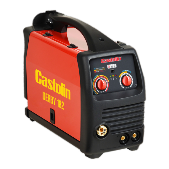
Derby 182
MULTIPROZESSOR SCHWEISSINVERTER MMA/MIG-MAG
LEGGETE LE ISTRUZIONI PRIMA DI INSTALLARE, UTILIZZARE O RIPARARE QUESTO IMPIANTO. CONSERVATE QUESTO MANUALE.
PLEASE READ THESE INSTRUCTIONS BEFORE INSTALLING, OPERATING, OR SERVICING THIS PRODUCT. DO NOT DESTROY THIS
MANUAL.
LIRE CES INSTRUCTIONS AVANT L'INSTALLATION, L'UTILISATION OU LA REPARATION DE CET APPAREIL. NE PAS JETER LE
PRÉSENT MANUEL.
LESEN SIE DIESE ANLEITUNG VOR DER INSTALLATION, DEM BETRIEB ODER DER WARTUNG DIESES PRODUKTS. NICHT ZER-
STÖREN SIE DIESES HANDBUCH. LEAN LAS INSTRUCCIONES
ANTES DE INSTALAR, UTILIZAR O REPARAR ESTOS APARATOS. CONSERVEN ESTE MANUAL.
SALDATRICE MULTIFUNZIONE MMA/MIG
MMA/MIG-MAG MULTIFUNCTION WELDER
POSTE A SOUDER MULTI PROCEDES MIG-MAG / MMA
IT MA
IT MANUALE D'ISTRUZIONE
EN IN
EN INSTRUCTION MANUAL
FR M
FR MANUEL D'UTILISATION
DE B
DE BEDIENUNGSANLEITUNG
ES M
ES MANUAL DE INSTRUCCIONES
Inhaltsverzeichnis

Verwandte Anleitungen für Castolin Eutectic Derby 182


Inhaltszusammenfassung für Castolin Eutectic Derby 182
- Seite 1 Derby 182 IT MANUALE D’ISTRUZIONE IT MA EN INSTRUCTION MANUAL EN IN FR MANUEL D’UTILISATION FR M DE BEDIENUNGSANLEITUNG DE B ES MANUAL DE INSTRUCCIONES ES M SALDATRICE MULTIFUNZIONE MMA/MIG MMA/MIG-MAG MULTIFUNCTION WELDER POSTE A SOUDER MULTI PROCEDES MIG-MAG / MMA MULTIPROZESSOR SCHWEISSINVERTER MMA/MIG-MAG LEGGETE LE ISTRUZIONI PRIMA DI INSTALLARE, UTILIZZARE O RIPARARE QUESTO IMPIANTO.
-
Seite 3: Inhaltsverzeichnis
1.0 REGLES DE SECURITE ......FR-1 1.0 NORME DI SICUREZZA ......T-1 1.1 INTRODUCTION ..............FR-1 1.1 INTRODUZIONE ..............IT-1 1.2 SECURITE DU PERSONNEL ..........FR-1 1.2 SICUREZZA PERSONALE ..........IT-1 1.3 PREVENTION CONTRE LES INCENDIES....;..FR-1 1.3 PREVENZIONE DI INCENDIO...........IT-1 1.4 ELECTROCUTION............FR-2 1.4 SHOCK ELETTRICO............IT-2 1.5 BRUITS ................FR-2 1.5 RUMORI ................IT-2 1.6 COMPATIBILITE ELECTROMAGNETIQUE ....FR-2... - Seite 4 GAS) IN AUTOMATIK.............. D-8 6.4 ALUMINIUMSCHWEISSEN ..........D-9 7.0 SCHUTZGASTABELLE ......D-9 8.0 EMPFEHLUNGEN FÜR SCHWEISSEN UND WARTUNG ..........D-9 9.0 TROUBLESHOOTING......D-10 1.0 NORMAS DE SEGURIDAD..... ES-1 1.1 INTRODUCCIÓN..............ES-1 1.2 SEGURIDAD PERSONAL..........ES-1 1.3 PREVENCION DE LOS INCENDIOS.......ES-1 1.4 ELECTROCUCIÓN ............ES-2 1.5 RUIDOS................ES-2 1.6 COMPATIBILIDAD ELECTROMAGNÉTICA ....ES-2 1.7 GASES DE PROTECCIÓN ..........ES-2 2.0 RECOMENDACIONES PARA LA...
- Seite 17 IT-12...
- Seite 43 FR-15...
-
Seite 44: Einleitung
EINLEITUNG Sicherstellen, dass dieses Handbuch von Bedien- und Wartungspersonal gleichermaßen gelesen und erfasst wird SICHERHEIT DES PERSONALS Falls die Nutzungs- und Sicherheitsvorschriften nicht genau befolgt werden, können Schweißarbeiten nicht nur für den Bediener, sondern auch für weitere Personen in unmittelbarer Nähe des Arbeitsorts gefährlich sein. Beim Schweißvorgang werden UV- und Infrarotstrahlen erzeugt, die bei nicht ausreichen- dem Schutz für die Augen schädlich sein und Hautverbrennungen verursachen können. -
Seite 45: Stromschlag
STROMSCHLAG ACHTUNG: STROMSCHLAGGEFAHR, TODESGEFAHR! • An jedem Arbeitsplatz muss eine Person mit Erste-Hilfe-Ausbildung anwesend sein. Bewusstlose Per- sonen bei Verdacht auf Stromschlag nicht berühren, so lange noch Kontakt zu den Bedienelementen besteht. Stromversorgung trennen und dann mit den Erste-Hilfe-Maßnahmen beginnen. Um Kabel vom Verletzten zu entfernen ggf. -
Seite 46: Aufstellung
2.1 AUFSTELLUNG Befolgen Sie folgende Anweisungen für eine korrekte Aufstellung Ihres Schweißgeräts: • Orte ohne Staub und Feuchtigkeit; • Temperaturen zwischen 0° und 40°C; • Orte mit Schutz gegen Öl und korrosive Dämpfe und Gase; • Orte ohne besonders intensive Schwingungen oder Stöße; •... - Seite 47 Dieses Handbuch wurde verfasst, um Hinweise zur Funktionsweise des Schweißgeräts zu liefern und enthält Informationen für einen sicheren und praktischen Gebrauch. Anleitungen über Schweißtechni- ken sind nicht Gegenstand dieses Handbuchs. Alle Empfehlungen dürfen als reine Richtangaben gesehen werden. Damit Sie sich des korrekten Zustands Ihres Schweißgeräts versichern können muss es beim Auspacken sorgfältig untersucht werden.
- Seite 48 Abb. 1 Grüne leuchtende Led zeigt an, dass der Generator unter Spannung steht; sie blinkt während des Starts und bei zu hoher Versorgungsspannung. Gelbe leuchtende Led zeigt Übertemperatur an. Rote Led leuchtet bei Überspannung oder Ausgangs- Überstrom. Wahlschalter Schweißmodus: • Schweißen mit MMA-Elektroden (Stick);...
-
Seite 49: Anschluss Zum Mma-Schweissen
Klemmen für den Polaritätswechsel des Anschlusses des Brennersteckers: • Positive Polarität für das MIG/MAG-Schweißen; • Negative Polarität für das Schweißen ohne Gas (No Gas). 5.1 ANSCHLUSS ZUM MMA-SCHWEISSEN • Den Stecker des Kabels der Massezange an die negative Buchse (8) des Generators anschließen(die für die verwendete Elektrode geforderte und auf deren Packung aufgeführte Polarität überprüfen). -
Seite 50: Drahthülle Wechseln
• Seitliche Abdeckung der Maschine schließen. An die Steckdose anschließen und einschalten. Brennerschalter drücken: Der Drahtvorschubmotor muss den Draht zur Hülle hin bewegen. Brennerschalter loslassen, sobald die Spitze hervortritt. Hinweis: Nach drei Sekunden gedrücktem Bren- nerschalter läuft der Draht schneller, um das Einlegen zu beschleunigen. -
Seite 51: Gleichstrom-Lichtbogenschweissen Ohne Gas (Mog). (Abb.7)
Die (nicht im Lieferumfang enthaltene) Gasflasche muss an der Geräterückseite mit der Kette befestigt werden. Aus Gründen der Sicherheit und Wirtschaftlichkeit sichergehen, dass der Druckregler gut ge- schlossen ist, wenn die Gasflasche nicht benutzt wird, und dass beim Anschließen und Trennen der Spule nicht geschweißt wird. •... -
Seite 52: Aluminiumschweissen
großen Änderungen der Drahtgeschwindigkeit). • Halten Sie den Brenner im kurzen Abstand zum Werkstück und drücken Sie den Brennertaster. • Draht einschleichen: min. – max. Drahtgeschwindigkeit einstellbar am Potenziometer (15 Bild 3) im Schweißgerät. • Drahtrückbrandzeit: die Drahtrückbrandzeit wird am Potenziometer (16 Bild 3) eingestellt. Sie steuert die Zeit in der der Schweißdrhat, nach Beendigung des Schweißens, zurückbrennt (Abstand zwischen Drahtende und Stromdüse). -
Seite 53: Mögliche Ursache
Die nachstehende Tabelle enthält Anweisungen zur Behebung einiger geläufiger Fehler, die auftreten können. Natürlich werden nicht alle möglichen Lösungen aufgeführt. PROBLEM MÖGLICHE URSACHE MÖGLICHE BEHEBUNG Maschine schaltet nicht ein Funktionsstörung an Versorgungska- Überprüfen, dass das Versorgungskabel bel oder Stecker. korrekt eingesteckt ist. Falsche Dimensionierung der Schmelzsicherung überprüfen und Sicherung. - Seite 54 Drahthülle gespannt oder zu lang. Hülle auf die korrekte Länge zu- schneiden. Dr ah t v e r k l e b t b e im Kontaktrohr verstopft. Kontaktrohr auswechseln. S c h m e l z e n an d er Drahtführungsspitze.
- Seite 55 D-12...
- Seite 68 SMALTIMENTO DI APPARECCHI DA ROTTAMARE DA PARTE DI PRIVATI NELL’UNIONE EUROPEA Questo simbolo che appare sul prodotto o sulla confezione indica che il prodotto non deve essere smaltito assieme agli altri rifiuti domesti- ci. Gli utenti devono provvedere allo smaltimento delle apparecchiature da rottamare portandole al luogo di raccolta indicato per il riciclag- gio delle apparecchiature elettriche ed elettroniche.