Gemü 566 Original Einbau- Und Montageanleitung
Vorschau ausblenden
Andere Handbücher für 566:
- Betriebsanleitung (120 Seiten) ,
- Beschreibung (19 Seiten) ,
- Betriebsanleitung (58 Seiten)

Verwandte Anleitungen für Gemü 566


Inhaltszusammenfassung für Gemü 566
- Seite 1 Regelventil Metall, DN 8 - 15 Control Valve Metal, DN 8 - 15 ORIGINAL EINBAU- UND MONTAGEANLEITUNG INSTALLATION, OPERATING AND MAINTENANCE INSTRUCTIONS...
-
Seite 2: Inhaltsverzeichnis
Inhaltsverzeichnis Einstellungen (elektromotorisch betätigt) Allgemeine Hinweise 12.1 Einstellung Parameter Allgemeine Sicherheitshinweise 3 12.1.1 RESET - Sollwerteingang in die Hinweise für Service- Werkseinstellung zurücksetzen für und Bedienpersonal E1 / E2 / E3 Warnhinweise 12.1.2 Elektrische Schließbegrenzung Verwendete Symbole für E1 / E2 - Stellung des Ventils Begriff... -
Seite 3: Allgemeine Hinweise
Allgemeine Hinweise Hinweise für Service- und Bedienpersonal Beschreibungen und Die Einbau- und Montageanleitung enthält Instruktionen beziehen sich auf grundlegende Sicherheitshinweise, die bei Standardausführungen. Für Inbetriebnahme, Betrieb und Instandhaltung Sonderausführungen, die in dieser zu beachten sind. Nichtbeachtung kann zur Einbau- und Montageanleitung Folge haben: nicht beschrieben sind, gelten die Gefährdung von Personen durch... -
Seite 4: Warnhinweise
Warnhinweise Verwendete Symbole Warnhinweise sind, soweit möglich, nach Gefahr durch heiße Oberfl ächen! folgendem Schema gegliedert: SIGNALWORT Gefahr durch ätzende Stoff e! Art und Quelle der Gefahr ® Mögliche Folgen bei Nichtbeachtung. Hand: Beschreibt allgemeine Maßnahmen zur Vermeidung der Hinweise und Empfehlungen. Gefahr. -
Seite 5: Vorgesehener Einsatzbereich
Vorgesehener Das 2/2-Wege-Regelventil GEMÜ 566 ist für den Einsatz in Rohrleitungen Einsatzbereich konzipiert. Es steuert ein durchfl ießendes Medium durch einen Hand-, Pneumatik- WARNUNG oder Motorantrieb. Ventil nur bestimmungsgemäß Das Ventil darf nur gemäß den einsetzen! technischen Daten eingesetzt werden ®... -
Seite 6: Technische Daten - Elektromotorisch Betätigt
Technische Daten – elektromotorisch betätigt Umgebungsbedingungen Schutzart Umgebungstemperatur -15 ... +55 °C IP 65 nach EN 60529 Stellzeit Elektrische Daten Siehe Antriebsausführung Kapitel 6.3 ca. 17 bzw. 45 s Spannungsversorgung Uv = 24 V 50/60 Hz +/- 10 % Uv = 120 V 50/60 Hz +/- 10 % Eingangswiderstand Uv = 230 V 50/60 Hz +/- 10 % 33 Ω... -
Seite 7: Bestelldaten
Bestelldaten Gehäuseform Code Ventilkörperwerkstoff Code Durchgangskörper 1.4435 (ASTM A 351 CF3M ≙ 316L), Feinguss Anschlussart Code Trennmembranwerkstoff Code Gewindemuffe DIN ISO 228 Clamp ASME BPE für Rohr ASME BPE, EPDM Baulänge EN 558, Reihe 7 Bestelldaten – manuell betätigt Steuerfunktion Code Regelcharakteristik Code... -
Seite 8: Bestelldaten - Elektromotorisch
Bestellbeispiel Nennweite Gehäuseform (Code) Anschlussart (Code) Ventilkörperwerkstoff (Code) Trennmembranwerkstoff (Code) Steuerfunktion (Code) Antriebsausführung (Code) Regelcharakteristik (Code) Kv-Wert Um ein komplettes Regelventil zu konfigurieren, muss das pneumatisch betätigte Basisventil mit einem elektropneumatischen Regler kombiniert werden. Dazu stehen die Stellungs- und Prozessregler GEMÜ 1434 μPos und 1436 cPos zur Verfügung. -
Seite 9: Herstellerangaben
Herstellerangaben Funktionsbeschreibung Das 2/2-Wege-Regelventil GEMÜ 566 verfügt über einen Körper mit integrierter Transport Regelmechanik, der durch verschiedene Ventil nur auf geeignetem Lademittel Antriebe gesteuert werden kann. Medium transportieren, nicht stürzen, vorsichtig und Antrieb sind hermetisch getrennt. handhaben. Pneumatisch betätigtes Ventil: Verpackungsmaterial entsprechend Als Steuerfunktion steht "Federkraft... -
Seite 10: Manuelle Ausführung
Montage und Anschluss Manuelle Ausführung Vor Einbau: Optische Eignung Ventilkörper- und Stellungs- anzeige Trennmembranwerkstoff entsprechend Betriebsmedium prüfen. Siehe Kapitel 5 "Technische Daten". 10.1 Montage des Ventils WARNUNG Unter Druck stehende Armaturen! ® Gefahr von schwersten Verletzungen oder Tod! Nur an druckloser Anlage arbeiten. Geräteaufbau manuelle Ausführung WARNUNG Ventilkörper... -
Seite 11: Steuerfunktion (Pneumatisch Betätigt)
Installationsort: Montage bei Gewindeanschluss: Gewindeanschluss entsprechend der VORSICHT gültigen Normen in Rohr einschrauben. Ventilkörper an Rohrleitung anschrauben, Ventil äußerlich nicht stark geeignetes Gewindedichtmittel beanspruchen. verwenden. Das Gewindedichtmittel ist Installationsort so wählen, dass Ventil nicht im Lieferumfang enthalten. nicht als Steighilfe genutzt werden Montage bei Clampanschluss: kann. -
Seite 12: Steuermedium Anschließen
10.3 Steuermedium anschließen 10.5 Regler anbauen, anschließen und einstellen Wichtig: (pneumatisch betätigt) Steuermediumleitung spannungs- Siehe Betriebsanleitung des Reglers. und knickfrei montieren! Je nach Anwendung geeignetes Anschlussstück verwenden. Elektrische Anschlüsse Gewinde des Steuermediumanschlusses: (elektromotorisch betätigt) G1/4 GEFAHR Steuerfunktion Anschlüsse Stromschlag durch Federkraft 2: Steuermedium (Öffnen) gefährliche Spannung! -
Seite 13: Vorgehensweise
11.2 Vorgehensweise Die Endlagen "AUF" und "ZU" werden über Endschalter vorgenommen. VORSICHT Die Endschalter werden von zwei an der Sichtanzeige angebrachten Schaltnocken Spannungsversorgung variiert je nach betätigt. Ausführung (siehe Typenschild). Die Mikroschalter mit Wechselkontakt Klemmen nicht überbrücken! sind intern jeweils wie folgt Bei Parallelschaltung mehrerer Antriebe verdrahtet: Der Öff... -
Seite 14: Anschlusspläne
1. Anlage spannungsfrei schalten. 2. Kabeleingang 1 aufschrauben. 3. Sechskantschrauben 2 lösen und in Abdeckung des Antriebs 3 belassen. 4. Abdeckung des Antriebs 3 demontieren. 5. Kabel durch Kabeleingang 1 einführen, ggf. inneren Dichtungsring herausnehmen. 6. Benötigte Kabel anschließen (bei eingebautem Potentiometer entfällt die Verdrahtung der Schalter S1 + S2 auf den Klemmen 5-8). - Seite 15 Funktionsmodul AE AUF/ZU Steuerung Funktionsmodul AP AUF/ZU mit 2 zusätzlichen Endlagenrückmeldungen Steuerung mit Potentiometerausgang und Hirschmannstecker N 6 R AM2 und Hirschmannstecker N 6 R AM2 (Ausführungsart: 6027) (Ausführungsart: 6027) Bezeichnung Bezeichnung L1, Motorspannung für Laufrichtung AUF L1, Motorspannung für Laufrichtung AUF L1, Motorspannung für Laufrichtung ZU L1, Motorspannung für Laufrichtung ZU N, Bezugsspannung...
-
Seite 16: Einstellungen (Elektromotorisch Betätigt)
Einstellungen GEFAHR (elektromotorisch betätigt) Stromschlag durch gefährliche Spannung! ® Verletzungen oder Tod (bei 12.1 Einstellung Parameter Betriebsspannungen größer als Schutzkleinspannungen) Bei Einsatz von integrierten Regelmodulen drohen! können Parameter anlagenspezifisch Einstellungen nur durch verändert bzw. eingestellt werden: Elektro-Fachkraft durchführen Regelmodul E1: lassen. -
Seite 17: Reset - Sollwerteingang In Die Werkseinstellung Zurücksetzen Für
12.1.1 RESET - Sollwerteingang in die 12.1.3 Elektrische Öffnungsbegrenzung für E1 / E2 - Stellung des Werkseinstellung zurücksetzen Ventils bei Sollwert 20 mA neu für E1 / E2 / E3 programmieren Betriebszustand Betriebszustand ® mittlere LED leuchtet ® mittlere LED leuchtet Oberen und unteren Taster länger als Oberen Taster länger als 1 sec. -
Seite 18: Dichtheit Des Ventils Prüfen
Dichtheit des Ventils prüfen Montage / Demontage von Ersatzteilen Wichtig: Das Ventil nur so dicht wie 14.1 Antrieb austauschen unbedingt nötig einstellen. Bei zu starker Dichtheitseinstellung wird der Antrieb unnötig stark belastet – dadurch geringere Lebensdauer. 1. Ventil in Rohrleitung einbauen. 2. -
Seite 19: Regelkegel Austauschen
14.2 Regelkegel austauschen Mit Montagewerkzeug 1. Montagewerkzeug bereithalten. Das Montagewerkzeug muss separat bestellt werden (Bestellschlüssel: 566000MWZ). 2. Antrieb demontieren (siehe Kapitel 14.1.1 "Demontage Antrieb (Antrieb von Regelmechanik lösen)". 3. Innensechskantschrauben 6 lösen. 4. Unterlegscheiben 7 entfernen. 5. Ventilkörper 1 von Regelmechanik 4 entfernen. -
Seite 20: 14.2.2 Montage Regelkegel
14.2.2 Montage Regelkegel 5. Regelmechanik 4 auf Ventilkörper 1 aufsetzen. Ohne Montagewerkzeug 6. Unterlegscheiben 7 und 1. Ventilspindel 21 und Regelkegel 3 Innensechskantschrauben 6 handfest mit montierter Trennmembrane 2 in montieren. Regelmechanik 4 schieben. 7. Innensechskantschrauben 6 über Kreuz festziehen. Dichtflächen nicht beschädigen! 2. -
Seite 21: 14.3.2 Montage Trennmembrane
Mit Montagewerkzeug 14.3.2 Montage Trennmembrane 1. Regelkegel demontieren (siehe Kapitel Ohne Montagewerkzeug 14.2.1 "Demontage Regelkegel" – Mit 1. Trennmembrane 2 mit Regelkegel 3 und Montagewerkzeug). Mutter 29 verbinden. 2. Ventilspindel 21 und Regelkegel 3 mit montierter Trennmembrane 2 in die Ausstanzung des Montagewerkzeugs einlegen (Mutter 29 befi... -
Seite 22: Inbetriebnahme
Inbetriebnahme VORSICHT Wartungs- und WARNUNG Instandhaltungstätigkeiten nur durch Aggressive Chemikalien! geschultes Fachpersonal. ® Verätzungen! Für Schäden welche durch Vor Inbetriebnahme Dichtheit unsachgemäße Handhabung oder der Medienanschlüsse Fremdeinwirkung entstehen, übernimmt GEMÜ keinerlei Haftung. prüfen! Nehmen Sie im Zweifelsfall vor Dichtheitsprüfung Inbetriebnahme Kontakt mit GEMÜ auf. nur mit geeigneter Schutzausrüstung. -
Seite 23: Rücksendung
Rücksendung Ventil reinigen. Rücksendeerklärung bei GEMÜ anfordern. Rücksendung nur mit vollständig ausgefüllter Rücksendeerklärung. Ansonsten erfolgt keine Gutschrift bzw. keine Erledigung der Reparatur sondern eine kostenpflichtige Entsorgung. Hinweis zur Rücksendung: Aufgrund gesetzlicher Bestimmungen zum Schutz der Umwelt und des Personals ist es erforderlich, dass die Rücksendeerklärung vollständig ausgefüllt und unterschrieben den Versandpapieren beiliegt. -
Seite 24: Störungsbehebung
Fehlersuche / Störungsbehebung Fehler Möglicher Grund Fehlerbehebung Steuermedium entweicht Steuermedium auf Verschmutzungen untersuchen, aus Entlüftungs- und Antrieb defekt ggf. Ventil zur Reparatur an GEMÜ senden Leckagebohrungen* Betriebsmedium entweicht Trennmembrane auf Beschädigungen prüfen, ggf. aus Entlüftungs- und Trennmembrane* defekt Trennmembrane tauschen Leckagebohrungen* Steuerdruck zu niedrig Steuerdruck gemäß... -
Seite 25: Schnittbilder Und Ersatzteile
Schnittbilder und Ersatzteile 22.1 Manuelle Ausführung Optische Stellungsanzeige Handrad Mutter Scheibe Regelmechanik Leckagebohrung Regelkegel Ventilkörper Pos. Benennung Bestellbezeichnung Trennmembrane 566 000 PAM 4/33 25 / 64... -
Seite 26: Pneumatische Ausführung
22.2 Pneumatische Ausführung GEMÜ 4232 Weggeber für den externen Anbau von Stellungs- oder Prozessreglern Antrieb Steuermediumanschluss Mutter Scheibe Regelmechanik Leckagebohrung Regelkegel Ventilkörper Pos. Benennung Bestellbezeichnung Trennmembrane 566 000 PAM 4/33 26 / 64... -
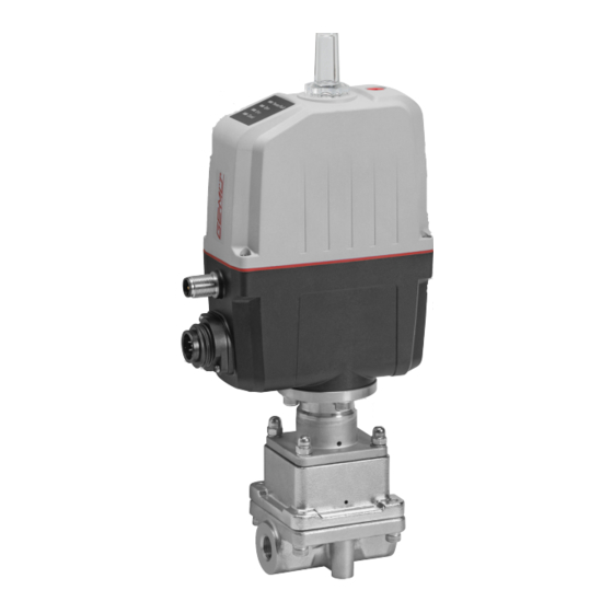
Seite 27: Elektromotorische Ausführung
22.3 Elektromotorische Ausführung Antrieb Mutter Scheibe Regelmechanik Leckagebohrung Regelkegel Ventilkörper Pos. Benennung Bestellbezeichnung Trennmembrane 566 000 PAM 4/33 27 / 64... -
Seite 28: Einbauerklärung
01.04.2014 Projektnummer: SV-Pneum-2014-04 Handelsbezeichnung: Typ 566 Es wird erklärt, dass die folgenden grundlegenden Anforderungen der Maschinenrichtlinie 2006/42/EG erfüllt sind: 1.1.3.; 1.1.5.; 1.1.7.; 1.2.1.; 1.3.; 1.3.2.; 1.3.3.; 1.3.4.; 1.3.7.; 1.3.9.; 1.5.3.; 1.5.5.; 1.5.6.; 1.5.7.; 1.5.8.; 1.5.9.; 1.6.5.; 2.1.1.; 3.2.1.; 3.2.2.; 3.3.2.; 3.4.4.; 3.6.3.1.; 4.1.2.1.; 4.1.2.3.; 4.1.2.4.; 4.1.2.5.; 4.1.2.6. a);... - Seite 29 Seriennummer: ab 29.12.2009 Projektnummer: Hubantrieb-Typ 9618-2013-11 Handelsbezeichnung: Typ 566 Es wird erklärt, dass die folgenden grundlegenden Anforderungen der Maschinenrichtlinie 2006/42/EG erfüllt sind: 1.1.7.; 1.2.1.; 1.3.4.; 1.3.7.; 1.5.1.; 1.5.16.; 1.5.2.; 1.5.5.; 1.5.6.; 1.5.7.; 1.5.8.; 1.6.3.; 3.2.1.; 4.3.3.; 5.3.; 5.4.; 6.4.3. Ferner wird erklärt, dass die speziellen technischen Unterlagen gemäß Anhang VII Teil B erstellt wurden.
-
Seite 30: Konformitätserklärung
Produkte den folgenden Richtlinien entsprechen: • Niederspannungsrichtlinie 2006/95/EG • EMV-Richtlinie 2004/108/EG Angewandte Normen: • Störaussendung EN 61000-6-4 • Störfestigkeit EN 55022 Produkte: GEMÜ 566 Joachim Brien Leiter Bereich Technik Ingelfingen-Criesbach, November 2013 30 / 64... -
Seite 31: Gemäß Anhang Vii Der Richtlinie 2014/68/Eu
Max. zulässiger Betriebsdruck PS: 6 bar Max. Nennweite: DN 15 Mediumeigenschaft nach Artikel 9: Gruppe 1 – gefährlich Benennung der Armaturen - Typenbezeichnung: Regelventil GEMÜ 566 Einstufung der Amaturen: Nach Artikel 4, Absatz 3 gute Ingenieurpraxis DN ≤ 25 Zusätzliche Angaben: Die Produkte werden entwickelt und produziert nach GEMÜ... - Seite 62 62 / 64...
- Seite 63 63 / 64...
- Seite 64 GEMÜ Gebr. Müller Apparatebau GmbH & Co. KG · Fritz-Müller-Str. 6-8 · D-74653 Ingelfi ngen-Criesbach Telefon +49(0)7940/123-0 · Telefax +49(0)7940/123-192 · info@gemue.de · www.gemu-group.com...