Herunterladen Inhalt Inhalt Diese Seite drucken
Inhaltsverzeichnis

Werbung

Verfügbare Sprachen

Verfügbare Sprachen

TMG Corporate Website
Disclaimer:
All trademarks appearing within this PDF are trademarks of their respective owners.
Form 080/01
Complimentary Reference Material
This PDF has been made available as a complimentary service for you to assist in
evaluating this model for your testing requirements.
TMG offers a wide range of test equipment solutions, from renting short to long
term, buying refurbished and purchasing new. Financing options, such as
Financial Rental, and Leasing are also available on application.
TMG will assist if you are unsure whether this model will suit your requirements.
Call TMG if you need to organise repair and/or calibrate your unit.
If you click on the "Click-to-Call" logo below, you can all us for FREE!
TMG Products Website

Werbung

Inhaltsverzeichnis
loading

Inhaltszusammenfassung für Rohde & Schwarz Hameg HM8115-2G

  • Seite 1 Complimentary Reference Material This PDF has been made available as a complimentary service for you to assist in evaluating this model for your testing requirements. TMG offers a wide range of test equipment solutions, from renting short to long term, buying refurbished and purchasing new. Financing options, such as Financial Rental, and Leasing are also available on application.
  • Seite 3 8 k W P o w e r - M e t e r H M 8 1 1 5 - 2 Handbuch / Manual / Manuel / Manual Deutsch / English / Français / Español...
  • Seite 4: Allgemeine Hinweise Zur Ce-Kennzeichnung

    A l l g e m e i n e H i n w e i s e z u r C E - K e n n z e i c h n u n g Allgemeine Hinweise zur CE-Kennzeichnung HAMEG Messgeräte erfüllen die Bestimmungen der EMV Richtlinie.
  • Seite 5: Inhaltsverzeichnis

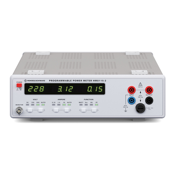
    I n h a l t s v e r z e i c h n i s English Français Español Deutsch Konformitätserklärung 8 kW Leistungsmessgerät HM8115-2 Technische Daten Wichtige Hinweise Symbole Auspacken Aufstellen des Gerätes Transport Lagerung Sicherheitshinweise Bestimmungsgemäßer Betrieb Gewährleistung und Reparataur Wartung Netzspannungsumschaltung...
  • Seite 6 H M 8 1 1 5 - 2 8 k W L e i s t u n g s - M e s s g e r ä t H M 8 1 1 5 - 2 Adapter HZ815 Großer Leistungsmessbereich 1 mW bis 8 kW Spannungsmessung 100 mV bis 500 V, Strommessung 1 mA bis 16 A Frequenzbereich DC bis 1 kHz...
  • Seite 7: Kw Leistungsmessgerät Hm8115

    T e c h n i s c h e D a t e n Verschiedenes Schutzart: Schutzklasse I (EN 61010) 8 kW Leistungs-Messgerät HM8115-2 Netzanschluss: 115/230 V ± 10 %, 50/60 Hz bei 23 °C nach einer Aufwärmzeit von 30 Minuten Leistungsaufnahme: ca.
  • Seite 8: Wichtige Hinweise

    W i c h t i g e H i n w e i s e Geräteturm kann instabil werden und auch die Wärmeent- Wichtige Hinweise wicklung kann bei gleichzeitigem Betrieb aller Geräte, zu groß werden. STOP Transport Symbole Bewahren Sie bitte den Originalkarton für einen eventuell späteren Transport auf.
  • Seite 9: Bestimmungsgemäßer Betrieb

    W i c h t i g e H i n w e i s e In folgenden Fällen ist das Gerät außer Betrieb zu setzen und Nenndaten mit Toleranzangaben gelten nach einer Anwärmzeit gegen unabsichtlichen Betrieb zu sichern: von min. 30 Minuten, im Umgebungstemperaturbereich von 15 °C bis 30 °C.
  • Seite 10: Bezeichnung Der Bedienelemente

    B e z e i c h n u n g d e r B e d i e n e l e m e n t e Bezeichnung der Bedienelemente Gerätefrontseite FUNCTION Tasten – Bereichsumschalter Messfunktion POWER – Netzschalter FUNCTION LED –...
  • Seite 11: Messgrundlagen

    M e s s g r u n d l a g e n Effektivwert Messgrundlagen Der quadratische Mittelwert x²(t) eines Signals entspricht dem Mittelwert des quadrierten Signals. ∫ — · dt Verwendete Abkürzungen und Zeichen Wirkleistung Wird aus dem quadratischen Mittelwert die Wurzel gezogen, Scheinleistung ergibt sich der Effektivwert des Signals X Blindleistung...
  • Seite 12: Leistung

    M e s s g r u n d l a g e n Wird bei einem Messgerät der maximal zulässige Crestfaktor überschritten sind die ermittelten Messwerte ungenau, da das Messgerät übersteu- û î ert wird. ω ϕ Icos ϕ STOP Die Genauigkeit des berechneten Effektivwertes ist abhängig ωt...
  • Seite 13: Leistungsfaktor

    M e s s g r u n d l a g e n Blindströme belasten das Stromversorgungsnetz. Ist zum Beispiel der Strom rechteckförmig und die Spannung Um die Blindleistung zu senken muss der Phasen- sinusförmig errechnet sich der Leistungsfaktor aus dem Ver- winkel ϕ...
  • Seite 14: Gerätekonzept Des Hm8115

    G e r ä t e k o n z e p t Gerätekonzept des HM8115-2 Einführung in die Bedienung des HM8115-2 Das Power-Meter HM8115-2 misst je einmal die Spannung Achtung - Bedienungsanleitung beachten mit einem Echteffektivwertwandler und den Strom mit einem Echteffektivwertwandler.
  • Seite 15 B e d i e n e l e m e n t e u n d A n z e i g e n Ž AMPERE Display Die neue Einstellung wird permanent gespeichert bis wieder Die Stromanzeige zeigt den Strom an, der im Messkreis fl ießt. eine Änderung erfolgt.
  • Seite 16 B e d i e n e l e m e n t e u n d A n z e i g e n • Geräteanschlüsse FUNCTION Drucktasten und Anzeige  LED für die Auswahl der MONITOR (BNC-Buchse) Messfunktion. Der Monitorausgang ermöglicht Wählbar sind: die Anzeige der Augenblickswerte...
  • Seite 17 B e d i e n e l e m e n t e u n d A n z e i g e n STOP schen 0 V und 2 V. Im arithmetischen Mittel entspre- 8 W. Entsprechend der Spezifi kation beträgt die Spannung am chend 1 V (avarage).
  • Seite 18 B e d i e n e l e m e n t e u n d A n z e i g e n R = 92 Ω ; C = 10,6 µF RC-Last: U = 50 V ; I = 161 mA ; INPUT / OUTPUT 100 V...
  • Seite 19 B e d i e n e l e m e n t e u n d A n z e i g e n = Schutzleiteranschluss PE), darf an keiner der Serielle Schnittstelle beiden INPUT-Buchsen der Spitzenwert der Span- Auf der Rückseite des POWER METER befi...
  • Seite 20 S o f t w a r e Durch die 1:1 Verbindung des Schnittstellenkabels Serielle Schnittstelle STOP wird der Datenausgang des einen Gerätes mit dem Dateneingang des anderen Gerätes verbunden. Bei PC‘s mit 25poligem COM-Port wird empfohlen, ei- Der HM8115-2 ist für den Einsatz in automatischen Testsy- nen handelsüblichen Adapter von 9polig D-Sub auf stemen bestens vorbereitet.
  • Seite 21: Befehlsliste Der Gerätesoftware

    B e f e h l s l i s t e d e r G e r ä t e s o f t w a r e Befehlsliste der Gerätesoftware Die Befehle müssen als Buchstaben- bzw. Ziffern-Zeichenkette im ASCII-Format gesendet werden. Buchstaben können in Groß- und Kleinschreibung gesendet werden.
  • Seite 22: Das Programm

    S o f t w a r e dann still. Diese Option sollte nur benutzt werden, wenn Software einzelne, manuelle Befehle über das „Command“-Feld geschickt werden! 1. Installation Sollte das Gerät korrekt erkannt werden, erscheint in der dar- unter liegenden Statusleiste die ID des Gerätes. Bei fehlerhafter Zur Installation der Software HM8115-2 starten Sie bitte die Erkennung wird „NO DEVICE DETECTET“...
  • Seite 23 S t i c h w o r t v e r z e i c h n i s PFAC Stichwortverzeichnis Phasenverschiebung 11, 12, 13, 16, 17 Phasenwinkel 13, 14, 15 POWER 10, 14 AMPERE 10, 15, 20 power factor 11, 13, 15, 16 Analogmultiplizierer Arithmetischer Mittelwert...
  • Seite 24: General Remarks Regarding The Ce Marking

    G e n e r a l i n f o r m a t i o n r e g a r d i n g t h e C E m a r k i n g General remarks regarding the CE marking HAMEG measuring instruments comply with the EMI norms.
  • Seite 25 C o n t e n t s Deutsch Français Español English Declaration of Conformity Power Meter HM8115-2 Specifi cations Important hints Symbols Unpacking Positioning Transport Storage Safety instructions Operating conditions Warranty and repair Maintenance Line voltage selector Change of fuse Designation of operating controls Basics of power measurement Arithmetic mean value...
  • Seite 26 H M 8 1 1 5 - 2 8 k W P o w e r M e t e r H M 8 1 1 5 - 2 HZ815 Power adapter Wide measurement range 1 mW to 8 kW Voltage range 100 mV to 500 V, current range 1 mA to 16 A Frequency range DC to 1 kHz Simultaneous voltage, current and power display...
  • Seite 27 S p e c i f i c a t i o n s Miscellaneous Safety Class: Safety Class I (EN 61010) 8 kW Power Meter HM8115-2 Power supply: 115/230 V ± 10 %, 50/60 Hz Valid at 23 °C after a 30 minute warm-up period Power consumption: approx.
  • Seite 28: Important Hints

    I m p o r t a n t h i n t s Transport Important hints Please keep the carton in case the instrument may require later shipment for repair. Improper packaging may void the warranty! Symbols Storage Dry indoors storage is required. After exposure to extreme STOP STOP HINT...
  • Seite 29 I m p o r t a n t h i n t s – Visible damages Do not use alcohol, solvents or paste. Under no cir- – Damage to the power cord cumstances any fl uid should be allowed to get into –...
  • Seite 30: Designation Of Operating Controls

    D e s i g n i t i o n o f o p e r a t i n g c o n t r o l s Designation of operating controls Front panel FUNCTION LED – Show function selected POWER –...
  • Seite 31: Form Factor

    B a s i c s o f P o w e r M e a s u r e m e n t Root-Mean-Square Value (RMS) Basics of Power Measurement The quadratic mean value of a signal is equal to the mean of the signal squared integrated for a full period ∫...
  • Seite 32 B a s i c s o f P o w e r M e a s u r e m e n t Please note that erroneous results will show if the is calculated from the rms voltage and the real component of crest factor of a signal is higher than that of the the current as shown in the vector diagram above.
  • Seite 33: Power Factor

    B a s i c s o f P o w e r M e a s u r e m e n t Example of power including reactive power If e.g. the current is rectangular while the voltage is sinusoi- With DC the instantanesous values of voltage and current are dal the power factor will be P/S.
  • Seite 34: Operating Controls And Displays

    C o n c e p t o f t h e H M 8 1 1 5 - 2 The instrument will automatically go into the active power Concept of the HM8115-2 measurement mode, the LED located near “FUNCTION “...
  • Seite 35 O p e r a t i n g c o n t r o l s a n d d i s p l a y s Ž Warning signal in case of overrange The AMPERE display will show the current through the Overrange will be indicated by blinking horizontal bars in the terminals.
  • Seite 36 O p e r a t i n g c o n t r o l s a n d d i s p l a y s Power factor (PF) Examples: In this mode the power factor will be measured, the LED will ...
  • Seite 37 O p e r a t i n g c o n t r o l s a n d d i s p l a y s Ω V = 50 V ; I = 161 mA ; R = 311 The frequency of the instantaneous power output 100 V is twice the mains frequency of 50 Hz hence 100 Hz.
  • Seite 38 O p e r a t i n g c o n t r o l s a n d d i s p l a y s The safety plugs may become quite hot at high currents. STOP STOP The upper two terminals (red) are internally con- nected.
  • Seite 39 O p e r a t i n g c o n t r o l s a n d d i s p l a y s Listing of software commands These commands have to be transmitted as ASCII characters, they may be lower or upper key. Each command must use oDh (Enter) at its end.
  • Seite 40: Serial Interface

    S e r i a l i n t e r f a c e Serial Interface Software The HM8115-2 is well equipped for use in automated test sy- 1. Installation stems. An optcoupler-isolated RS-232 interface is standard. For the installation of the software HM8115-2 please start the fi...
  • Seite 41: Control Panel

    G l o s s a r y Autotransfer: With this button the automatic data transfer Glossary HM8115-2 between PC and HM8115-2 can be turned on or off. If the autotransfer is off, the values in the fi elds of the ‘Control Panel’ are not being refreshed.
  • Seite 42: Déclaration De Conformité

    R e m a r q u e s g é n é r a l e s c o n c e r n a n t l e m a r q u a g e C E Avis sur le marquage CE Les instruments HAMEG répondent aux normes de la directive CEM.
  • Seite 43 S o m m a i r e Deutsch English Español Français Déclaration de conformité Remarques générales concernant le marquage CE 40 Wattmètre HM8115-2 Caractéristiques techniques Remarques importantes Symboles Déballage Mise en place de l’appareil Transport Stockage Consignes de sécurité Fonctionnement conforme aux préconisations Garantie et Réparation Maintenance...
  • Seite 44: Wattmètre Hm8115

    H M 8 1 1 5 - 2 Wa t t m è t r e 8 k W H M 8 1 1 5 - 2 Adaptateur HZ815 Grande étendue de mesure de puissance 1 mW jusqu’à 8 kW Étendue de tension 100 mV jusqu’à...
  • Seite 45: Caractéristiques Techniques

    C a r a c t é r i s t i q u e s t e c h n i q u e s Divers Alimentation : 115/230 V ± 10 %; 50/60 Hz Wattmètre 8 kW HM8115-2 Protection : Classe I, EN 61010 Caractéristiques à...
  • Seite 46: Remarques Importantes

    R e m a r q u e s i m p o r t a n t e s Transport Remarques importantes L’emballage d’origine doit être conservé pour un éventuel trans- port ultérieur. Les dommages apparaissant lors du transport et dus à...
  • Seite 47: Fonctionnement Conforme Aux Préconisations

    R e m a r q u e s i m p o r t a n t e s – Seul le personnel spécialisé ayant été formé en con- RMA par Internet: http://www.hameg.com ou par fax. Si vous séquence est habilité à ouvrir l’appareil. ne disposez pas d’emballage approprié, vous pouvez en com- –...
  • Seite 48: Désignation Des Éléments De Commande

    D é s i g n a t i o n d e s é l é m e n t s d e c o m m a n d e Désignation des éléments de commande Face avant de l’appareil DEL FUNCTION –...
  • Seite 49: Principes De Mesure

    P r i n c i p e s d e m e s u r e pliée par le facteur 2/π (0,637). Formule du calcul de la valeur Principes des mesure redressée sinusoïdale: ∫ Iû sin ωtI IuI = —...
  • Seite 50: Puissance

    P r i n c i p e s d e m e s u r e gnal par rapport à la valeur effi cace. Ce facteur est important Lorsque cela concerne la source et la charge, il se produit une pour la mesure des grandeurs pulsées.
  • Seite 51: Puissance Apparente

    P r i n c i p e s d e m e s u r e Facteur de puissance = puissance réactive = tension effi cace Le facteur de puissance PF (power factor) se calcule à partir = intensité effi cace de la formule: ϕ...
  • Seite 52: Concept De L'appareil Hm8115

    C o n c e p t d e l ’ a p p a r e i l H M 8 1 1 5 - 2 Dans ce cas également, il est possible de déterminer une Introduction à la manipulation puissance réactive.
  • Seite 53 E l é m e n t s d e c o m m a n d e e t a f f i c h a g e la tension est légèrement inférieure à la tension d’entrée. Lorsque Signal avertisseur marche/arrêt Œ...
  • Seite 54: Raccords Des Appareils

    E l é m e n t s d e c o m m a n d e e t a f f i c h a g e  pour commuter l’étendue de mesure, le système automatique L’affi chage FUNCTION indique une valeur pour le de l’étendue de mesure est désactivé.
  • Seite 55 E l é m e n t s d e c o m m a n d e e t a f f i c h a g e rés, la sortie moniteur affi che un signal de tension continue. Le Comme il s’agit d’une charge purement ohmique, il n’y a pas raccord du blindage de la fi...
  • Seite 56 E l é m e n t s d e c o m m a n d e e t a f f i c h a g e E l é m e n t s d e c o m m a n d e e t a f f i c h a g e Exemple 3: Exemple 4: Exemple 3:...
  • Seite 57 E l é m e n t s d e c o m m a n d e e t a f f i c h a g e E l é m e n t s d e c o m m a n d e e t a f f i c h a g e La résistance de mesure est protégée par un fusible accessible contraire des aiguilles d’une montre.
  • Seite 58: Liste D'instructions Du Logiciel De L'appareil

    L i s t e d ’ i n s t r u c t i o n s d u l o g i c i e l d e l ’ a p p a r e i l Liste d’instructions du logiciel de l’appareil Les instructions doivent être envoyées sous forme de chaîne de lettres ou de chiffres en format ASCII.
  • Seite 59: Interface Série

    I n t e r f a c e s é r i e Affectation des broches RS-232 sur le wattmètre et le port Interface série COM (9 broches) du PC: POWER METER PC COM Port (9 pôles) De par sa conception, l’appareil HM8115-2 est prévu pour êt- Nom / Fonction Nom / Fonction re utilisé...
  • Seite 60: Indicaciones Generales En Relación A La Marca Ce

    I n d i c a c i o n e s g e n e r a l e s e n r e l a c i ó n a l a m a r c a C E Indicaciones generales en relación a la marca CE Los instrumentos de medida HAMEG cumplen las prescripciones técnicas de la compatibilidad electromagnética (CE).
  • Seite 61 I n d i c e Deutsch English Français Español Indicaciones generales en relación a la marca CE Medidor de Potencia HM8115-2 Datos técnicos Información general Símbolos Colocación general Transporte y Almacenamiento Seguridad Condiciones de funcionamiento Garantía y reparaciones Mantenimento Cambio de tensión de red Cambio del fusible Mandos de control...
  • Seite 62 H M 8 1 1 5 - 2 M e d i d o r d e P o t e n c i a d e 8 k W H M 8 1 1 5 - 2 Adaptador HZ815 Grande medidas de potencia 1 mW hasta 8 kW Medidas de tensión 100 mV hasta 500 V, medidas de corriente 1 mA hasta 16 A...
  • Seite 63: Medidor De Potencia Hm8115

    D a t o s t é c n i c o s Varios Clase de protección: Clase de protección I (EN 61010) Medidor de Potencia de 8 kW HM8115-2 Conexión a red: 115/230 V ± 10 %, 50/60 Hz Con 23º...
  • Seite 64: Información General

    I n f o r m a c i ó n g e n e r a l Transporte y Almacenamiento Información general Aconsejamos guardar el embalaje original, por si tuviera que efectuar un transporte posteriormente. Los daños ocasionados por un transporte, en base a un embalaje insufi ciente, quedan Símbolos excluidos de la garantía.
  • Seite 65: Condiciones De Funcionamiento

    I n f o r m a c i ó n g e n e r a l Mantenimiento Cuando haya razones para suponer que ya no es posible tra- bajar con seguridad, hay que apagar el aparato y asegurar que no pueda ser puesto en marcha desintencionadamente.
  • Seite 66: Mandos De Control

    M a n d o s d e c o n t r o l FUNCTION (teclas) – Conmutador para el cambio de fun- Mandos de control ción de medida FUNCTION LED – Indicación de la función de medida Carátula frontal INPUT –...
  • Seite 67: Principios Básicos De Medida

    P r i n c i p i o s b á s i c o s d e m e d i d a π El valor de rectifi cación tiene el factor 2/ (0,637) del valor de Principios básicos de medida ω...
  • Seite 68: Factor De Cresta

    P r i n c i p i o s b á s i c o s d e m e d i d a Factor de cresta efectiva (RMS) y de la corriente efectiva. En el diagrama vec- El factor de cresta describe cuanto de más mayor es la am- torial, la corriente efectiva tiene la componente de corriente plitud (valor de pico) de una señal al valor efectivo (RMS).
  • Seite 69: Potencia Aparente

    P r i n c i p i o s b á s i c o s d e m e d i d a Con: Factor de potencia = Potencia reactiva El factor de potencia PF (power factor) se calcula según la = Tensión valor efectivo ecuación: = Corriente valor efectivo...
  • Seite 70: Funcionalidad Del Hm8115

    F u n c i o n a l i d a d d e l H M 8 1 1 5 - 2 determinar una potencia reactiva. En base a que la corriente Introducción en el manejo del HM8115-2 tiene otra forma de onda que la tensión, esta potencia reactiva se denomina también „potencia reactiva de distorsión“.
  • Seite 71 E l e m e n t o s d e m a n d o e i n d i c a c i o n e s tensión es demasiado alta para el margen de medida (Over- No soltar la tecla derecha de FUNCTION hasta que no se range), la presentación avisará...
  • Seite 72 E l e m e n t o s d e m a n d o e i n d i c a c i o n e s gama de medida demasiado pequeña, el HM8115-2 avisará con Si en vez de medir el factor de potencia PF, se mi- la intermitencia de 4 guiones „- - - -„...
  • Seite 73 E l e m e n t o s d e m a n d o e i n d i c a c i o n e s Se realiza una corrección automática de la variación por tem- La potencia media es entonces aprox. 3,24 Watt (precisión de peratura.
  • Seite 74 E l e m e n t o s d e m a n d o e i n d i c a c i o n e s ando se obtiene del circuito de medida una potencia aparente INPUT / de 8 Watt.
  • Seite 75 E l e m e n t o s d e m a n d o e i n d i c a c i o n e s La resistencia de medida queda protegida por un fusible, acce- primero, con el destornillador, una ligera presión sobre ella. sible desde el exterior y que se encuentra en el portafusibles La tapa y el fusible se pueden extraer entonces con facilidad.
  • Seite 76: Lista De Órdenes Del Programa Del Equipo

    L i s t a d e ó r d e n e s Lista de órdenes del programa del equipo Las órdenes deberán ser enviadas como cadena de letras o de números en formato ASCII. Las letras pueden ser utilizadas en mayúsculas o minúsculas.
  • Seite 77: Interfaz Rs-232

    I n t e r f a z R S - 2 3 2 Con el cable 1:1 se conecta la salida de datos de Interfaz RS-232 un aparato con la entrada del otro. Es aconsejable utilizar un adaptador si el PC está provisto de un conector de 25 polos en su interfaz RS-232.
  • Seite 78 Oscilloscopes Spectrum Analyzer Power Supplies Modular system 8000 Series Programmable Instruments 8100 Series authorized dealer w w w . h a m e g . c o m Subject to change without notice 44-8115-0240 (2) 07082008-gw HAMEG Instruments GmbH © HAMEG Instruments GmbH Industriestraße 6 A Rohde &...

Inhaltsverzeichnis