
Verwandte Anleitungen für Grundfos LSV Serie


Inhaltszusammenfassung für Grundfos LSV Serie
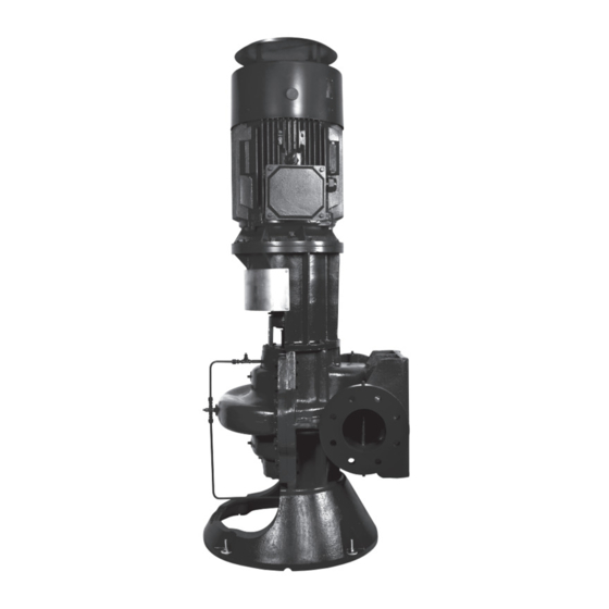
- Seite 1 GRUNDFOS INSTRUCTIONS Single-stage vertical split case pump and double-stage vertical split case pump Installation and operating instructions...
- Seite 2 English (GB) Installation and operating instructions....... . . 3 Deutsch (DE) Montage- und Betriebsanleitung .
-
Seite 3: Inhaltsverzeichnis
English (GB) Installation and operating instructions 1. General information Original installation and operating instructions These installation and operating instructions Grundfos LSV vertical split-case pumps are supplied describe LSV. either as a complete pump with motor, base frame Sections 1-4 give the information necessary to be... -
Seite 4: Notes
If any damage or losses have occurred, notify connection of pumping equipment. Grundfos' representative and the carrier's agent at once. Bolts for LSV bare-shaft pumps have US threads for which inch tools are required. - Seite 5 3.2.1 Lifting the product WARNING Crushing hazard Death or serious personal injury - Handling must be performed by qualified persons. - When unloading the pump, lift equally at four or more points on the base frame. Do not lift by the motor or by the pump. Do not lift by the flanges or by the eyebolts on the motor.
-
Seite 6: Vibration Dampers
3.2.2 Foundation We recommend that you install the pump on a concrete foundation, which is heavy enough to provide permanent and rigid support for the entire pump. The foundation must be capable of absorbing any vibration, normal strain or shock. We recommend that the weight of the concrete foundation is 3 times the weight of the complete pump unit. - Seite 7 3.2.5 Building up the foundation Shimming of base frame The foundation procedure has three steps: 1. pouring of foundation 2. shimming of base frame 3. grouting. Pouring of foundation We recommend the following procedure to ensure a good foundation: 1. Pour the foundation without interruptions to within 19-32 mm of the final level.
-
Seite 8: Electrical Connection
Grouting 3.3 Electrical connection Grouting compensates for uneven foundation, The electrical connections must be carried out by an distributes the weight of the unit, dampens vibrations authorised electrician in accordance with local and prevents shifting. Use an approved, regulations. non-shrinking grout. If you have questions or doubts about the grouting, consult an expert on grouting. -
Seite 9: Frequency Converter Operation
3.3.1 Frequency converter operation 3.4 Pipes You can connect all three-phase motors to a Protective covers are fitted to the inlet and frequency converter. outlet ports to prevent foreign bodies from However, frequency converter operation often entering the pump during transportation exposes the motor insulation system to a heavier and installation. -
Seite 10: Measuring Instruments
3.4.2 Inlet pipes 3.4.5 Auxiliary pipes Place the pump below system liquid level whenever Drains possible. This will facilitate priming, assure a steady Install the drain pipes from the pump casing and liquid flow and provide a positive suction head. stuffing boxes to a convenient disposal point. -
Seite 11: Inlet Pipe Guidelines
3.5 Inlet pipe guidelines 3.5.1 Common guidelines Avoid air pockets or turbulence in the inlet pipe Never use reducers in a horizontal inlet pipe as shown in fig. 11. Instead, use an eccentric reducer as illustrated in fig. 10. Correct Wrong Air pocket This must face downwards... -
Seite 12: Inlet Pipe If The Feed Line Comes In Different Horizontal Planes
3.5.4 Inlet pipe if the feed line comes in different horizontal planes Avoid high spots, such as loops, as they will collect air and throttle the system or lead to uneven pumping. Correct Wrong Air pocket Eccentric reducer Eccentric reducer Fig. -
Seite 13: Starting Up The Product
3.5.6 Installations with vertical inlet pipe in 4.1.2 Flushing the pipe system confined space The pump is not designed to pump liquids containing solid particles such as pipe debris and welding slag. Before starting up the pump, the pipe system must be thoroughly cleaned, flushed and filled with clean water. -
Seite 14: Direction Of Rotation
4.2.4 Direction of rotation 4.4 Startup Check the direction of rotation in the following way: 1. Start the pump. 1. Disconnect the two coupling halves between 2. Vent the pump during startup by loosening the pump and motor. vent screw until a steady flow of liquid runs out of 2. -
Seite 15: Alignment
4.5 Alignment Check shaft alignment after the pump installation is completed. The following anchoring and alignment procedures are typical and, if performed with care, should result in a smooth-running, trouble-free installation. If the pump and motor were shipped mounted on the pump base as an assembly, remove the coupling guard. -
Seite 16: Product Introduction
5. Product introduction Recheck the coupling clearance and tighten the set screws on the couplings. 5.1 Applications Tightening torques Grundfos LSV vertical split-case pumps are typically Tightening torque used in these applications: Description Dimensions [Nm] • circulation in heating- and air-conditioning systems, water condensing and boiler feed 10 ±... -
Seite 17: Identification
5.3 Identification The type designation and rating information of Grundfos vertical split-case pumps are stated on the nameplate. See fig. 23. The type designation includes model number, size and type. Permanent records for this pump are kept under its serial number and production date (fig. 23, pos. 2 and 10), and this number must therefore be stated in all correspondence and spare parts orders. - Seite 18 5.3.2 Type key The type key is an explanation of the product type designation. See fig. 23, pos. 1. Code Example 125 -100 -305X /273.1 , (W) 1 F2 D S BBQE 1 Type range LSV vertical version Nominal diameter of the inlet port (DN) Nominal diameter of the outlet port (DN) Maximum impeller diameter [mm] If suffix is used:...
- Seite 19 Code Example 125 -100 -305X /273.1 , (W) 1 F2 D S BBQE 1 Code for shaft seal or stuffing box BAQE: Rubber bellows seal, unbalanced, carbon*/SiC, EPDM BAQV: Rubber bellows seal, unbalanced, carbon*/SiC, FKM AAQE: O-ring seal, unbalanced, carbon*/SiC, EPDM AAQV: O-ring seal, unbalanced, carbon*/SiC, FKM DAQE: O-ring seal, balanced, carbon*/SiC, EPDM DAQV: O-ring seal, balanced, carbon*/SiC, FKM...
-
Seite 20: Servicing The Product
Death or serious personal injury - Pay attention to the direction of the vent If you request Grundfos to service the product, hole, and ensure that the escaping contact Grundfos with details about the liquid before water does not cause injury to persons returning the product for service. - Seite 21 6.3.2 Frequency of inspections 6.3.3 Lubrication Carry out inspections in accordance with the Pump bearings maintenance table below. Pump bearings are lubricated before delivery. Depending on operating and environmental We recommend relubricating at intervals of 2000 conditions together with a comparison of previous operating hours.
-
Seite 22: Taking The Product Out Of Operation
Texaco Polystar RB attention to the risk of injury caused by scalding hot water. Grundfos recommends KYODO YUSHI - In cold-liquid installations, pay special MULTEMP SRL, Shell Gadus S2 V2202 or SKF attention to the risk of injury caused by LGHP 2 grease for relubrication. -
Seite 23: Fault Finding The Product
8. Fault finding the product DANGER Electric shock Death or serious personal injury - Before you remove the terminal box cover and before you remove or dismantle the pump, make sure that the power supply has been switched off and that it cannot be accidentally switched Faults Causes... - Seite 24 Faults Causes A: The pump delivers no liquid. B: The pump does not deliver enough liquid. C: The pump does not create enough pressure. D: The pump loses liquid after running for a short time. E: The pump consumes too much power. The motor is overloaded.
- Seite 25 Extend the inlet pipe so that the risk of sucking air is eliminated. deeply enough. Check with Grundfos if you can use a larger impeller. If not, The impeller diameter is too small. reduce the outlet pipe friction losses. But be careful not to overload the motor.
-
Seite 26: Technical Data
Ambient temperature must not exceed +40 °C. minimum 0.5 metres head. If the ambient temperature exceeds +40 °C or the NPSH appears from the data booklet and Grundfos motor is installed more than 1000 m above sea level, Product Centre. -
Seite 27: Flange Forces And Torques
Fig. 26 Flange forces and torques Vertical pump, side branch, y-axis If not all loads reach the maximum permissible value, one of the values may exceed the normal limit. Contact Grundfos for further information. Force [N] Torque [Nm] Diameter Casting material ΣF... -
Seite 28: Disposing Of The Product
1. Use the public or private waste collection service. 2. If this is not possible, contact the nearest Grundfos company or service workshop. The crossed-out wheelie bin symbol on a product means that it must be disposed of separately from household waste. -
Seite 29: Allgemeine Informationen
Deutsch (DE) Montage- und Betriebsanleitung 1. Allgemeine Informationen Übersetzung des englischen Originaldokuments Diese Montage- und Betriebsanleitung betrifft die Die vertikalen LSV-Pumpen von Grundfos mit geteil- LSV. tem Gehäuse sind entweder als komplettes Pumpen- Die Abschnitte 1 bis 4 enthalten Informationen, die aggregat mit Motor, Grundrahmen und zugelasse- für das sichere Entpacken, Installieren und Inbetrieb-... -
Seite 30: Hinweise
3. fehlende Teile. 3.2 Montage Bauteile und Zubehör sind zum Teil einzeln verpackt oder am Pumpenaggregat befestigt. WARNUNG Informieren Sie Ihren Ansprechpartner bei Grundfos Quetschgefahr sowie die Spedition unverzüglich über jegliche Schä- Tod oder ernsthafte Personenschäden den oder fehlenden Teile. -
Seite 31: Anheben Des Produkts
3.2.1 Anheben des Produkts WARNUNG Quetschgefahr Tod oder ernsthafte Personenschäden - Die Handhabung darf nur durch ent- sprechend geschultes Personal erfol- gen. - Beim Abladen der Pumpe muss diese mindestens an vier Hebepunkten am Grundrahmen gleichmäßig angehoben werden. Heben Sie das Produkt nicht am Motor oder an der Pumpe an. -
Seite 32: Kompensatoren Kompensatoren Bieten Die Folgenden Vorteile
3.2.2 Fundamentaufstellung Es wird empfohlen, die Pumpe auf einem festen Betonfundament zu montieren. Das Fundament muss so dimensioniert sein, dass eine sichere Abstützung des gesamten Pumpenaggregats dauer- haft gewährleistet ist. Außerdem muss das Funda- ment Schwingungen und die im ordnungsgemäßen Betrieb auftretenden Kräfte und Stöße aufnehmen können. - Seite 33 3.2.5 Aufbauen des Fundaments Unterfüttern des Grundrahmens Der Vorgang zum Herstellen des Fundaments besteht aus drei Schritten: 1. Gießen des Fundaments 2. Unterfüttern des Grundrahmens 3. Einbetonieren Gießen des Fundaments Um ein tragfähiges Fundament zu erhalten, empfeh- len wir, wie folgt vorzugehen: 1.
-
Seite 34: Elektrischer Anschluss
Einzementieren 3.3 Elektrischer Anschluss Durch das Einbetonieren werden die Unebenheiten Der elektrische Anschluss darf nur von einer Elektro- des Fundaments ausgeglichen, das Gewicht des fachkraft in Übereinstimmung mit den örtlich gelten- Pumpenaggregats gleichmäßig verteilt, Schwingun- den Vorschriften vorgenommen werden. gen gedämpft und ein Verschieben des Pumpenag- gregats verhindert. -
Seite 35: Prüfung Der Rohre
Stellen Sie sicher, dass der vorhandene NPSH-Wert Betriebsbedin- (NPSHA) größer ist als der erforderliche NPSH-Wert Maßnahme gungen (NPSHR). NPSH = Net Positive Suction Head (Halte- druckhöhe). 2-, 4- und Stellen Sie sicher, dass das 3.4.1 Allgemeine Vorsichtsmaßnahmen 6-polige Moto- Motorlager an der Nichtan- ren ab Baugröße triebsseite elektrisch isoliert ist. -
Seite 36: Druckleitung
3.4.2 Zulaufleitungen 3.4.5 Zusätzliche Leitungen Sofern möglich, platzieren Sie die Pumpe immer Ablaufleitungen unterhalb der Anlagenebene. Dadurch wird das Auf- Verlegen Sie die Ablaufleitungen vom Pumpenge- füllen der Pumpe erleichtert, ein kontinuierlicher För- häuse und von der Stopfbuchse bis zu einer geeig- derstrom sichergestellt und für eine positive Saug- neten Ablaufstelle. -
Seite 37: Richtlinien Zur Zulaufleitung
3.5 Richtlinien zur Zulaufleitung 3.5.1 Allgemeine Richtlinien Vermeiden Sie Lufteinschlüsse und Verwirbelun- gen in der Zulaufleitung. Verwenden Sie niemals die in Abb. gezeigten Reduzierstücke in einer horizontalen Zulaufleitung. Verwen- den Sie stattdessen ein exzentrisches Reduzierstück wie in Abb. dargestellt. Richtig Falsch Lufteinschlüsse Muss nach unten zeigen... - Seite 38 3.5.4 Zulaufleitung mit Höhenunterschieden in der Versorgungsleitung In der Installation sollten keine erhöhten Punkte wie z. B. Schleifen vorhanden sein, da sich hier Luft ansammeln kann. Dies kann zu einem gedrosselten oder ungleichmäßigen Betrieb führen. Richtig Falsch Lufteinschlüsse Exzentrisches Reduzierstück Exzentrisches Reduzierstück Abb.
-
Seite 39: Inbetriebnahme Des Produkts
3.5.6 Installationen mit vertikal verlaufender 4.1.2 Spülen der Rohrleitungen Zulaufleitung bei beengten Platzverhältnis- Die Pumpe ist nicht dazu geeignet, Förder- medien mit Feststoffpartikeln zu fördern, wie z.B. Rohrablagerungen und Schweiß- oder Lötrückstände. Vor der Inbetrieb- nahme der Pumpe müssen die Rohrleitun- gen gründlich gereinigt, gespült und mit sauberem Wasser befüllt werden. -
Seite 40: Auffüllen
4.2.4 Drehrichtung 4.4 Inbetriebnahme Die Drehrichtung wird folgendermaßen geprüft: 1. Schalten Sie die Pumpe ein. 1. Trennen Sie die beiden Kupplungshälften, die 2. Entlüften Sie die Pumpe während des Anlaufens Pumpe und Motor miteinander verbinden. durch Lösen der Entlüftungsschraube, bis ein 2. -
Seite 41: Ausrichten
4.5 Ausrichten Überprüfen Sie nach der Installation der Pumpe die Wellenausrichtung. Im Folgenden finden Sie die üblichen Verfahren für Verankerung und Ausrichtung. Eine sorgfältige Aus- führung ist Voraussetzung für eine reibungslose Ins- tallation. Wenn Pumpe und Motor als Baugruppe auf den Pumpenfuß... -
Seite 42: Produkteinführung
5. Produkteinführung Überprüfen Sie den Kupplungsspalt erneut und zie- hen Sie die Feststellschrauben an der Kupplung fest. 5.1 Verwendungszweck Anzugsmomente In der Regel werden vertikale Grundfos LSV-Pum- Kabelquer- Anzugsmoment pen mit geteiltem Gehäuse für folgende Zwecke ein- Beschreibung schnitt [Nm] gesetzt: •... -
Seite 43: Produktidentifikation
5.3 Produktidentifikation Die Typenbezeichnung und Nenndaten der vertika- len Grundfos-Pumpen mit geteiltem Gehäuse sind auf dem Typenschild angegeben. Siehe Abb. 23. Die Typenbezeichnung umfasst die Modellnummer, die Baugröße und den Pumpentyp. Permanente Aufzeichnungen für diese Pumpe wer- den unter deren Seriennummer und dem Herstel- lungsdatum (Abb. - Seite 44 5.3.2 Typenschlüssel Der Typenschlüssel dient als Erläuterung der Typenbezeichnung. Siehe Abb.. 23, Pos. 1. Code Beispiel 125 -100 -305X /273.1 , (W) 1 F2 D S BBQE 1 Baureihe LSV in vertikaler Ausführung Nennweite des Zulaufstutzens (DN) Nennweite des Druckstutzens (DN) Maximaler Laufraddurchmesser [mm] Wenn Suffixe vorhanden sind: anderes Laufrad oder andere Konstruktion bei einstufiger...
- Seite 45 Code Beispiel 125 -100 -305X /273.1 , (W) 1 F2 D S BBQE 1 Code für Wellendichtung oder Stopfbuchse BAQE: Gummibalgdichtung, nichtentlastet, Kohle*/SiC, EPDM BAQV: Gummibalgdichtung, nichtentlastet, Kohle*/SiC, FKM AAQE: O-Ring-Dichtung, nichtentlastet, Kohle*/SiC, EPDM AAQV: O-Ring-Dichtung, nichtentlastet, Kohle*/SiC, FKM DAQE: O-Ring-Dichtung, entlastet, Kohle*/SiC, EPDM DAQV: O-Ring-Dichtung, entlastet, Kohle*/SiC, FKM SAQE: Gummibalgdichtung, entlastet, Kohle*/SiC, EPDM SAQV: Gummibalgdichtung, entlastet, Kohle*/SiC, FKM...
-
Seite 46: Servicearbeiten Am Produkt
Das Produkt gilt als kontaminiert, wenn es zum För- absichtigtes Wiedereinschalten gesi- dern einer gesundheitsschädlichen oder giftigen chert werden. Flüssigkeit eingesetzt wurde. Sollten Sie Grundfos mit der Instandsetzung des WARNUNG Produkts beauftragen, müssen Sie Grundfos vor dem Versand Informationen zum Fördermedium mit- Heiße oder kalte Oberfläche teilen. -
Seite 47: Schmierung
6.3.2 Häufigkeit der Prüfungen 6.3.3 Schmierung Halten Sie die Vorgaben im nachfolgenden War- Pumpenlager tungsplan ein. Die Pumpenlager werden vor der Auslieferung Je nach Betriebs- und Umgebungsbedingungen kön- geschmiert. nen abweichende Wartungsintervalle erforderlich Es wird empfohlen, die Lager alle 2000 Betriebsstun- sein, um einen ordnungsgemäßen Betrieb der den nachzuschmieren. -
Seite 48: Außerbetriebnahme Des Produkts
Polytac Heiße oder kalte Oberfläche Texaco Polystar RB Leichte oder mittelschwere Personenschä- Grundfos empfiehlt KYODO YUSHI MULTEMP - Stellen Sie sicher, dass das austretende SRL, Shell Gadus S2 V2202 oder SKF LGHP 2 Wasser keine Personen verletzen bzw. als Schmierfett. -
Seite 49: Störungssuche
8. Störungssuche GEFAHR Stromschlag Tod oder ernsthafte Personenschäden - Vor dem Entfernen der Klemmenkas- tenabdeckung und vor dem Montie- ren/Demontieren der Pumpe muss die Stromversorgung der Pumpe ausge- schaltet und gegen unbeabsichtigtes Wiedereinschalten gesichert werden. Störungen Ursachen A: Die Pumpe fördert keine Flüssigkeit. B: Die Pumpe fördert nicht genügend Flüssigkeit. - Seite 50 Störungen Ursachen A: Die Pumpe fördert keine Flüssigkeit. B: Die Pumpe fördert nicht genügend Flüssigkeit. C: Die Pumpe baut nicht genügend Druck auf. Die Pumpe verliert nach kurzer Betriebsdauer Flüs- sigkeit. E: Die Stromaufnahme der Pumpe ist zu hoch. Der Motor ist überlastet. G: Schwingungen treten auf.
- Seite 51 Die Zulaufleitung ist nicht tief Verlängern Sie die Zulaufleitung, damit die Pumpe keine Luft genug eingetaucht. ansaugen kann. Fragen Sie bei Grundfos nach, ob Sie ein größeres Laufrad Der Laufraddurchmesser ist zu verwenden können. Ist dies nicht möglich, reduzieren Sie die klein.
- Seite 52 Abhilfe Die Viskosität oder relative Dichte Verwenden Sie einen größeren Motor. Informationen zu emp- des Fördermediums ist größer als fohlenen Motorgrößen erhalten Sie von Grundfos. die Viskosität oder Dichte von Prüfen Sie die Viskosität und relative Dichte des Fördermedi- Wasser.
-
Seite 53: Technische Daten
[°C] Sicherheitszuschlag von mindestens 0,5 m ergibt. 1000 2250 3500 Die Haltedruckhöhe (NPSH) ist im Datenheft und im Grundfos Product Centre angegeben. Abb. 24 Motorleistung (P ) in Abhängigkeit von der Umgebungstemperatur Maximaler Eingangsdruck Die Summe aus Zulaufdruck und Pumpendruck Beispiel muss niedriger sein als der maximal zulässige Druck... -
Seite 54: Schalthäufigkeit
Sie in einem solchen Fall das Ventil auf der Druckseite. Ist ein automatisches Drosselventil ins- talliert, kann dies automatisch erfolgen. 9.1.5 Schalthäufigkeit Die empfohlene maximale Anzahl von 3 Anläufen pro Stunde gilt für komplette Pumpenaggregate, die mit einem Motor von Grundfos ausgestattet sind. -
Seite 55: Kräfte Und Anzugsmomente Bei Flanschverbindungen
Kräfte und Anzugsmomente bei Flanschverbindungen Vertikale Pumpe, Seitenstutzen, y-Achse Falls nicht alle Belastungen den maximal zulässigen Wert erreichen, darf einer dieser Werte den angege- benen Grenzwert überschreiten. Für weitergehende Informationen wenden Sie sich bitte an Grundfos. Durch- Kraft [N] Anzugsmoment [Nm] Gusswerkstoff messer ΣF... -
Seite 56: Entsorgen Des Produkts
1. Nehmen Sie öffentliche oder private Entsor- gungsbetriebe in Anspruch. 2. Sollte dies nicht möglich sein, wenden Sie sich bitte an eine Grundfos-Niederlassung oder -Ser- vicewerkstatt in Ihrer Nähe. Das Symbol mit einer durchgestrichenen Mülltonne weist darauf hin, dass das jeweilige Produkt nicht im Haushaltsmüll... - Seite 58 Argentina China Hong Kong Bombas GRUNDFOS de Argentina S.A. GRUNDFOS Pumps (Shanghai) Co. Ltd. GRUNDFOS Pumps (Hong Kong) Ltd. Ruta Panamericana km. 37.500 Centro 10F The Hub, No. 33 Suhong Road Unit 1, Ground floor Industrial Garin Minhang District Siu Wai Industrial Centre 1619 Garín Pcia.
- Seite 59 Malaysia Serbia Turkey GRUNDFOS Pumps Sdn. Bhd. Grundfos Srbija d.o.o. GRUNDFOS POMPA San. ve Tic. Ltd. 7 Jalan Peguam U1/25 Omladinskih brigada 90b Sti. Glenmarie Industrial Park 11070 Novi Beograd Gebze Organize Sanayi Bölgesi 40150 Shah Alam Phone: +381 11 2258 740...
- Seite 60 99572451 11.2020 ECM: 1257116 www.grundfos.com...